Journal of Fluid Flow, Heat and Mass Transfer (JFFHMT)
ISSN: 2368-6111

Volume 12 - Year 2025 - Pages 511-521
DOI: 10.11159/jffhmt.2025.051
Effect of Cooling Conditions on Heat Transport Performance of a Meander-Shaped Low-Fill Heat Pipe
Eiji Yazaki1, Asami Hatamoto1, Koji Fumoto1
1Aoyama Gakuin University, Department of Science and Engineering
5-10-1 Fuchinobe, Chuo-ku, Sagamihara-shi, Kanagawa, Japan 252-5258
c5624174@aoyama.jp; hatamoto@me.aoyama.ac.jp; fumoto@me.aoyama.ac.jp
Abstract - The increasing heat generation density of modern electronic devices necessitates advanced cooling technologies to maintain reliability and prevent performance degradation. A recently developed thermal device, the Meander-shaped Low-Fill Heat Pipe (MLFHP), features a meandering open-loop channel and operates effectively at extremely low filling ratios below 10 vol.%, unlike conventional pulsating heat pipes. While previous studies have demonstrated its superior temperature uniformity under natural air cooling, its performance under high heat flux conditions and different cooling environments has not been fully clarified. In this study, the heat transport characteristics of an MLFHP were experimentally investigated under three cooling conditions: natural air cooling, forced air cooling, and water cooling. The effects of filling ratio, air velocity, and cooling water flow rate on thermal performance were examined. Thermal resistance and heat transfer coefficients were evaluated using measured temperature distributions and heat input data. The results showed that the MLFHP at a filling ratio of 10 vol.% achieved significantly lower thermal resistance than at 50 vol.% under natural air cooling, with a minimum value of 0.16 K/W—approximately 80% lower than that of the conventional case. Under forced air cooling, increased air velocity enhanced tolerance to high heat flux but induced temperature oscillations in the heating section due to excessive condensation and liquid retention in the cooling section. Similarly, under water cooling, higher flow rates raised the maximum allowable heat flux by about 19%, although pronounced temperature fluctuations appeared at elevated heat inputs. These findings indicate that excessive cooling can destabilize liquid circulation within the channel despite improving heat flux tolerance. Overall, this study demonstrates that the MLFHP exhibits excellent heat transport capability at low filling ratios, making it a promising thermal management solution for compact, high-power electronic devices. The results also highlight the importance of optimizing cooling conditions to balance effective heat removal and stable operation.
Keywords: Heat pipe, Low fill, Cooling conditions.
© Copyright 2025 Authors - This is an Open Access article published under the Creative Commons Attribution License terms Creative Commons Attribution License terms. Unrestricted use, distribution, and reproduction in any medium are permitted, provided the original work is properly cited.
Date Received: 2025-04-10
Date Revised: 2025-09-26
Date Accepted: 2025-11-13
Date Published: 2025-12-30
1. Introduction
In recent years, the heat generation density of electronic components has rapidly increased as electronic devices have become increasingly compact and powerful, which far exceeds the limitations of conventional air convection cooling [1]. This high heat flux elevates chip surface temperatures, leading to reliability degradation and potential failures, thereby limiting further performance enhancement of electronic devices [2]. To handle such thermal issues, various types of heat pipes, which utilize the phase change of a working fluid filled inside to transfer heat, have long been employed [3], [4], [5], [6], [7], and [8].
However, conventional heat pipes are subject to several operational limitations such as capillary action, sonic limit, entrainment phenomenon, and boiling limit. These constraints become particularly critical when applying heat pipes to the cooling of miniaturized electronic devices. To overcome these issues, Akachi [9] proposed the pulsating heat pipe (PHP) in 1990. A PHP consists of a single narrow tube that loops between the heating section and cooling section, with a certain amount of working fluid filled inside. As the working fluid repeatedly evaporates in the heating section and condenses in the cooling section, it enables latent heat transfer through phase change and sensible heat transfer through self-excited oscillations of the fluid. Since PHPs transport liquid by self-excited oscillations of the fluid, they require no internal wick structure as in conventional heat pipes, making them promising thermal devices for contributing to the miniaturization of electronic equipment.
The thermal performance of PHPs depends on several parameters, one of which is the filling ratio of the working fluid. Rudresha et al. [10] experimentally investigated PHPs using ethylene glycol and reported that thermal resistance strongly depends on the filling ratio, with the lowest thermal resistance obtained at 55%. Rahman et al. [11] used acetone and distilled water as working fluids and showed that the optimal filling ratios were 70% and 50%, respectively, indicating that the optimum filling ratio varies depending on the fluid. Li et al. [12] showed that the optimum filling ratio for ethanol lies between 30% and 50%. They further reported that at a filling ratio of 10%, thermal resistance was lower than at other filling ratios under small heat loads, but under high heat input, insufficient liquid supply to the evaporator led to dry-out, the operational limit of PHPs. Furthermore, Czajkowski et al. [13] conducted experiments under high heat load and revealed that water demonstrated superior thermal performance compared with acetone and ethanol. With respect to cooling conditions, Ahmad et al. [14] compared natural and forced air cooling, finding that forced convection not only enabled operation under higher heat input but also improved the heat transfer limit. Shang et al. [15] demonstrated that the use of a PHP with an attached heat sink can dissipate a large heat load, and that increasing air velocity reduces the heating section temperature. Cui et al. [16] explained that the large-amplitude temperature oscillations observed under forced air cooling (air velocity 1.5 m/s) were caused by a cycle in which liquid slugs stagnated in the cooling section, driving force was accumulated to push fluid through the heating section, and subsequently, a rapid liquid movement occurred. Shi et al. [17] investigated the effect of cooling water flow rate and reported that increased flow rate lowered the cooling section temperature but resulted in increased thermal resistance. Kim et al. [18] examined PHPs under water cooling with constant heat input to the heating section and varying cooling section temperatures, and found that the length at the cooling section yielding the minimum thermal resistance depends on the cooling section temperature.
Recently, a new type of heat pipe with a meandering channel similar to PHPs but operating at extremely low filling ratios (below 10 vol.%) has been developed, namely the Meander-shaped Low-Fill Heat Pipe (MLFHP) [19]. Compared with conventional filling ratios (50 vol.%), MLFHPs demonstrated lower thermal resistance and higher effective thermal conductivity, which means improved temperature uniformity. Tsutsumiuchi et al. [20] examined the effect of installation orientation and revealed that MLFHPs maintained high thermal performance not only in the horizontal posture but also under top-heat mode. Shiokawa et al. [21] conducted experiments using alcohol-based single-component fluids (acetone and ethanol) and fluorinated inert liquids (FC-72) as working fluids for the MLFHP, which had previously only demonstrated heat transfer performance when using water as the working fluid.
These previous studies on MLFHPs have been conducted under natural air cooling conditions and have mainly focused on temperature uniformity. However, their ability to suppress temperature rise at hotspots under high heat flux has not been sufficiently investigated, as sufficient heat dissipation at the cooling section is essential to promote liquid supply to the heating section and prevent dry-out. Therefore, this study aims to clarify the heat transport characteristics of MLFHP under different cooling conditions to evaluate the thermal resistance of MLFHPs under high heat flux conditions. In this study, experiments were conducted under natural air cooling, forced air cooling, and water cooling conditions at the cooling section.
2. Experimental Setup and Methods
2. 1. Experimental Setup
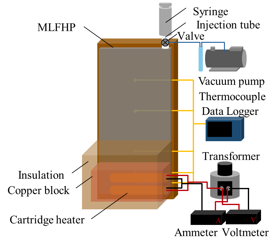
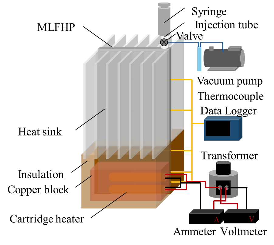
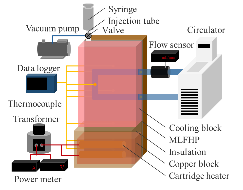
Figure 1 shows schematic diagrams of the experimental setup under three cooling conditions: natural air cooling, forced air cooling, and water cooling. The MLFHP was placed vertically, with the lower part of the channel serving as the heating section and the upper part as the cooling section. The experimental setup consisted of a heating system, a cooling system, a measurement system, a vacuum pump system with a digital vacuum gauge, and a syringe for filling the working fluid. The heating system comprised two cartridge heaters and a transformer. The heating load from the transformer was supplied to the heating section via the copper block into which the cartridge heaters were inserted. Under natural air cooling, the cooling system was open to the atmosphere. Forced air cooling was provided by a fan positioned perpendicular to the cooling surface, where heat sinks were attached. Under water cooling, cooling water from a high-low temperature circulator was circulated through the cooling block. The cooling water flow rate was controlled using a flow sensor. The entire system, except for the cooling section under air-cooling conditions, was covered with insulation material to minimize heat loss. In case of water cooling, the water block was also insulated. To reduce thermal contact resistance, thermal conductive grease was applied at the contact surface between the MLFHP and the heater block, as well as between the MLFHP and the heat sinks or cooling block. The temperatures were measured using K-type thermocouples attached to the MLFHP.
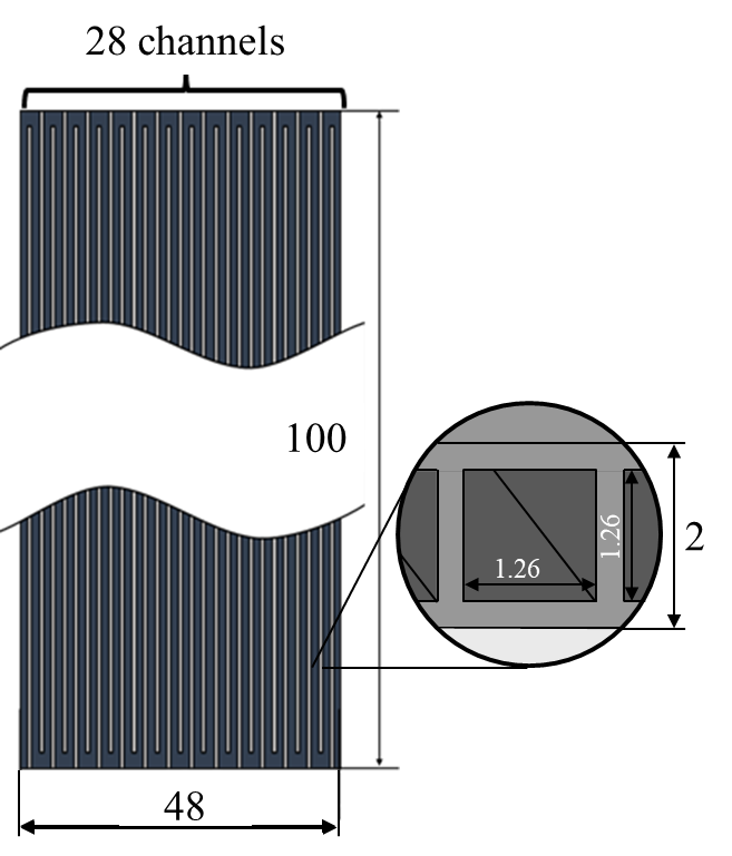
Figure 2 shows a schematic diagram of the test section and a detailed view of the channel cross-section. The test section was mainly made of aluminum and consisted of a flat tube with a total length of 100 mm, a width of 48 mm, and a thickness of 2 mm. The flow path had a meandering open-loop structure and comprised 28 square channels, each with a cross-section side length of 1.26 mm. The inner surface of the flow path was chemically treated to prevent the generation of non-condensable gases. The heating area ratio was fixed at 20 area %, while the cooling area ratio was varied. The figure illustrates the thermocouple positions for the case with a 50 area % cooling section. Thermocouples were installed along the longitudinal centreline of the MLFHP. The thermocouple positions changed according to the variation in the cooling area ratio. These measurement points were regarded as representative temperatures of the entire flow path and were used to evaluate the heat transport performance.
(a) Natural air cooling.
(b) Forced air cooling.
(c) Water cooling.
2. 2. Experimental Methods
The interior of MLFHP was evacuated to a gauge pressure below -0.100 MPa using a vacuum pump, and the vacuum condition was maintained by closing the attached valve. Subsequently, pure water was injected as the working fluid using a syringe. Since dissolved air in the working fluid could adversely affect the MLFHP operation, the working fluid was degassed beforehand using a vacuum pump [22]. The working fluid filling ratio () is defined as:

where Vfluid is the volume of working fluid at room temperature and atmospheric pressure, and VHP is internal volume of the MLFHP channels. In this experiment, the filling ratio was set to 0 vol.%, 10 vol.% and 50 vol.%.
After filling, power was supplied to the heating section from the transformer, while forced air cooling or water cooling was applied. The air velocity was defined by measuring the radial velocity distribution u(r) of a fan with radius R using a hot-wire anemometer and then calculating the mixed average air velocity U according to Eq. (2).

The applied voltage was then increased stepwise after confirming that the temperature measured by the thermocouples attached to the MLFHP had reached a steady state. Steady state was defined as the condition in which the temperature fluctuation in the heating section over a 5-min period, calculated from a moving average with a 1-min window, was within 1 K. For safety reasons, the experiment was terminated when the temperature in the heating section approached 120°C.
The experimental parameters are summarized in Table 1. In this study, cooling conditions in the cooling section were used as the primary parameter.
Table 1. Experimental parameters
(a) Under natural air cooling.
|
Cooling method |
Cooling section area |
Filling Ratio |
|
Natural air cooling |
50 area % |
50 vol.% |
|
10 vol.% |
||
|
0 vol.% |
(b) Under forced air cooling.
|
Cooling method |
Cooling section area |
Air velocity |
|
Forced air cooling |
70 area % |
0.80 m/s |
|
1.05 m/s |
||
|
1.31 m/s |
(c) Under water cooling.
|
Cooling method |
Cooling section area |
Cooling water flow rate |
|
Water cooling |
70 area % |
217 mL/min |
|
422 mL/min |
||
|
621 mL/min |
2. 3. Evaluation Methods
The heat transport performance of MLFHP was evaluated using the thermal resistance , defined in Eq. (3):


where Th and Tc are the average temperatures at the heating section (Th1 and Th2) and the cooling section (Tc1 and Tc2), respectively, calculated over a 5-min period after reaching steady state. According to Eq. (4), the net heat input Qnet supplied from the heater to the MLFHP was obtained by subtracting the heat loss to the ambient air Qloss, from the total heater power Qin.
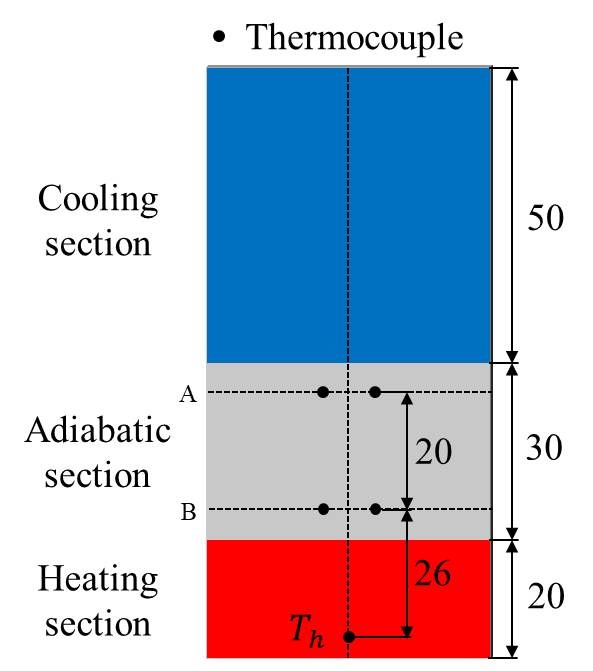
The value of Qloss was determined from a heating experiment using a solid aluminum plate, as shown in Fig. 3. Since the thermal conductivity of aluminum λAl (=222W/(m∙K)) is known, both the net heat input and the heat loss in the heating experiment were calculated using Eq. (5).

where, A is the cross-sectional area of the solid aluminum plate, TA and TB are the average temperatures at measurement points A and B, and LAB is the distance between the two measurement points.
It was assumed that Qlossdepends on the temperature difference between the heating section (Th) and the ambient air (Tatm). This correlation is shown in Fig. 4. As can be seen, Qlosswas proportional to (Th-Tatm), and thus Qloss can be expressed as:

The heat transfer coefficients for the heating and cooling sections (hh and hc, respectively) are defined as a heat transfer characteristic as follows:
where qh (=Qnet⁄Sh ) and qc (=Qc⁄Sc ) represent the heat fluxes in the heating and cooling sections, respectively, and Sh and Sc are the surface areas of each section. Qc is the heat dissipation by the cooling water, calculated from the temperature difference between the inlet and outlet of the cooling water. ∆Th (=Th-Ta) and ∆Tc (=Ta-Tc) refer to the temperature difference between the heating and insulating sections and between the insulating and cooling sections, respectively. Th,Ta,and Tc are the average temperatures of the heating, insulating, and cooling sections, respectively.
The experimental data accuracy was evaluated using the following equations:
The measurement uncertainty of the temperature difference between the heating and cooling sections was at most ±18%, while that of the heater input power was ±0.42%. Therefore, the uncertainty of the thermal resistance was estimated to be ±18%. Neglecting the measurement uncertainty of the heating and cooling surface areas, the uncertainties of the temperature difference between the heating and insulating sections and between the insulating and cooling sections were estimated to be at most ±20% and ±8%, respectively. Consequently, the uncertainties of the evaporation and condensation heat transfer coefficients were estimated to be ±20% and ±8%, respectively.
These changes were beyond the uncertainty range, indicating that the observed performance differences originated from the physical behavior of the working fluid rather than experimental error. Therefore, the conclusions regarding the optimum filling ratio and the influence of cooling conditions remain valid within the estimated uncertainty.

2. 4. Preliminary Experiment
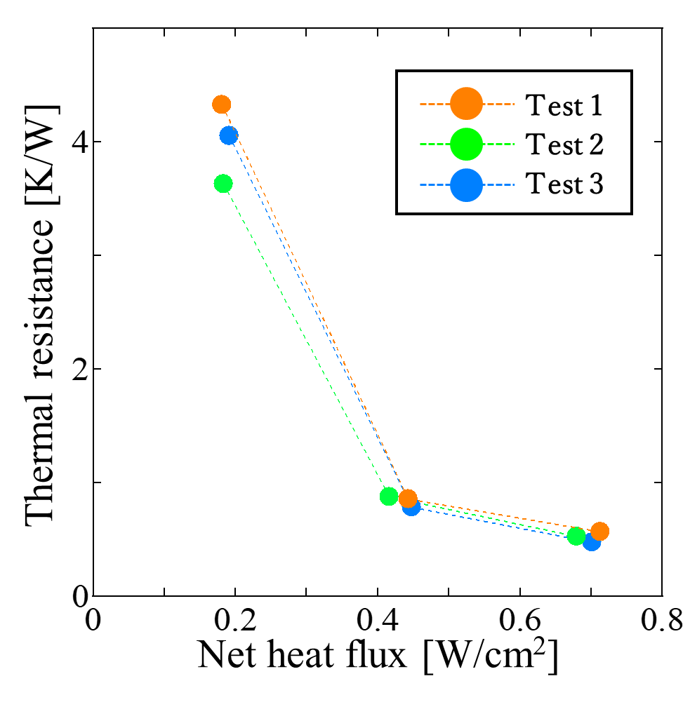
Figure 5 shows the thermal resistance obtained from three repeated experiments conducted under identical conditions to verify the reproducibility of the heat transport performance of the MLFHP. The horizontal axis represents the net heat flux, which was calculated by dividing the net heat input by the heating area. The heat exchange section ratio was set to 20 area % for the heating section and 50 area % for the cooling section. As shown in the figure, a slight variation was observed around a net heat flux of 0.2 W/cm², whereas the difference in thermal resistance among the three experiments decreased at net heat fluxes above 0.2 W/cm². This indicates that the reproducibility of the MLFHP improved with increasing net heat flux.
3. Results and Discussion
3. 1. Comparison of the MLFHP at Different Filling Ratios (50 vol.% and 10 vol.%) under Natural Air Cooling
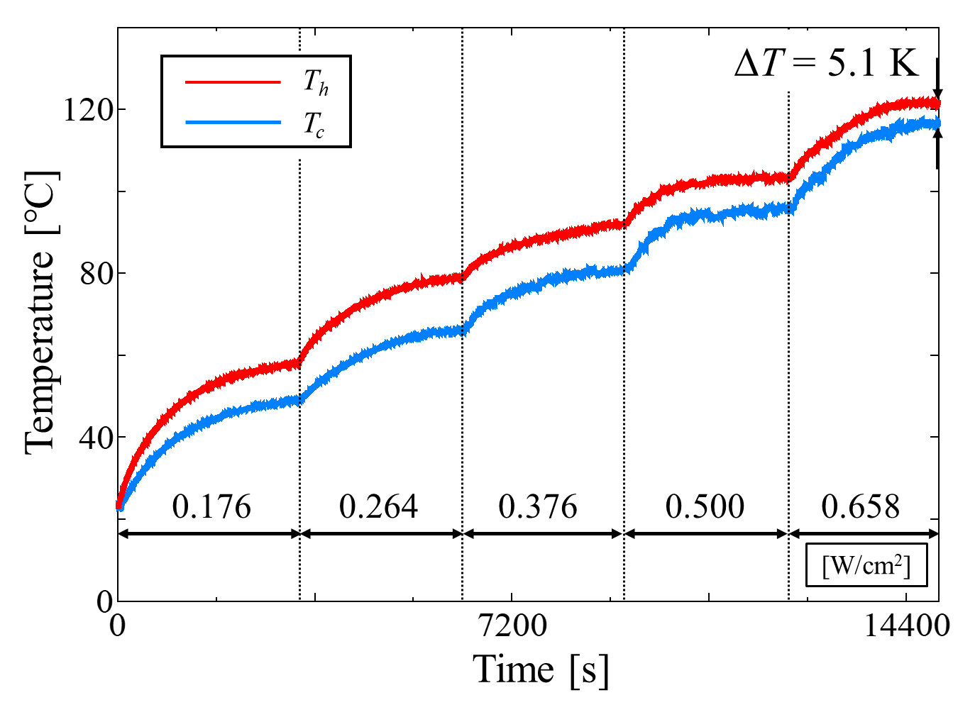
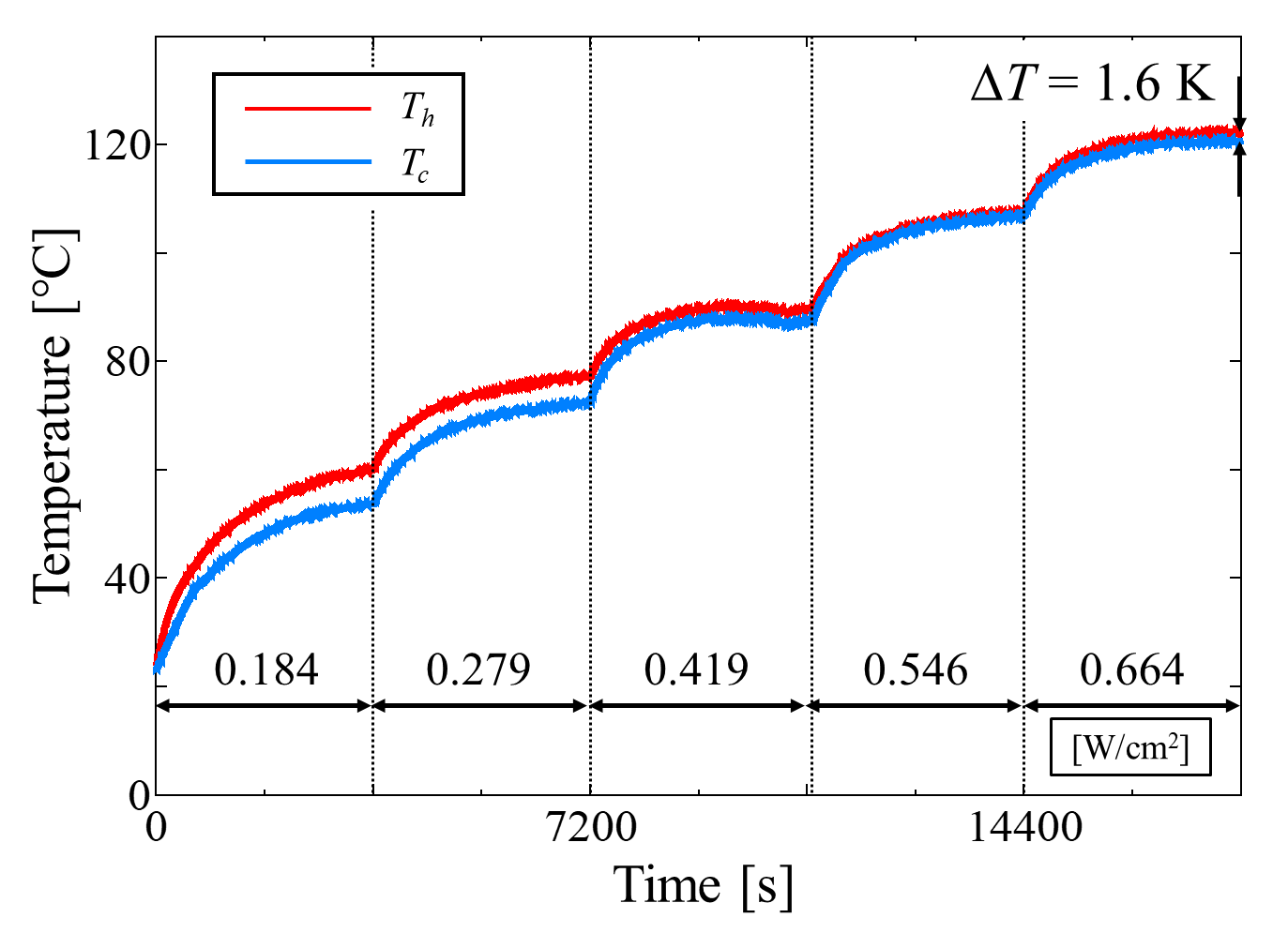
Figure 6 shows the temperature time histories of the MLFHP at filling ratios of 50 vol.% and 10 vol.%. The net heat flux and the temperature difference between the heating and cooling section are also indicated in the figures. At any heat load, the temperature difference was smaller at 10 vol.% than at 50 vol.%. In particular, the final temperature difference was 5.1 K at 50 vol.%, whereas it was reduced to 1.6 K at 10 vol.%. Focusing on the temperature behaviors, distinct temperature oscillations characteristic of PHPs were observed at 50 vol.%, while the temperature profile at 10 vol.% was smoother and more stable compared to that at 50 vol.%. A possible reason for the less pronounced oscillations at 10 vol.% is that, unlike conventional operating mechanisms, the dominant heat transfer process is latent heat transport associated with the phase change of the working fluid.
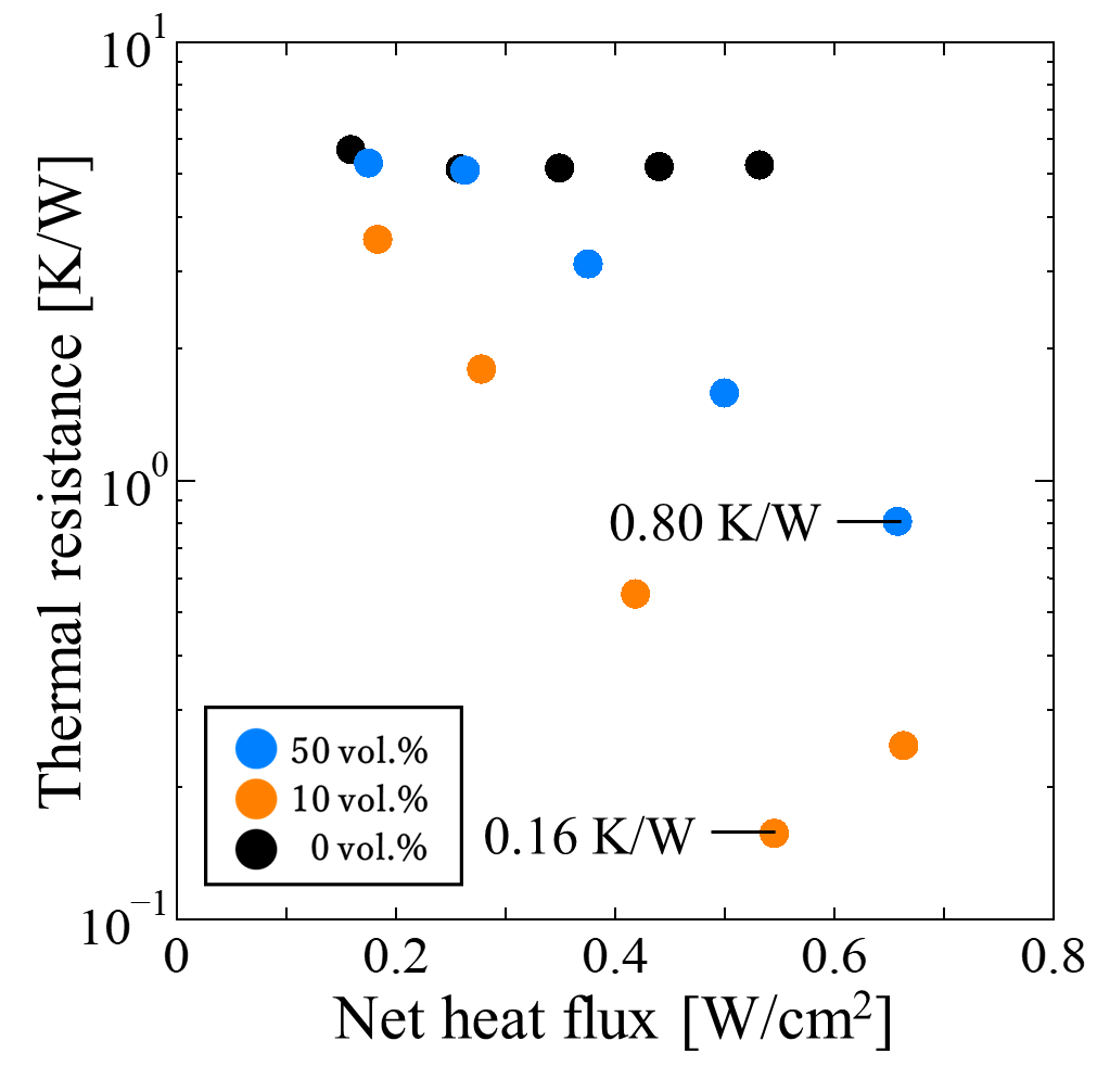
Figure 7 presents the thermal resistances at each filling ratio, with the horizontal axis representing the net heat flux. The results show that, for all heat inputs, the thermal resistance at 10 vol.% was lower than that at 50 vol.%. The minimum thermal resistance at 10 vol.% was 0.16 K/W, which represents a reduction of approximately 80% compared with the minimum value of 0.80 K/W obtained at 50 vol.%.
(a) 50 vol.%
(b) 10 vol.%
3. 2. Forced Air Cooling
In this section, the heating section temperature was used as the main evaluation parameter, as the focus is on suppressing temperature rise under high heat flux conditions.
3. 2. 1. Comparison of the MLFHP at Different Filling Ratios
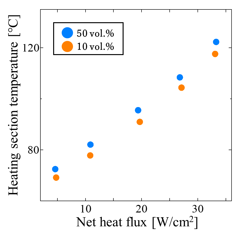
Figure 8 shows the heating section temperatures at different filling ratios under forced air cooling, where the air velocity of the fan was set to 0.80 m/s. The horizontal axis represents the net heat flux. The heat exchange section ratios were fixed at 20 area % for the heating section and 70 area % for the cooling section. As shown in the figure, at all heat inputs, the heating section temperature at 10 vol.% was lower than that at 50 vol.%, indicating better heat transport performance at the lower filling ratio. This is because, at 10 vol.%, latent heat transfer associated with phase change dominated the heat transport process, effectively suppressing the temperature rise in the heating section compared with the 50 vol.% condition.
3. 2. 2. Effect of Air Velocity
Figure 9 shows the temperature time histories obtained under forced air cooling, where the air velocity was set to 0.80 m/s and 1.31 m/s. The applied heat flux, expressed as the input power per unit heating area, is also indicated in the figure. At an air velocity of 0.80 m/s, smooth temperature profiles were observed at both the heating section and cooling sections for all heat loads. In contrast, at an air velocity of 1.31 m/s, oscillations appeared in the temperature behavior of the heating section within the heat flux range of 4.0–6.0 W/cm². Thus, increasing air velocity induced oscillatory behavior of the heating section temperature within a certain input range. This phenomenon is caused by excessive cooling, which promotes condensation of the working fluid in the cooling section and leads to liquid retention. According to previous studies by the authors, under natural air cooling, as the input power increases, the velocity of liquid slugs rising from the heating section to the cooling section increases, and the condensation location shifts upward. A similar rapid movement of liquid slugs from the heating section to the cooling section can be expected under the high heat flux conditions of this experiment. However, under forced air cooling, the surface temperature of the cooling section decreases, thereby promoting condensation of the working fluid even below the cooling section. When liquid retained in the cooling section, the liquid supply to the heating section becomes restricted. Consequently, the heating section experiences a temporary liquid deficiency, leading to superheating. As the superheating increases the thermal driving force, the stagnant liquids are set into motion and supplied to the heating section. Repetition of this process is thought to cause the observed temperature oscillations in the heating section. Moreover, it can be seen from the figure that the oscillations were suppressed as the heat load increased.
(a) 0.80 m/s
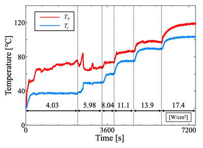
(b) 1.31 m/s
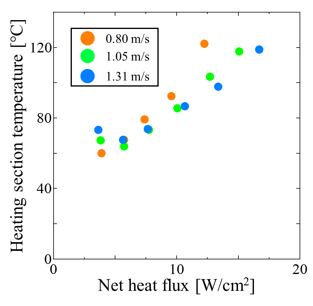
Figure 10 presents the heating section temperature for each air velocity condition, with the horizontal axis representing the net heat flux. Above 6.0 W/cm², the heating section temperature increased with heat load, but the rate of increase became more gradual at higher air velocity. At 1.31 m/s, the maximum allowable heat flux before the heating section temperature reached approximately 120°C was about 24% higher than that at 0.80 m/s, indicating improved tolerance to high heat flux conditions.
3. 3. Water Cooling
To gain a more detailed understanding of the heat transfer characteristics of the MLFHP, the heat transfer performance was evaluated separately for the heating and cooling sections.
3.3.1. Comparison of the MLFHP at Different Filling Ratios
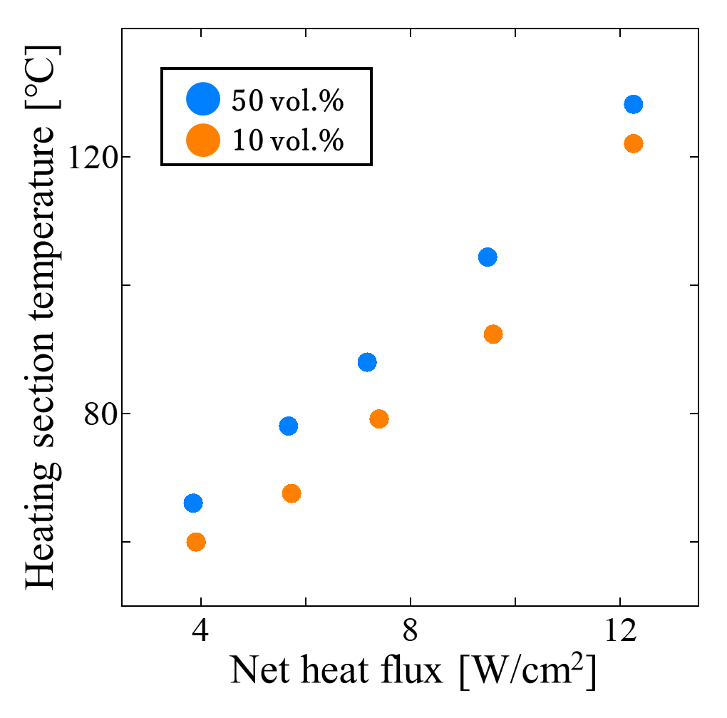
Figure 11 shows the heating section temperatures at different filling ratios under water cooling. The cooling water flow rate was 217 mL/min for the 10 vol.% case and 229 mL/min for the 50 vol.% case. The horizontal axis represents the net heat flux. Similar to the results under forced air cooling (Section 3.2.1), the heating section temperature at 10 vol.% was consistently lower than that at 50 vol.% over the entire range of heat inputs, indicating superior heat transport performance at the lower filling ratio. This tendency suggests that, at 10 vol.%, latent heat transfer associated with phase change dominated the heat transport process, effectively suppressing the temperature rise in the heating section compared with the 50 vol.% condition.
3. 3. 2. Effect of Cooling Water Flow Rate
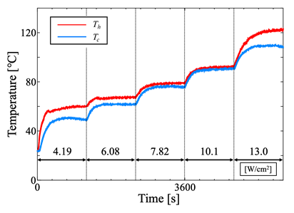
Figure 12 shows the temperature time histories obtained under water cooling, where the cooling water flow rate was set to 217 mL/min and 621 mL/min. In both cases, the inlet temperature of the cooling water was maintained constant at 40℃. The applied heat flux is also indicated in the figure. As shown in Figure 12, when the flow rate increased from 217 mL/min to 621 mL/min, the maximum allowable heat flux before the heating section temperature reached approximately 120°C increased by about 19%. On the other hand, at 621 mL/min, pronounced fluctuations were observed in the temperature profiles of both the heating and cooling sections. The largest temperature oscillations occurred under a heat flux of about 11 W/cm².
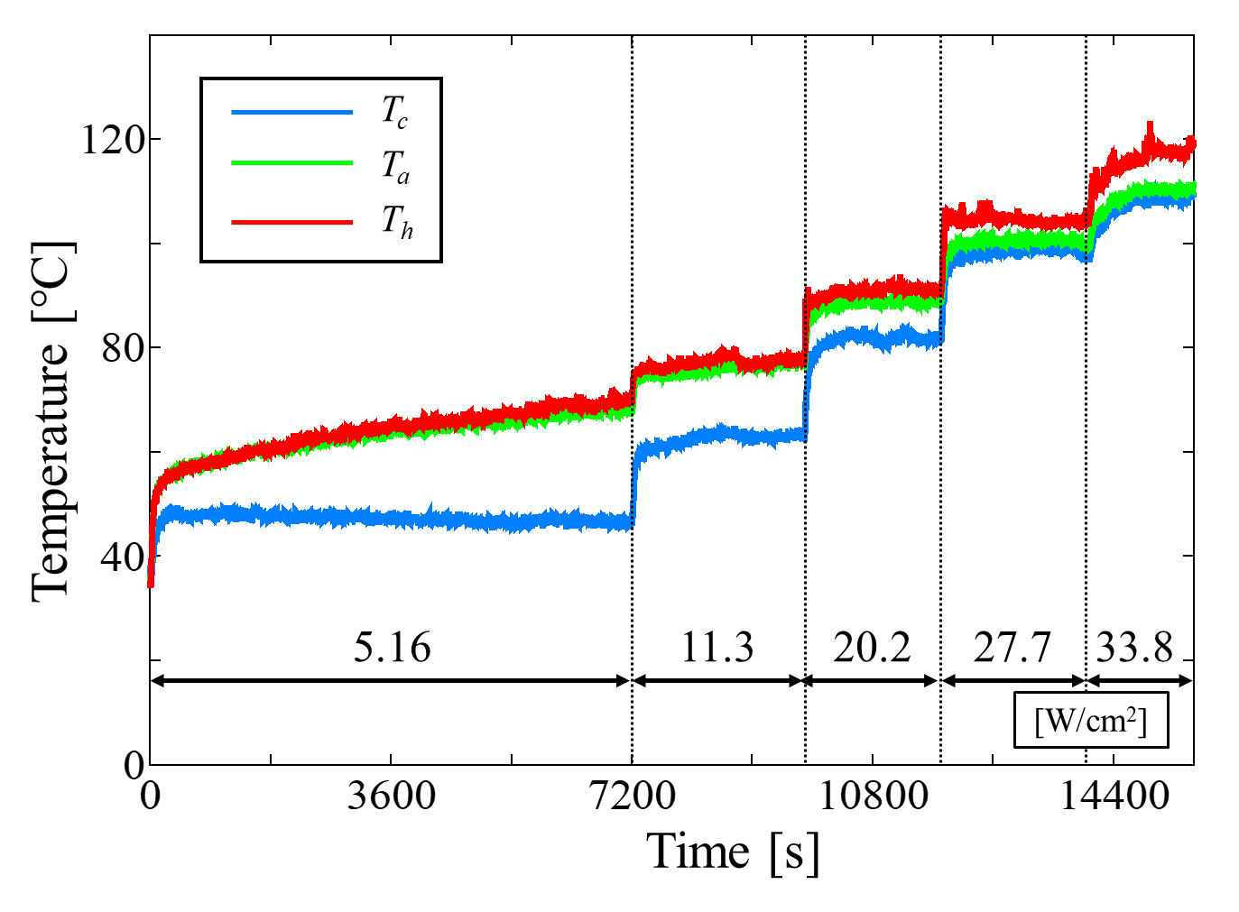
(a) 217 mL/min
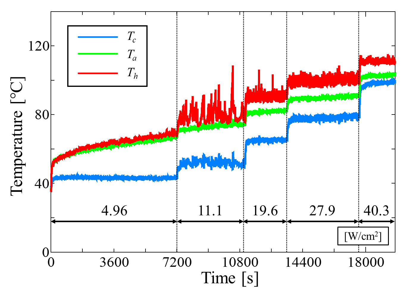
(b) 621 mL/min
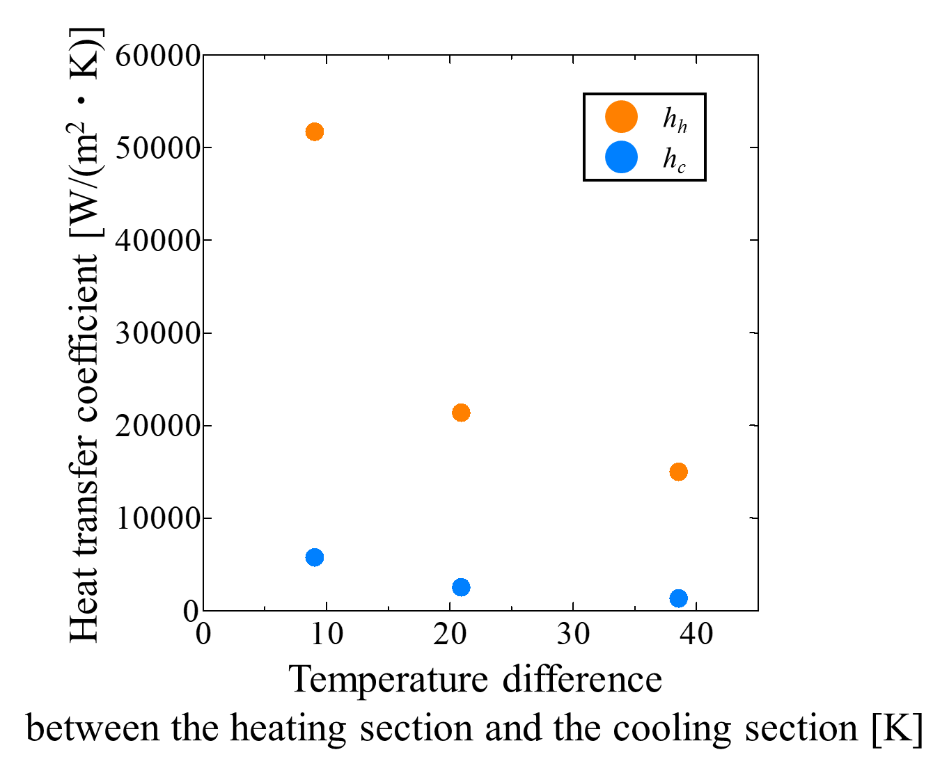
Figure 13 presents the condensation and evaporation heat transfer coefficients at each flow rate, with the horizontal axis representing the net heat flux. Both coefficients tended to decrease with increasing water flow rate. This is due to excessive cooling, which caused liquid retention in the cooling section (as discussed in Section 3.2.2). With increasing water flow rate, the wall temperature of the cooling section decreased, promoting condensation of the vapor inside the MLFHP. Although part of the generated liquid drained downward due to gravity, when the condensation rate exceeded the drainage capacity, the cooling section surface became covered with a liquid film, thereby reducing condensation heat transfer. Furthermore, in this state of liquid retention, the supply of liquid to the heating section was restricted, which also reduced evaporation heat transfer. In addition, Figure 13 shows that for both flow rate conditions, the condensation heat transfer coefficient increased monotonically with the net heat flux, whereas the evaporation heat transfer coefficient increased and then sharply decreased. These results indicate that increasing the water flow rate induced temperature oscillations and particularly affected evaporation heat transfer.
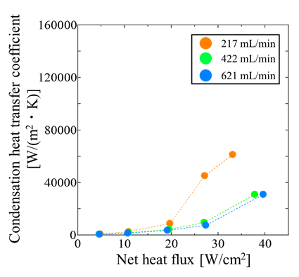
(a) Condensation heat transfer coefficients.
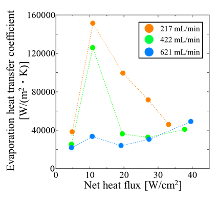
(b) Evaporation heat transfer coefficients.
3. 3. 3. Cooling Test at Constant Heat Input
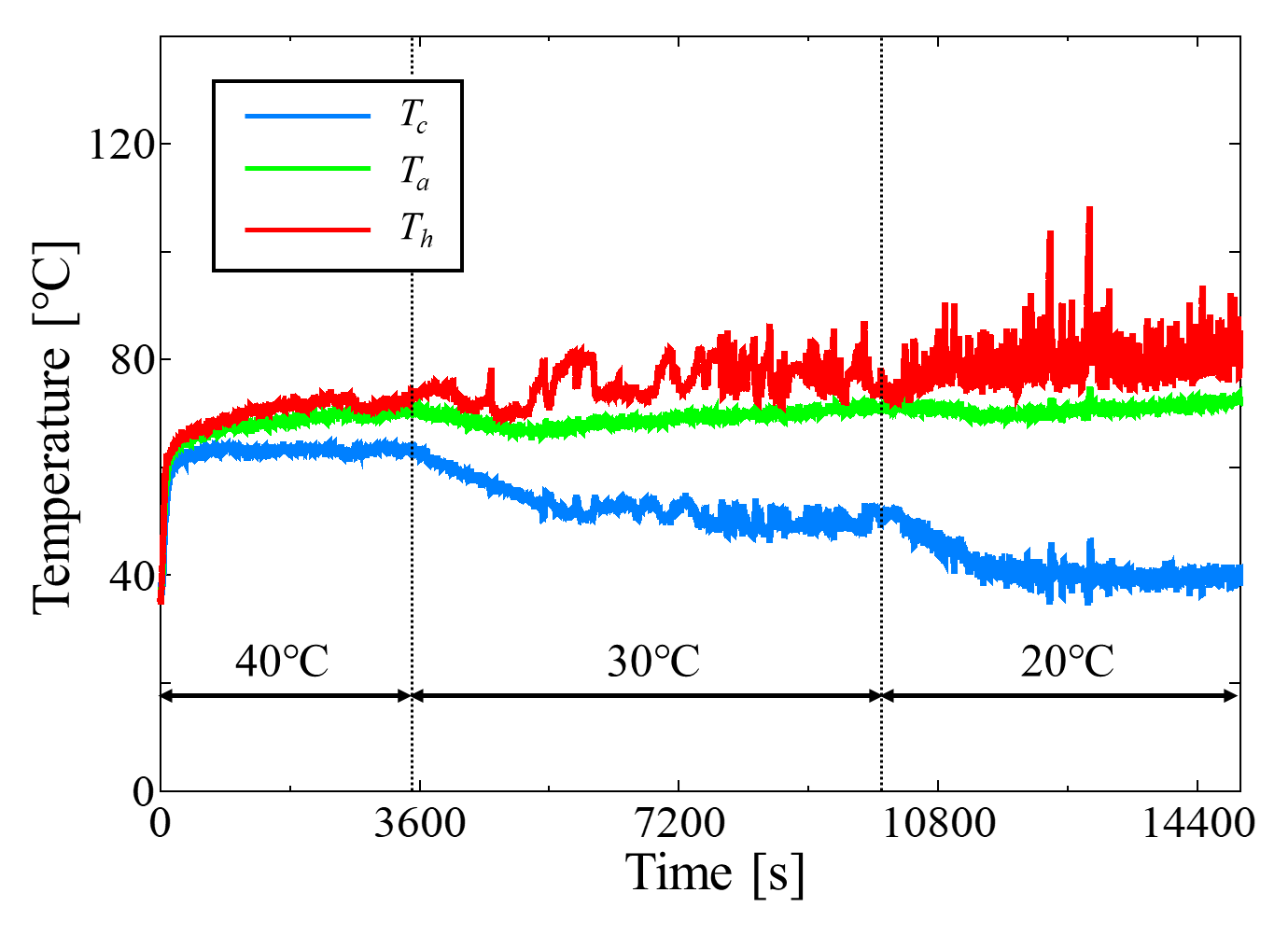
In the previous section, based on the heating test results, it was discussed that excessive cooling caused liquid retention in the cooling section, which restricted the liquid supply to the heating section. As a result, the evaporation heat transfer coefficient decreased and temperature oscillations occurred. In this section, to evaluate the influence of cooling conditions alone on the internal heat transfer characteristics of the MLFHP, experiments were conducted in which the heat input was kept constant while the cooling water temperature was varied. Figure 14 shows the temperature time histories at a net heat flux of 10.8 W/cm². The inlet temperature of the cooling water is also indicated in the figure. The water flow rate was fixed at 226 mL/min. As the cooling water temperature decreased, the cooling section temperature decreased, whereas the heating section temperature slightly increased. Consequently, the temperature difference between the heating and cooling sections widened. Along with this, temperature oscillations appeared, and the oscillation amplitude tended to increase at lower cooling water temperatures.
Figure 15 presents the evaporation and condensation heat transfer coefficients under varying cooling water temperatures, with the horizontal axis representing the temperature difference between the heating and cooling sections. Both coefficients decreased as the temperature difference increased. Since the heat input was kept constant, the amount of heat supplied to the heating section did not change. Therefore, the reduction in evaporation heat transfer coefficient was mainly attributed to changes in the cooling conditions of the condenser. It is thus inferred that lowering the cooling section temperature reduced the evaporation heat transfer coefficient and induced oscillations in the temperature behavior.
4. Conclusion
In this study, the thermal transport characteristics of the MLFHP under various cooling conditions were evaluated, focusing on its ability to suppress temperature rise at hotspots under high local heat flux conditions. Based on the overall results, the main conclusions of this study can be summarized as follows:
- At a filling ratio of 10 vol.%, the MLFHP exhibited significantly lower thermal resistance than at 50 vol.% under natural air cooling, achieving a minimum value of 0.16 K/W, which represents an 80% reduction compared to the conventional condition.
- Under forced air cooling, increasing air velocity improved the maximum allowable heat flux by approximately 24%. However, excessive cooling promoted condensation in the cooling section, leading to liquid retention and temperature oscillations in the heating section.
- Under water cooling with constant heat input, variations in the cooling water temperature significantly affected the evaporation heat transfer coefficient.
Overall, the MLFHP demonstrated excellent heat transport capability and high tolerance to heat flux. However, under strong cooling, condensation-induced oscillations were observed, indicating the need to optimize cooling intensity and filling ratio to achieve both effective heat removal and stable operation.
References
[1] R. J. McGlen, R. Jachuck, and S. Lin, "Integrated thermal management techniques for high power electronic devices," Applied Thermal Engineering, vol. 24, no. 8, pp. 1143-1156, June 2004. View Article
[2] A. Bar-Cohen, P. Wang, and E. Rahim, "Thermal management of high heat flux nanoelectronic chips," Microgravity Sci. Technol, vol. 19, no. 3, pp. 48-52, Oct. 2007. View Article
[3] D. Mangini, M. Mameli, A. Georgoulas, L. Araneo, S. Filippeschi, and M. Marengo, "A pulsating heat pipe for space applications: Ground and microgravity experiments," International Journal of Thermal Sciences, vol. 95, pp. 53-63, Sept. 2015. View Article
[4] A. Wei, J. Qu, H. Qiu, C. Wang, and G. Cao, "Heat transfer characteristics of plug-in oscillating heat pipe with binary-fluid mixtures for electric vehicle battery thermal management," International Journal of Heat and Mass Transfer, vol. 135, pp. 746-760, June 2019. View Article
[5] D. S. Jang, D. Kim, S. H. Hong, and Y. Kim, "Comparative thermal performance evaluation between ultrathin flat plate pulsating heat pipe and graphite sheet for mobile electronic devices at various operating conditions," Applied Thermal Engineering, vol. 149, pp. 1427-1434, Feb. 2019. View Article
[6] R. Dreiling, S. Zimmermann, M. Reibstirn, T. Nguyen-Xuan, P. Schreivogel, and F. Di Mare, "Experimental operating range evaluation of flat-plate pulsating heat pipes for high-heat flux automotive power electronics cooling," Applied Thermal Engineering, vol. 226, p. 120338, May 2023. View Article
[7] A. Zamanifard, M. Muneeshwaran, Y.-H. Wang, and C.-C. Wang, "A novel 3-D pulsating heat pipe module for high heat-flux applications," Applied Thermal Engineering, vol. 228, p. 120549, June 2023. View Article
[8] S. Shoeibi, H. Kargarsharifabad, M. Khiadani, and M. M. Rashidi, "Techno-enviro-exergo-economic evaluation of hot water production by waste heat recovery using U-shaped pulsating heat pipe - an experimental study," Energy Sources, Part A: Recovery, Utilization, and Environmental Effects, vol. 46, no. 1, pp. 3292-3308, Dec. 2024. View Article
[9] H. Akachi, "Structure of a heat pipe," US4921041A, May 01, 1990. View Article
[10] S. Rudresha, E. R. Babu, and R. Thejaraju, "Experimental investigation and influence of filling ratio on heat transfer performance of a pulsating heat pipe," Thermal Science and Engineering Progress, vol. 38, p. 101649, Feb. 2023. View Article
[11] Md. L. Rahman, T. Afrose, H. K. Tahmina, R. P. Rinky, and M. Ali, "Effect of using acetone and distilled water on the performance of open loop pulsating heat pipe (OLPHP) with different filling ratios," AIP Conf. Proc., vol. 1754, no. 1, p. 050015, July 2016. View Article
[12] Z. Li and L. Jia, "Experimental study on natural convection cooling of LED based on plate pulsating heat pipe," Heat Transfer Research, vol. 44, no. 1, 2013. View Article
[13] C. Czajkowski, A. I. Nowak, P. Błasiak, A. Ochman, and S. Pietrowicz, "Experimental study on a large scale pulsating heat pipe operating at high heat loads, different adiabatic lengths and various filling ratios of acetone, ethanol, and water," Applied Thermal Engineering, vol. 165, p. 114534, Jan. 2020. View Article
[14] H. Ahmad and S. Y. Jung, "Effect of active and passive cooling on the thermo-hydrodynamic behaviors of the closed-loop pulsating heat pipes," International Journal of Heat and Mass Transfer, vol. 156, p. 119814, Aug. 2020. View Article
[15] F. Shang, Q. Yang, C. Liu, S. Fan, and J. Liu, "An experimental study on heat transfer performance of a pulsating heat pipe radiator for CPU heat dissipation," E3S Web Conf., vol. 165, p. 06035, 2020. View Article
[16] X. Cui, Y. Zhu, Z. Li, and S. Shun, "Combination study of operation characteristics and heat transfer mechanism for pulsating heat pipe," Applied Thermal Engineering, vol. 65, no. 1, pp. 394-402, Apr. 2014. View Article
[17] W. Shi, X. Liu, X. Su, H. Chen, and L. Pan, "Influence of Cooling Water Flow Rate on Start and Heat Transfer Performance of Pulsating Heat Pipe at Different Inclination Angles," Sustainability, vol. 15, no. 3, p. 1921, Jan. 2023. View Article
[18] J. Kim and S. J. Kim, "Experimental investigation on the effect of the condenser length on the thermal performance of a micro pulsating heat pipe," Applied Thermal Engineering, vol. 130, pp. 439-448, Feb. 2018. View Article
[19] K. Fumoto and K. Ishii, "Flat plate pulsating heat pipe operating at ultra-low filling ratio," Applied Thermal Engineering, vol. 228, p. 120468, June 2023. View Article
[20] S. Tsutsumiuchi, K. Ishii, and K. Fumoto, "Basic research on heat transport characteristics of low filling ratio pulsating heat pipe (Effect of heat pipe installation posture on heat transport performance)," Transactions of the JSME (in Japanese), vol. 90, no. 930, pp. 23-00268, 2024. View Article
[21] A. Shiokawa, A. Hatamoto, and K. Fumoto, "Effect of working fluid on heat transfer characteristics of meander-shaped low-fill heat pipe," Journal of Thermal Science and Technology, vol. 20, no. 2, pp. 25-00165, 2025. View Article
[22] R. Senjaya and T. Inoue, "Effects of non-condensable gas on the performance of oscillating heat pipe, part II: Experimental study," Applied Thermal Engineering, vol. 73, no. 1, pp. 1393-1400, Dec. 2014. View Article