Journal of Fluid Flow, Heat and Mass Transfer (JFFHMT)
ISSN: 2368-6111

Volume 12 - Year 2025 - Pages 434-439
DOI: 10.11159/jffhmt.2025.043
Numerical Modeling of Density Wave Instability in Cryogenic Hydrogen Flow
Konstantin I. Matveev1
1Hydrogen Properties for Energy Research (HYPER) Center
Washington State University
Pullman, WA, 99164, USA
matveev@wsu.edu
Abstract - Liquid hydrogen is an attractive fuel for future green economy, as it does not result in harmful pollution and can be produced using renewable energy. However, liquid hydrogen requires very low cryogenic temperatures, and even small heat leaks can cause hydrogen to evaporate. When transferring liquid hydrogen, such boiling may lead to instabilities, including density wave oscillations, which make the transfer process unstable and can lead to the system damage. In this study, a one-dimensional model originating from basic fluid mechanics equations is developed and applied to predict the onset of density wave oscillations and their limit-cycle properties in a pipe flow setup. The time-domain evolution of oscillating flow properties and stability boundaries are calculated and presented for variable system parameters. The present findings can help engineers assess and mitigate this undesirable phenomenon in liquid hydrogen transfer devices.
Keywords: Cryogenic Systems, Liquid Hydrogen, Two-Phase Flow, Instabilities, Numerical Modeling.
© Copyright 2025 Authors - This is an Open Access article published under the Creative Commons Attribution License terms Creative Commons Attribution License terms. Unrestricted use, distribution, and reproduction in any medium are permitted, provided the original work is properly cited.
Date Received: 2025-06-27
Date Revised: 2025-11-23
Date Accepted: 2025-12-02
Date Published: 2025-xx-xx
1. Introduction
Since hydrogen does not emit harmful pollutants when reacting with oxygen, it is often considered as a major clean fuel for future economy [1]. However, to keep the hydrogen energy density acceptable for transportation means it must be kept in the liquid form which requires cryogenic temperatures [2]. During transfer of liquid hydrogen, heat leaks may cause partial boiling and result in various instabilities of two-phase fluid mixtures [3,4], including density wave oscillations (DWO), a subject of this study, which are common for more conventional steam systems [5]. Two-phase hydrogen boiling instabilities also occur during chill down processes, in evaporators, and when liquid hydrogen is used as a coolant for rocket engines. These instabilities may lead to unreliable fuelling, create safety risks, and cause structural damage. Thus, understanding and predicting of these oscillations in two-phase hydrogen flow is practically important.
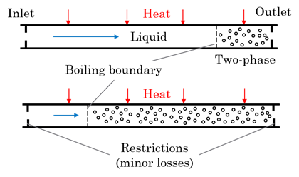
A number of studies of density wave oscillations in systems with more conventional fluids have been conducted in the past, reflected in reviews on this topic [6,7]. Examples of extensive experimental and computational studies can be found in [8,9]. The density wave oscillations appear due to coupling between various phenomena, including flow inertia, heat addition, phase change, and flow resistance. The increase of friction in two-phase flow relative to a liquid-phase case is especially important, as it leads to flow deceleration and higher evaporation, accompanied by even larger friction, thus creating positive feedback mechanisms that destabilize the flow. As a result, the flow in a pipe oscillates between states with high and low vapor content (Fig. 1), even at fixed boundary conditions.
Modeling approaches of DWO usually rely on numerical solutions of one-dimensional governing fluid mechanics equations, often with simplified treatment of the system properties [10,11]. Even more approximate lumped-element methods allow for computationally inexpensive predictions, albeit at the expense of lower accuracy and restricted parametric range [12].
In the present work, the distributed, one-dimensional approach is followed. The pipe flow system is discretised in the axial directions, and the governing equations are integrated in time to obtain a prediction time-domain evolution of the system, while using the real cryogenic hydrogen properties [13]. The developed model is described in the next section, followed by results for representative unsteady solutions, the limit-cycle magnitudes in the excited regimes, and stability boundary for setups with liquid hydrogen flow.
2. Mathematical Model
The considered configuration, shown in Figure 1, involves a pipe with two restrictions at the inlet and outlet. The pressure differential across the system drives the flow, while heat is externally supplied to the pipe leading to flow boiling. The following main assumptions are used in the model:
⦁ One-dimensional flow in a straight pipe
⦁ Homogeneous two-phase flow
⦁ Thermodynamic equilibrium between phases
⦁ No subcooled boiling
⦁ Effect of thermal wall inertia on heat addition is
ignored
⦁ Viscous heating and pressure terms are neglected in the energy equation
These assumptions affect the model accuracy, so proper validation must be performed to better understand the model limitations. (One validation case is presented below.) The homogeneous model ignores dependence of friction and heat transfer coefficients on different two-phase flow regimes that can be present at the same section-averaged flow quality. The wall thermal inertia may be important for setups with walls having large thermal mass and in transient scenarios. The ignored pressure terms are unlikely to have significant impact in most situations with relatively low-speed flow.
The governing continuity, momentum and energy equations can then be expressed as follows,

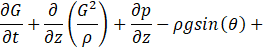

where ρ is the fluid density, G is the mass flux, t is the time, z is the coordinate along the tube, p is the pressure, g is the gravitational acceleration, θ is the tube angle with respect to horizontal, f is the friction factor, D is the tube diameter, Kin and Kout are the minor loss coefficients of the inlet and outlet restrictions, respectively, h is the specific enthalpy, q is the wall heat flux, and P and A are the perimeter and cross-sectional area of the pipe.
There are four variables in Eqs. (1-3), including density, mass flux, pressure, and enthalpy. The remaining equation to close the formulation is the equation of state. Here, the fluid density, enthalpy, and pressure are related using REFPROP software [13]. In most simulations presented below, parahydrogen is considered as the working fluid, while Freon-113 properties are used in the validation study, for which test data are available.
In addition, boundary conditions need to be defined at the inlet and outlet of the system. In this study, the pressure values are assigned at both boundaries, and the temperature or enthalpy of the subcooled liquid is given at the inlet. The initial conditions correspond to the steady flow of liquid through the pipe without heat addition. In the beginning of simulations, uniform wall heat flux is ramped up from zero to a given value over one second interval.
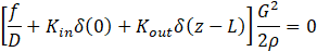
For the friction coefficient in Eq. (2), one of the common correlations is applied for the turbulent single-phase liquid flow in a smooth pipe [14], while the homogeneous equilibrium multiplier [15] is used for the two-phase flow,

where is the Reynolds number for pipe flow, x is the quality, vf and μf is the specific volume and viscosity of the saturated liquid, respectively, and vfg and μfg is the differences between these properties at the saturated vapor and liquid states.
Equations (1-3) are solved numerically using the finite-deference approach. The pipe is discretised into the nodes, including the inlet and outlet points. Pressure, density, and enthalpy are determined at the nodes, while mass fluxes are defined in the intervals between the nodes, following the common staggered arrangement. The convective derivatives are assessed using the upwind scheme, which depends on the local flow direction.
As the governing equations are nonlinear, an iterative algorithm is employed at each time step similar to that described in [16]. At each iteration, a linear system of equations is formed for variables G, p, and h by using the values from the previous iteration in the nonlinear terms for these variables and the fluid density. After that, the density is determined from new values of p and h using REFPROP. Then, the calculation is repeated with updated variables. The iterations continue until variables stop changing, and transition to a new time step is performed. Thus, a time-dependent solution is obtained, describing flow evolution in the system. In case of a stable operational condition, the system settles down to a steady flow solution. In unstable situations, the system variables exhibit oscillations.
3. Results and Discussion
To provide confidence in the employed model, a comparison with experimental data has been made. Although no test results on density wave oscillations exist for liquid hydrogen, there is experimental information for other fluids, such as freon-113 reported in [17]. The setup involved a vertical 3.5-m-long, 0.01-m-diameter tube with adiabatic initial section of length 0.8 m and uniformly heated downstream section at 12-bar mean pressure and outlet minor loss coefficient of 2.03. A comparison is shown in Table 1 in terms of commonly used for DWO the non-dimensional subcooling number and phase change number,
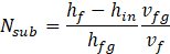
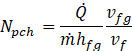
where hf is the specific enthalpy of the saturated fluid, hfg is the difference between enthalpies of the saturated vapor and liquid, ![]() is the rate of supplied heat, and
is the rate of supplied heat, and ![]() is the mass flow rate.
is the mass flow rate.
Table 1. Comparison of test and model results.
| Nsub | Kin | Npch | |
|
Test |
Model |
||
|
4.18 |
2.85 |
6.90 |
6.61 |
|
3.97 |
6.55 |
7.74 |
7.23 |
In the numerical simulation, the subcooling number and flow rate were kept the same as in the experiments, while the supplied heat (and therefore, the phase change number) was increased until non-attenuating oscillations were detected. An agreement for of about 6% is deemed sufficient for the approximate modeling under the imposed assumptions.
For demonstrating the application of the model for two-phase hydrogen flow, the default system parameters are selected as follows, mean pressure 3 bar, pressure drop 800 Pa, tube length 1 m, tube diameter 0.01 m, the inlet and outlet minor loss coefficients 1 and 10, respectively, and the horizontal tube orientation.
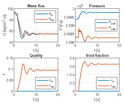
An illustration of time-domain results for this system in the stable regime with the inlet liquid temperature of 20 K and wall heat flux of 12.5 kW/m2 is given in Figure 2. The flow characteristics include the inlet and outlet mass fluxes, pressure recorded at 5% and 95% of the tube length from the inlet, and the inlet and outlet quality and void fraction. Upon the initial settling period, caused by transition of initial liquid flow to the two-phase flow in the downstream portion of the tube, the flow characteristics approach steady values.
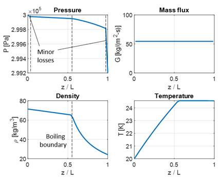
The distribution of flow variables along the tube in this steady-state regime are shown in Figure 3. One can note the concentrated pressure changes near the inlet and outlet, corresponding to restrictions at these locations. The pressure drop in the two-phase flow region is more pronounced than in the liquid portion due to higher friction coefficient (Eq. 5). The density variation in the two-phase zone is greater than in the liquid due to continuous phase change process (evaporation) in the downstream section of the tube. In contrast, temperature gradually increases in the liquid but stabilizes in the two-phase flow.
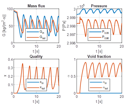
The same system can become unstable with increase of heating. An example of time-domain behaviour with wall heat flux of 13.0 kW/m2 is illustrated in Figure 4. Upon an initial transient period, the system reaches the limit-cycle regime with repeated oscillations in flow properties. Significant variations of all characteristics are noticed with the higher inlet mass flux amplitudes than that at the outlet, while more pressure variations are observed in the downstream part of the tube.
With further increase of the supplied heat, the oscillation amplitudes continue to grow. As the oscillations are not purely sinusoidal, the root-mean-square (RMS) values of the unsteady components are better representations of magnitudes of these fluctuations. They are quantified and presented in Figure 5 for the same system variable wall heat flux. The RMS values grow more significantly right after the transition to instability, but gradual saturation is noticed at larger values of supplied heat.
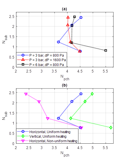
For practical applications, it is important to identify stability boundaries for quick assessment of DWO occurrence and their dependence on operational parameters. For the same hydrogen system, a stability boundary was calculated for several subcooling levels by varying heat flux. This boundary is shown by blue circles in Figure 6 using - coordinates. It has a common L-shape, requiring larger heat addition to trigger instability at both low and high values of subcooling, while minimizing needed heat at intermediate subcooling (about 2 K for the considered system).
The influence of several system variations on the stability boundary has been explored as well. Twice higher pressure drop across the system (leading to increase of flow rate) shifts the more favourable for instability subcooling to larger values (Figure 6a), while larger mean pressure makes it more difficult to excite DWO at low subcooling and easier at higher subcooling (Figure 6a). The vertical orientation of the pipe delays the instability to higher values of supplied heat for all subcooling levels (Figure 6b), as gravity counteracts the flow and supresses disturbances. Also investigated is the effect of non-uniform heating, concentrated in the middle of the pipe within , while the upstream and downstream pipe segments are not heated. This more intensive heating over shorter interval (the total heat supplied is kept the same) leads to stronger effect at larger subcooling by initiating instability at much lower values of the total supplied heat (Figure 6b), whereas its influence at low subcooling is found to be small.

4. Conclusion
A one-dimensional distributed model has been developed and applied for density wave oscillations in cryogenic hydrogen flow. Numerically obtained time-domain solutions at given system parameters allow us to determine whether the system is stable or exhibits nonlinear oscillations associated with frictional drag increase in two-phase flow. Increase of supplied heat with other parameters fixed leads to initiation of instability and gradual saturation of oscillation magnitudes. The stability diagrams in terms of the subcooling number and the phase change number demonstrates optimal subcooling level for initiation of instability. Increase of pressure drop and mean pressure lead to earlier excitation of instability but shows a stabilizing effect at low subcooling. The upward vertical flow is more stable than the horizontal, whereas concentrated heating can cause earlier excitation of DWO, especially at higher subcooling. Thus, the appropriate amount of subcooling, vertical pipe orientation, and more uniform heating are the important factors that can be utilized to prevent DWO occurrence.
The present model can be further extended by including the effect of thermal inertia of the pipe wall and time-variable heat flux at inlet flow conditions. The obtained results should be useful for the engineering community interested in developing robust liquid hydrogen transfer systems and improving safety of hydrogen systems in general. The developed model can be utilized in both the design process to choose system parameters that minimize chances of instabilities and for selecting stable operational regimes in existing systems.
Acknowledgement
This work was supported in part by the U.S. National Science Foundation under Grant No. 2214235.
References
[1] J. W. Leachman, Ø. Wilhelmsen and K. I. Matveev, Cool Fuel: The Science and Engineering of Cryogenic Hydrogen, Oxford: Oxford University Press, 2025. View Article
[2] B.P. Pedrow, S.K., Muniyal Krishna, E.D. Shoemake, J.W. Leachman and K.I. Matveev, "Parahydrogen-orthohydrogen conversion on catalyst-loaded scrim for vapor-cooled shielding of cryogenic storage vessels," Journal of Thermophysics and Heat Transfer, vol. 35, pp. 142-151, 2021. View Article
[3] J.C. Burke, W.R. Byrnes, A.H. Post and F.E. Ruccia, "Pressurized cooldown of cryogenic transfer lines," Advances in Cryogenic Engineering: Proceedings of the 1958 Cryogenic Engineering Conference, Boston, MA: Springer.
[4] M.P. Shenton, J.W. Leachman and K.I. Matveev, "Investigating Taconis oscillations in a U-shaped tube with helium and hydrogen," Cryogenics, vol. 143, 103940, 2024. View Article
[5] M. Colombo, A. Cammi, D. Papini and M. E. Ricotti, "RELAP5/MOD3. 3 study on density wave instabilities in single channel and two parallel channels," Progress in Nuclear Energy, vol. 56, pp. 15-23, 2012. View Article
[6] S. Kakaç and B. Bon, "A review of two-phase flow dynamic instabilities in tube boiling systems," International Journal of Heat and Mass Transfer, vol. 51(3-4), pp. 399-433, 2008. View Article
[7] C. Li, X. Fang and Q. Dai, "Two-phase flow boiling instabilities: A review," Annals of Nuclear Energy, vol. 173, 109099, 2022. View Article
[8] M. Ishii, Study of Flow Instability in Two-Phase Mixture, Argonne National Laboratory Report, ANL-76e23, 1976.
[9] L. E. O'Neill and I. Mudawar, "Review of two-phase flow instabilities in macro-and micro-channel systems," International Journal of Heat and Mass Transfer, vol. 157, 119738, 2020. View Article
[10] X. Lu, Y., Wu, L. Zhou, W. Tian, G. Su, S. Qiu and H. Zhang, "Theoretical investigations on two-phase flow instability in parallel channels under axial non-uniform heating," Annals of Nuclear Energy, vol. 63, pp. 75-82, 2014. View Article
[11] W. Ambrosini, P. Di Marco and J. C. Ferreri, "Linear and nonlinear analysis of density wave instability phenomena," International Journal of Heat and Technology, vol. 18(1), pp. 27-36, 2000.
[12] D. Papini, A. Cammi, M. Colombo, and M. E. Ricotti, "Time-domain linear and non-linear studies on density wave oscillations," Chemical Engineering Science, vol. 81, pp. 118-139, 2012. View Article
[13] E. W. Lemmon, I. H. Bell, M. L. Huber and M. O. McLinden, NIST Standard Reference Database 23: Reference Fluid Thermodynamic and Transport Properties-REFPROP, Version 10.0. Gaithersburg, MD: National Institute of Standards and Technology, Standard Reference Data Program, 2018.
[14] S. E. Haaland, "Simple and explicit formulas for the friction factor in turbulent flow," Journal of Fluids Engineering, vol. 105(1), pp. 89-90, 1983. View Article
[15] N. E. Todreas and M. S. Kazimi, Nuclear Systems I: Thermal Hydraulic Fundamentals. Washington: Taylor & Francis, 1993.
[16] L. C. Ruspini, C. A. Dorao and M. Fernandino, "Dynamic simulation of Ledinegg instability," Journal of Natural Gas Science and Engineering, vol. 2, pp. 211-216, 2010. View Article
[17] P. Saha, "Thermally induced two-phase flow instabilities, including the effect of thermal non-equilibrium between the phases," Ph.D. dissertation, School of mechanical Engineering, Georgia Institute of Technology, Atlanta, GA, 1974.