Journal of Fluid Flow, Heat and Mass Transfer (JFFHMT)
ISSN: 2368-6111

Volume 12 - Year 2025 - Pages 139-145
DOI: 10.11159/jffhmt.2025.015
Creeping Motion and Coalescence of Droplets Rising in a Vertical Tube filled with a Quiescent Fluid
Masahiro Muraoka1, Tsubasa Takamizawa1
1Tokyo University of Science, Department of Mechanical and Aerospace Engineering
2641 Yamazaki, Noda, Chiba, Japan 278-8510
masa@rs.tus.ac.jp; 7523541@ed.tus.ac.jp
Abstract - The creeping motion and coalescence of droplets rising in a vertical tube filled with a quiescent fluid are experimentally examined. The viscosity ratio of a droplet to the surrounding fluid is unity, keeping the undeformed diameter of the leading droplet constant while varying the kinematic viscosities of the droplet and surrounding fluid, as well as the diameter of the following droplet. The creeping motion of droplets can be divided into three types. The coalescence times of two droplets are measured. The diameter of the clearance area between them is also measured immediately before coalescence. The experimentally measured coalescence times are compared with the coalescence times of droplets predicted using a semi-theoretical formula. The forces acting on the thin film between the droplets are discussed.
Keywords: Coalescence, Droplet, Creeping motion, Vertical tube, Quiescent fluid.
© Copyright 2025 Authors - This is an Open Access article published under the Creative Commons Attribution License terms Creative Commons Attribution License terms. Unrestricted use, distribution, and reproduction in any medium are permitted, provided the original work is properly cited.
Date Received: 2025-05-30
Date Revised: 2025-03-04
Date Accepted: 2025-03-30
Date Published: 2025-04-28
1. Introduction
The creeping motion and coalescence of droplets rising in a quiescent fluid confined in a vertical cylindrical tube are potentially useful for different purposes including handling of fluids and control of chemical reactions. The phenomena are also the basis for analyzing the flow of multiphase fluids through porous media such as in enhanced oil recovery (e.g., [1]–[4]) and the breaking of emulsions in porous coalescers. We focus on a narrow passage in porous media, where if we assume the passage as a cylindrical tube, then the coalescence of droplets in a viscous fluid through the passage is the same as that through a cylindrical tube. There are many references on the phenomenon of droplet coalescence. For example, Ristenpart et al. [5] investigated the coalescence dynamics of two spreading droplets on a highly wettable substrate. Kumar et al. [6] investigated the coalescence dynamics of a droplet freely falling on a sessile droplet. Gao et al. [7] studied the coalescence of microdroplet swarms in microchannels. A broad range of experimental studies on the interaction and coalescence of deformable droplets and bubbles have been reviewed and compared to a quantitative theory [8]. There have been a few cases of investigating the coalescence of droplets in a tube, such as by Olbricht’s group [9], [10]. Aul and Olbricht proposed a semi-theoretical formula for the coalescence time of droplets in a creeping flow through a cylindrical tube [10]. The coalescence time is defined as the period between the instant when the relative velocity of the two droplets becomes zero after their apparent contact, and when coalescence occurs. Based on Aul and Olbricht’s semi-theoretical formula, Muraoka et al. [11] proposed other semi-theoretical formulas for the coalescence time in terms of the resistance experienced by a liquid droplet in a viscous flow through a cylindrical tube in the Stokes regime [12]. In this study, the coalescence times of two droplets as well as the diameter of the clearance area between them immediately before coalescence are measured. The experimentally measured coalescence times are compared with values predicted using a semi-theoretical formula. The forces acting on the thin film between the droplets are discussed.
2. Experiment
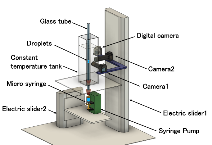
Figure 1 shows a schematic illustration of the experimental setup. A glass tube with an inner diameter of 3.5 mm, an outer diameter of 8.0 mm, and a length of 1500 mm was used as the test tube. The test tube was filled with a quiescent fluid which was a mixture of glycerol and pure water. The test tube was immersed in temperature-controlled water in a tank to maintain a constant system temperature. Silicone oils with kinematic viscosities of 30 cSt and 50 cSt were employed as the test fluids for the droplets. The viscosity of the droplets was equal to that of the surrounding fluid. Two droplets were injected into the test tube using a micro-syringe installed on a syringe pump placed in front of the tube inlet. The behavior of the droplets was monitored using three digital cameras placed on a sliding stage. The motion of the stage was electrically controlled to monitor the movement of the droplets through the test tube. The dimensionless undeformed diameter d1/D of the leading droplet was fixed at two values, 0.76 and 0.68, and the dimensionless undeformed diameter d2/D of the following droplet was varied, where d1 is the undeformed diameter of the leading droplet, d2 is the undeformed diameter of the following droplet, and D is the inner diameter of the test tube. The velocity of each leading and following droplet, the deviation from the tube central axis of each droplet and the coalescence time were measured. The diameters of the clearance area between them were also measured immediately before coalescence.
3. Semi-theoretical formula for coalescence time of droplets rising in quiescent fluid confined in vertical tube in Stokes regime
Based on the semi-theoretical formula of Aul and Olbricht [10], other semi-theoretical formulas for the coalescence time of droplets in a creeping flow through a tube have been proposed [11]. As shown in Figure 2, the clearance area between the leading droplet and the following droplet is assumed to be flat and discoid. Eq. (1) was derived from Reynolds’ theory of lubrication [13] under the assumption of two parallel-plane surfaces approaching each other.
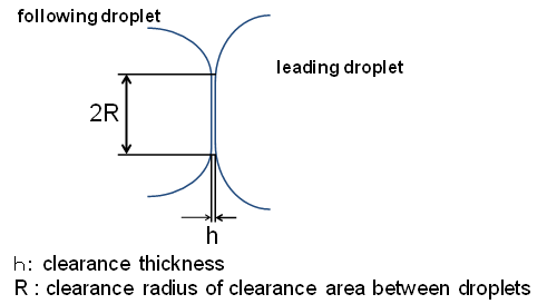

Here, F is the total force compressing the clearancearea between the droplets, h is the clearance thickness, R is the clearance radius of the clearance area between droplets (see Figure 2), and µs denotes the viscosity of the surrounding fluid. The total force F is expressed as the sum of the hydrodynamic force Fh and the van der Waals force between the droplets (Eq. (2)).

Here, A1 is the Hamaker constant. In this case, the hydrodynamic force decelerates the following droplet until the relative velocity of the two droplets becomes zero after their apparent contact. The hydrodynamic force can be expressed as F1 - F2, where F1 is the hydrodynamic force exerted on the following droplet when the velocity of the following droplet equals that of a single droplet without any interaction with the leading droplet, and F2 is the hydrodynamic force exerted on the following droplet when the relative velocity of the two droplets becomes zero after their apparent contact. Because the acceleration of the droplet was low, the virtual mass [14] was extremely small compared with the hydrodynamic force and thus not considered. The present experiments confirmed that the leading droplets stabilized before and after their apparent contact. Aul and Olbricht investigated the coalescence of droplets using a glass tube (inner diameter, 54 µm; length, 25 mm) and proposed a semi-theoretical formula for the coalescence time of droplets in a creeping flow through a tube. They defined the hydrodynamic force as the force exerted on a single rigid sphere after experimentally confirming that the velocity of the droplet was similar to that of the rigid sphere. In this study, F1 and F2 were determined using the numerical procedure developed by Higdon and Muldowney [12], who expressed the hydrodynamic force exerted on a single droplet in a creeping flow through a tube as


Here, F0 is the hydrodynamic force exerted on a single droplet in a creeping flow through a tube, η is defined in Eq. (4), μs is the viscosity of the surrounding fluid, d is the undeformed diameter of a single droplet, and Kz and Kp are the resistance coefficients [8]. In the reference, Kz and Kp are represented as Rz and Rp. Uz is the velocity of a single droplet, U0 is the maximum velocity of the parabolic pressure-driven flow, and β is the viscosity ratio of the droplet to that of the surrounding fluid. In Kz and Kp, the center-to-center distances between the droplets and tube axis are taken into consideration. The form of Eq. (3) is similar to that proposed by Haberman and Sayre [15]. Haberman and Sayre replaced the resistance acting on a sphere moving with velocity U in a creeping flow with the maximum velocity V through a cylindrical tube, with the resistance acting on a sphere fixed in a flow with a maximum velocity of V - U at the tube axis, where the tube wall moves at velocity U in the opposite direction to the flow. They expressed the resistance acting on the sphere in this case with the following equation.
Drag=6πμa( UK1-VK2 )=6πμaUK1-6πμaVK2
Here, K1 and K2 are wall correction coefficients, µ denotes the fluid viscosity, and a is the radius of the sphere. Therefore, the first term represents the resistance acting on a sphere moving at a velocity U in a quiescent fluid within a cylindrical tube, while the second term represents the resistance acting on a sphere fixed in a creeping flow with maximum velocity V inside the cylindrical tube. Substituting Eq. (3) for F1 and F2, the hydrodynamic force Fh can be expressed as shown in Eq. (6).

Here, Uz1 is the velocity of the following droplet without interaction with a leading droplet, Uz2 is the velocity of the following droplet when the relative velocity of the two droplets becomes zero after their apparent contact, and d2 is the undeformed diameter of the following droplet. Eq. (6) is an equation for the case where both the leading droplet and the following droplet move on the tube axis. That is, the density ratio between the droplets and the surrounding fluid is unity. With regard to the motions of the two droplets during the creeping flow through the cylindrical tube, as the following droplet became smaller in size, the effect of the secondary flow produced by the presence of the leading droplet caused it to move to an eccentric position. As the following droplet continued to decrease in size, it was more easily affected by the secondary flow. If the following droplet is located at an eccentric position, then Fh can be expressed using Eq. (7).

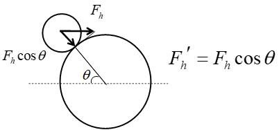
Here, Kz and Kp in the first braces are the resistance coefficients for the following droplet when the droplet position is not offset from the tube axis, and Kz and Kp in the second braces are the resistance coefficients for the following droplet when the droplet position is offset from the tube axis. As shown in Figure 3, the hydrodynamic force in this case can be denoted by Fhʹ, which is equal to Fh cosθ. Here, θ is the angle between the tube axis and the line joining the centers of the leading and following droplets.
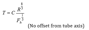
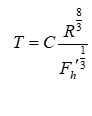
The coalescence time T can be calculated by integrating the numerator and denominator on the left-hand side of Eq. (1) using the method employed by Aul and Olbricht. Without considering the details of the integration process, the coalescence time T can be expressed using Eqs. (8) and (9). For simplicity, C is assumed to be constant in Eqs. (8) and (9), and its value can be determined experimentally.
When two droplets rise in a quiescent fluid confined in a vertical cylindrical tube, in Eqs. (3) and (5), the second term disappears, leaving only the first term. Eq. (3) is replaced by Eq. (10).
Substituting Eq. (10) for F1 and F2, the hydrodynamic force Fh can be expressed as shown in Eq. (11). Eq. (11) takes into account the deviation of the leading and following droplets from the tube central axis.
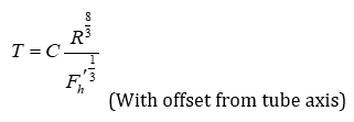
Here, Kz1 is the resistance coefficient for the following droplet when the following droplet is far from the leading droplet and there is no interaction between the droplets, whereas Kz2 is the resistance coefficient for the following droplet when the relative velocity of the two droplets becomes zero after their apparent contact. Kz1 and Kz2 are coefficients that take into account the offset from the tube axis. As shown in Figure 4, the hydrodynamic force in this case can be denoted by Fhʹ, which is equal to Fh cosθ. Here, θ is the angle between the vertical straight line and the line joining the centers of the leading and following droplets. The coalescence time T can be expressed by Eq. (12) in a similar manner to Eqs. (8) and (9).

4. Results and Discussion
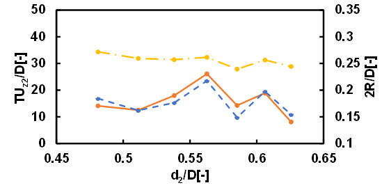
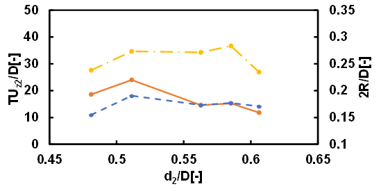
The motion of droplets rising in a quiescent fluid confined in a vertical cylindrical tube in the Stokes regime could be classified into three types: type 1 where both leading and following droplets rise almost straight, type 2 where the leading droplet rises almost straight while the following droplet undergoes spiral motion, and type 3 where the both leading and following droplets undergo spiral motion. In the case where d1/D=0.76 and the kinematic viscosity of the droplets is 30 cSt or 50 cSt, approximately 60% of the motion of droplets was type 1. The motions classified as type 2 and type 3 each accounted for approximately 20%. In the case where d1/D=0.68 and the kinematic viscosity of the droplets is 30 cSt, 15% of the motion of droplets was type 1, 10% of the motion of droplets was type 2 and 75% was type 3. When the size of the leading droplet was small, the difficulty of the mobility of the leading droplet due to the constraint of the cylindrical wall decreased, and the type 1 motion decreased and the type 3 motion increased. In the case where d1/D=0.68 and the kinematic viscosity of the droplets is 50 cSt, 36% of the motion of droplets was type 1, 13% of the motion of droplets was type 2 and 51% was type 3. When the size of the leading droplet was small, it is considered that as the viscosity of the droplet and the surrounding fluid increased, the mobility of the leading and following droplets decreased, resulting in an increase in type 1 motion and a decrease in type 3 motion. Figures 5 and 6 show the dimensionless coalescence times and dimensionless clearance diameter between the droplets as functions of the dimensionless undeformed diameter of the following droplet for different values of the kinematic viscosity of the droplets. d1/D was fixed at 0.76. T is the coalescence time, and R is the radius of the clearance area between the droplets. The solid lines represent the experimentally measured coalescence times. The dotted lines represent the semi-theoretical formula for the coalescence time, whereas the dash-dotted lines represent the dimensionless clearance diameters. The dimensionless coalescence time indicates how many tube diameters the two droplets travel during the coalescence time. The experimentally measured coalescence times for the droplets were in close agreement with the values predicted using the semi-theoretical formula. The trend for the clearance diameter was the same. Meanwhile, the effect of the clearance radius was greater than that of the hydrodynamic force, since the power of the clearance radius was much higher than that of the hydrodynamic force (see Eq. (12)).
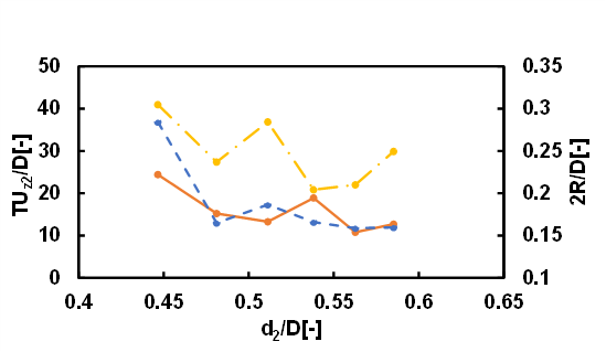
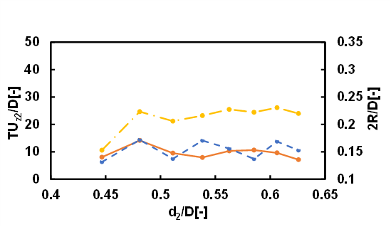
Figures 7 and 8 show the case where d1/D was fixed at 0.68. As in Figures 5 and 6, the experimentally measured coalescence times for the droplets were in close agreement with the values predicted using the semi-theoretical formula.
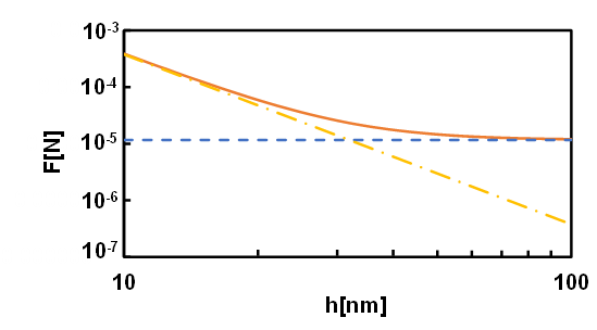
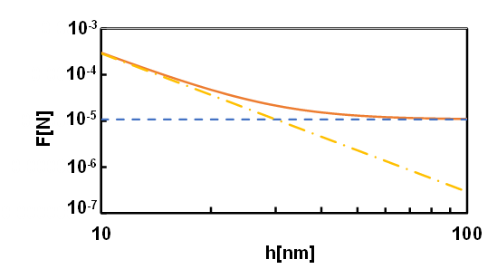
Figures 9 and 10 show the forces acting on the clearance area as a function of the clearance thickness for different kinematic viscosities of the droplets. Specifically, the figures show the cases for d1/D = 0.76 and d2/D = 0. 48, respectively. The solid lines represent the total force acting on the clearance area between the droplets, the dotted lines represent the hydrodynamic force Fhʹ, and the dash-dotted lines represent the van der Waals force between the droplets (see Eqs. (2), (11) and Figure 4). For Eq. (2), we assume that the Hamaker constant is 10-20 J. The hydrodynamic force Fhʹ is constant regardless of the clearance thickness h. However, the van der Waals forces between the droplets increase as the clearance thickness decreases. When the clearance thickness was larger than about 30 nm, the hydrodynamic force was dominant; when it was smaller than 30 nm, the van der Waals force between the droplets was larger than the hydrodynamic force. A comparison of the abovementioned figures shows that the kinematic viscosity of the droplets changed slightly.
5. Conclusion
The creeping motion and coalescence of droplets rising in a vertical tube filled with a quiescent fluid was examined in this study. The motion of droplets could be classified into three types: type 1 where both leading and following droplets rise almost straight, type 2 where the leading droplet rises almost straight while the following droplet undergoes spiral motion, and type 3 where both leading and following droplets undergo spiral motion. In the case where d1/D=0.76 and the kinematic viscosity of the droplets is 30 cSt or 50 cSt, approximately 60% of the motion of droplets was type 1. In the case where d1/D=0.68, when the kinematic viscosity of the droplets was 30 cSt, 15% of the motion of droplets was type 1, and when the kinematic viscosity of the droplet was 50 cSt, 36% of the motion of droplets was type 1. In the case of type 1 motion, a semi-theoretical formula for the coalescence time of droplets was obtained. The experimentally measured coalescence times for the droplets were in close agreement with the values predicted using the semi-theoretical formula. When the clearance thickness was larger than about 30 nm, the hydrodynamic force was dominant; when the clearance thickness was smaller than about 30 nm, the van der Waals force between the droplets was larger than the hydrodynamic force.
Acknowledgements
The authors wish to express their sincere gratitude to the students for their assistance with the experiments.
References
[1] K.S. Lee, J. Cho and J.H. Lee, CO2 Storage Coupled With Enhanced Oil Recovery. Springer, 2020. View Article
[2] P.M. Jarrell, C.E. Fox, M.H. Stein, and S.L. Webb, Practical Aspects of CO2 Flooding. Soc. Petroleum Eng., 2002. View Article
[3] J.J. Sheng, Enhanced Oil Recovery Field Case Studies. Elsevier, 2013.
[4] J.J. Sheng, Modern Chemical Enhanced Oil Recovery. Elsevier, 2011.
[5] W.D. Ristenpart, P.M. McCalla, R.V .Roy, and H.A .Stone, "Coalescence of Spreading Droplets on a Wettable Substrate," Phys. Rev. Lett. 97, 2006, 061501. View Article
[6] M. Kumar, R. Bhardwaj and K.C. Sahu, "Coalescence dynamics of a droplet on a sessile droplet," Phys. Fluids, 32, 2020, 012104. View Article
[7] C. Gao, S. Ling, Z. Chen, Y. Wang and J. Xu, "Coalescence law of microdroplet swarms in microchannels", Chem. Eng. Sci., 262, 2022, 118055. View Article
[8] D.Y.C. Chan, E. Klaseboer and R. Manica, "Film drainage and coalescence between deformable drops and bubbles," Soft Matter, 7, 2011, pp.2235-2264. View Article
[9] W.L. Olbricht and D.M. Kung, "The Interaction and Coalescence of Liquid Drops in Flow through a Capillary Tuibe," J. Collid Interface Sci., 120, No.1, 1987, pp. 229-244. View Article
[10] R.W. Aul and W.L. Olbricht, "Coalescence of Freely Suspended Liquid Droplets in Flow through a Small Pore," J. Colloid Interface Sci., 145, No. 2, 1991, pp.478-492. View Article
[11] M. Muraoka, T. Kamiyama, T. Wada, I. Ueno and H. Mizoguchi, "Coalescence Phenomena of Droplets with Suspended Particles in a Tube Creeping Flow," in Proceedings of the 8th World Conference on Experimental Heat Transfer, Fluid Mechanics and Thermodynamics, 2013, Paper No. 96.
[12] J.J.L. Higdon and G.P. Muldowney, "Resistance Function for Spherical Particles, Droplets and Bubbles in Cylindrical Tubes," J. Fluid Mech., 298, 1995, pp.193-210. View Article
[13] O. Reynolds, "On the Theory of Lubrication and its Application to Mr. Beauchamp Tower's Experiments Including an Experimental Determination of the Viscosity of Olive Oil," Phil. Trans. R. Soc. Lond., 177, 1886, pp. 157-234. View Article
[14] B.U. Felderhof, "Virtual mass and drag in two-phase flow," J. Fluid Mech., 225, 1991, pp.177-196. View Article
[15] W.L. Haberman and R.M. Sayre, "Motion of rigid and fluid spheres in stationary and moving liquids inside cylindrical tubes," David Taylor Model Basin Report No.1143. U.S. Navy Department, 1958. View Article