Journal of Fluid Flow, Heat and Mass Transfer (JFFHMT)
ISSN: 2368-6111

Volume 12 - Year 2025 - Pages 83-87
DOI: 10.11159/jffhmt.2025.008
Improving Oil Cooling Efficiency Using Polymeric Hollow Fibers
Filip Lang1, Erik Bartuli1*, Jiří Hvožďa1, Tereza Kroulíková1, Martin Beran2, Jiří Kučera3
1Heat Transfer and Fluid Flow Laboratory, Faculty of Mechanical Engineering, Brno University of Technology
Technická 2896/2, 616 69, Brno, Czech Republic
Erik.Bartuli1@vut.cz; Jiri.Hvozda@vut.cz; Tereza.Kroulikova@vut.cz
2Heat Transfer and Fluid Flow Laboratory, Institute of Automotive Engineering, Brno University of Technology
Technická 2896/2, 616 69, Brno, Czech Republic
beran.m@fme.vutbr.cz
3Hanon Systems Autopal s.r.o.
Závodní 1007, 687 25, Hluk, Czech Republic
jkucera@hanonsystems.com
Abstract - Oil cooling plays a critical role across various industries, such as transformer cooling, automotive, computing, and aerospace. This study introduces an innovative approach to oil cooling, utilizing a thin-walled polymeric hollow fiber heat exchanger. Research mainly focuses on oil cooling in combustion engines, which represent one of the most widespread applications. The designed cooling system is highly adaptable for a wide range of applications. The presented solution offers an attractive alternative characterized by low energy consumption, reduced CO2 emissions, and high specific heat transfer performance. The innovative approach lies in the use of polymer hollow fibres instead of standard aluminium heat exchangers. This strategy also saves space in the engine compartment as the heat exchanger is located in the engine oil sump. This heat exchanger is manufactured from polyamide (PA612) with an outer fiber diameter of 1 mm. Despite the low thermal conductivity of PA612, the polymeric hollow fibre heat exchanger has low thermal resistance owing to its thin wall thickness of only 0.08 mm. The proposed solution underwent rigorous testing on a combustion engine test rig capable of simulating real-world engine operating conditions. The results show that the designed cooling system achieved thermal outputs up to almost 1250 W (with a water flow rate of 1.5 l·min-1 in the heat exchanger). The engine coolant temperatures did not exceed 83.5 °C, remaining within the standard limits. Thus, the proposed system fulfils its function as an oil cooling system.
Keywords: Polymeric hollow fiber, Heat exchanger, Oil cooler.
© Copyright 2025 Authors - This is an Open Access article published under the Creative Commons Attribution License terms Creative Commons Attribution License terms. Unrestricted use, distribution, and reproduction in any medium are permitted, provided the original work is properly cited.
Date Received: 2024-12-23
Date Revised: 2025-02-04
Date Accepted: 2025-02-24
Date Published: 2025-03-04
1. Introduction
The main purpose of the oil system in a combustion engine car is to lubricate the moving parts in the engine and prevent wear, especially in bearings and shafts. However, the engine oil also performs a cooling function for some components. Conventional oil cooler design uses mostly finned plate heat exchangers. In this system, the oil heated by the engine is directed to a plate heat exchanger, where heat is transferred from the oil to the automotive coolant. Then, the cooled oil is returned to the engine. Excessively high oil temperatures have a detrimental effect on the overall performance and life of the engine. High oil temperature is also a direct indication of high engine temperature and, hence, an inefficient engine cooling system [1].
With the development of electromobility, the potential of oil cooling in the electric vehicle industry is becoming apparent. Studies [2] and [3] use immersion oil cooling for battery modules, investigate the effects of different types of oils for this application and present their potential for further use. Study [4] investigates the use of cooling oil spray for cooling high-speed electric motors.
Utilizing polymeric materials for heat exchangers in cooling systems presents several benefits compared to traditional metallic materials. Besides being more cost-effective, they are easier to shape and process, with a 4–5 times lower density. This results in cost reductions not only in construction but also in transportation and installation. Another benefit is their energy efficiency, the production of polymeric materials requires approximately half the energy compared to standard metallic materials. A significant environmental advantage is evident as well, with the production of a unit mass of polypropylene generating five times less CO2 than aluminum [5–6].
One limitation of polymers in heat exchanger applications is their low thermal conductivity. For instance, according to source [7], polyamide 6 (PA6) has a thermal conductivity of only 0.27 W·m−1·K−1 at 100 °C, and polypropylene (PP) at the same temperature is reported to have a value of 0.20 W·m−1·K−1. In contrast, metallic materials commonly used in heat exchanger manufacturing exhibit much higher thermal conductivities, e.g., aluminum reaches 236 W·m−1·K−1 at 0 °C, and copper even reaches 401 W·m−1·K−1 at 0 °C. To reduce the thermal resistance of polymers, fillers such as metallic particles (aluminum, copper, nickel, silver, etc.), carbon, or ceramic fillers can be added. However, this approach leads to costlier production and adversely affects the strength of the polymeric wall. Therefore, a more suitable method to decrease the thermal resistance of the exchanger wall is to reduce the thickness of the heat transfer surface. By reducing the thickness of the heat exchanger wall, the low thermal conductivity of the polymer is compensated and the thermal resistance of the polymer heat exchanger wall is comparable with metal heat exchanger wall [8].
The use of thin-walled polymeric heat exchangers has been demonstrated in several studies involving polymeric hollow fibers with outer diameters ranging from 0.8 to 1.2 mm and wall thicknesses between 10 to 15 % of the fiber's external diameter. These heat exchangers were tested in [9], which included a comparative analysis with traditional metal car engine coolers. Two heat exchangers made of polymeric hollow fibers with outer diameters of 0.6 mm and 0.8 mm were produced. A mixture of 50 % ethylene glycol and 50 % water at 60 °C entered the fibers, while air at 20 °C flowed around them. These exchangers achieved heat transfer coefficients up to 335 W·m−2·K−1 and a total thermal output of up to 10.2 kW. A specific comparison between a polymeric cooler made of hollow fibers and an aluminum cooler was presented in the study [10]. The polymeric cooler achieved up to 20 % higher thermal performance and was 20 % lighter than the aluminum cooler. Similarly, polymeric fiber exchangers can be used in applications with aggressive working media, leveraging their excellent chemical resistance. Such an application was described in [11] and [12], where polymeric fibers were used for water desalination.
2. Experimental Section
The heat exchanger testing took place at a specialized facility designed to simulate the operational conditions of an automotive engine, specifically focusing on the VW EA211EVO 1.5TSI 96 kW engine model. This engine uses a metal plate heat exchanger (Fig. 1) - measuring about 150 × 87 × 42 mm - mounted in the engine compartment to remove excess heat from the oil. In this study, that standard external metal heat exchanger was removed, and only the newly designed polymer heat exchanger, placed directly in the oil sump, was used. One of the primary motivations for this configuration was to free up valuable space under the hood by eliminating the external cooler, which is especially beneficial in modern engines with very tight packaging constraints.
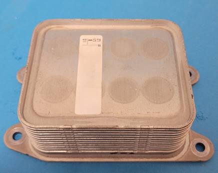
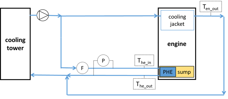
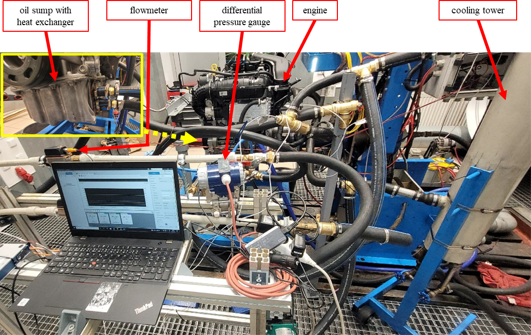
Fig. 2 illustrates the schematic of the experimental setup. The experimental setup (Fig. 3) consists of a cooling tower, a differential pressure gauge, Pt100, a water pump, a flowmeter, and a heat exchanger placed in the engine's oil sump. The cooling tower simulates the function of an automotive radiator in the engine cooling circuit. Typically, in vehicles, heat from the working fluid is dissipated via a radiator located at the front of the car, where it is cooled by airflow. In this radiator, heat is thus removed from the working medium, resulting in a reduction of the medium's temperature. In this experimental circuit, this function is performed by a cooling tower that can simulate a real car radiator. The coolant, cooled to a defined temperature, then flows to the engine where it splits the flow into two separate branches. The first branch cools the engine by the cooling jacket located in the engine. This branch has not been modified in the experiments. The second branch uses a designed heat exchanger located in the oil bath to cool the engine oil. This heat exchanger replaces the conventional metal heat exchanger that was also located in a separate branch.
A flowmeter SV4204 was used to measure flow. All temperatures were measured using a Pt100 resistor temperature detectors with an accuracy of 1/3 DIN, i.e. ± (0.10 + 0.0017·abs(t)) °C. For measuring pressure loss, a differential pressure gauge XMD with an accuracy of ± 0.1 % was employed.
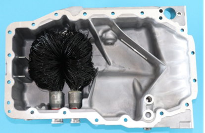
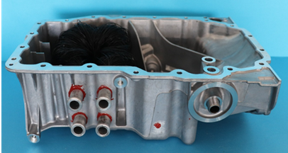
A polymeric heat exchanger constructed of hollow fibers was used in the experiment and placed in the engine oil sump, as shown in Fig. 4. This heat exchanger consisted of two distinct sections, containing a total of 240 fibers, each with a length of 470 mm. The polymeric fibers used in the heat exchanger were extruded from Polyamide 612 (PA612), with an inner diameter of 0.84 mm and an outer diameter of 1 mm. PA612 was selected primarily for its combination of chemical resistance and mechanical strength at elevated temperatures. Compared to alternatives like polypropylene (PP) or polybutylene terephthalate (PBT), PA612 withstands higher operating temperatures (up to 140°C ) with less long-term degradation. Additionally, it strikes a balance between flexibility (important for thin-walled fiber fabrication) and sufficient stiffness. PA612 is also widely available in the market at a relatively low cost, making it a cost-effective choice for automotive applications.
The experiment was conducted under the following parameters: The cooling tower regulated the temperature of the cooling fluid (which was water) to 70 °C before it entered into the heat exchanger. The flow rate in the heat exchanger was set at 1.5 l/min. This flow rate is lower than in the original metal heat exchanger used for oil cooling. But for a polymer heat exchanger, it should provide sufficient cooling and at the same time reduce the pressure losses in the polymer heat exchanger. Engine speed and load were varied during the measurement process. Engine speeds were sequentially set to 2000, 2500, and 3000 revolutions per minute (rpm). This representative range of rpm was chosen because it can simulate the engine's behaviour even at the highest torque available (200 Nm). The engine load (torque ratio) was sequentially set using a engine dynamometer to values of 0.3, 0.5, and 1. The speed and load points chosen for the experiment reflect the selected engine operating conditions during the WLTP emission cycle (i.e., predominantly lower and medium engine loads).
3. Results and Discussion
A critical parameter for the proper functioning of the engine is the coolant temperature at the engine's outlet. An increase in this temperature would indicate insufficient heat removal from the oil. The operating medium's temperature peaked at 83.5°C under conditions of 3000 rpm engine speed and an 100% engine load. This temperature falls within the conventional temperature range for the working medium of a combustion engine.
Although the present results demonstrate that the system provides efficient cooling, we observed a relatively high pressure drop of about 66 kPa. While this is significant, it remains within acceptable ranges for auxiliary automotive circuits. This primarily stems from the fact that the tested setup was our first prototype, deliberately designed to be oversized for initial evaluations. First, the fibers were made longer than strictly necessary to test whether they might snag or tear on any moving parts. Second, the heat exchanger was rated for a higher cooling capacity than actually required, allowing us to confirm that the overall technology works as intended.
For future iterations, we plan to use a greater number of fibers while roughly halving their length. Because fluid pressure losses in a channel depend heavily on channel length and flow velocity, this adjustment could potentially reduce the pressure drop by at least twofold. Meanwhile, the total heat transfer area will remain largely unchanged due to the increased number of fibers. As a result, subsequent generations of this device should exhibit substantially lower pressure losses while retaining overall cooling performance.
The measured data also shows that the temperature of heat exchanger input changes during the measurement from 71.3 to 73 °C. This is due to the hysteresis of the cooling tower, which could not cool the heated medium fast enough. This phenomenon slightly decreased the cooling effect in the designed heat exchanger.
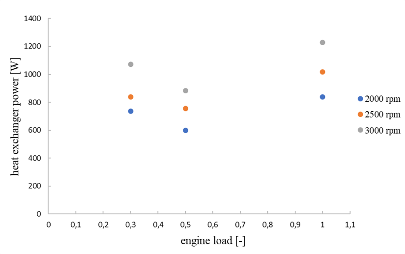
Fig. 5 illustrates dependence between the heat exchanger's thermal power and its load and speed. The thermal output varied between 598 and 1228 W at the engine's maximum load and a speed of 3000 rpm. The graph clearly shows that increasing the engine load from 0.3 to 0.5 leads to a reduction in the thermal performance of the polymeric exchanger. This phenomenon is due to the cooling circuit within the engine having a more significant impact on the overall engine cooling within this range.
4.Conclusion
In this study, the feasibility of replacing the conventional metal oil cooler in combustion engine vehicles with a polymeric hollow fiber heat exchanger was investigated. This alternative is characterized by lower energy requirements for production, reduced CO₂ emissions, and high specific heat transfer performance, making it an attractive option compared to traditional heat exchangers. Based on the presented results, it is evident that thin-walled polymeric exchangers can effectively function as oil coolers in cars. The highest critical temperature (the temperature at the engine outlet) was 83.5 °C at the engine’s maximum load and 3000 rpm - well within typical engine operating values - confirming that the polymeric exchanger performs its cooling function properly. The heat exchangers achieved performance values ranging from 598 W to 1228 W.
An additional advantage of our design is that the polymeric heat exchanger is fully immersed in the engine’s oil sump, whereas a standard metal oil cooler is mounted externally and requires its own dedicated space in the engine compartment. For instance, a typical factory-installed metal oil cooler for a Škoda Octavia measures roughly 150 × 87 × 42 mm, adding significant bulk to an already crowded under-hood area. Eliminating that external unit helps free up valuable space and simplifies packaging - an important consideration in modern vehicle design.
Future work should focus on a detailed comparison of the conventional and proposed cooling systems and on optimizing the proposed cooling system.
Acknowledgements
This work was supported by "Hollow Fiber Heat Exchangers with Reduced Permeability for Smart Cities", funded as project No. 8I24002 by Programme EIG CONCERT by Ministry of Education, Youth and Sports and the internal grant of the Brno University of Technology focused on specific research and development No. FSI-S-23-8254.
References
[1] O. P. Singh, M. Garg, V. Kumar and Y. V. Chaudhary, "Effect of Cooling System Design on Engine Oil Temperature," Journal of Applied Fluid Mechanics, vol. 6, no. 1, pp. 61-71, 2013. View Article
[2] J. Liu, H. Chen, M. Yang, S. Huang, K. Wang, "Comparative study of natural ester oil and mineral oil on the applicability of the immersion cooling for a battery module, " Renewable Energy, vol. 224, 2024. View Article
[3] W. Cheng, M. Chen, D. Ouyang, J. Weng, L. Zhao, Y. Chen, "Investigation of the thermal performance and heat transfer characteristics of the lithium-ion battery module based on an oil-immersed cooling structure," Journal of Energy Storage. vol. 79, 2024. View Article
[4] X. Wang, Y. Yan, Y. Li, "Study on high-speed electric motor cooling with oil spray," e-Prime - Advances in Electrical Engineering, Electronics and Energy , vol. 4, 2023. View Article
[5] X. Chen, Y. Su, D. Reay, S. Riffat, "Recent research developments in polymer heat exchangers," Renewable and Sustainable Energy Reviews, vol. 60, pp. 1367-1386, 2016. View Article
[6] D. M. Zarkadas, K. K. Sirkar, "Polymeric Hollow Fiber Heat Exchangers: An Alternative for Lower Temperature Applications", Ind. Eng. Chem. Res., vol. 43, pp. 8093-8106, 2004. View Article
[7] VDI Heat Atlas. Berlion: Springer, 2010.
[8] A. R. J. Hussain, A. A. Alahyari, S. A. Eastman, C. Thibaud-Erkey, S. Johnston, M. J. Sobkowicz, "Review of polymers for heat exchanger applications: Factors concerning thermal conductivity," Applied Thermal Engineering, vol. 113, pp. 1118-1127, 2017. View Article
[9] I. Krásný, I. Astrouski, M. Raudenský, "Polymeric hollow fiber heat exchanger as an automotive radiator," Applied Thermal Engineering, vol. 108, pp. 798-803, 2016. View Article
[10] T. Kroulíková, T. Kůdelová, E. Bartuli, J. Vančura, I. Astrouski, "Comparison of a Novel Polymeric Hollow Fiber Heat Exchanger and a Commercially Available Metal Automotive Radiator," Polymers, vol. 13, no. 7, 2021. View Article
[11] S. Song, H. Shan, J. Liu, B. Li, "Heat transfer study of PVDF hollow fiber heat exchanger for desalination process,". Desalination, vol. 446, pp. 1-11, 2018. View Article
[12] Song, L., Li, B., Zarkadas, D., Christian, S., Sirkar, K.K.: Polymeric Hollow-Fiber Heat Exchangers for Thermal Desalination Processes," Ind. Eng. Chem. Res., vol. 49, pp. 11961-11977, 2010. View Article