Journal of Fluid Flow, Heat and Mass Transfer (JFFHMT)
ISSN: 2368-6111

Volume 12 - Year 2025 - Pages 28-38
DOI: 10.11159/jffhmt.2025.004
Experimental Validation of a Design Method for Small Scale Pillow Plate Heat Exchangers
Alessandro Dai Pré1, Luca Marchetto2*, Maurizio Grigiante2
1Dept. of Industrial Engineering, University of Trento
via Sommarive 9, 38123, Trento, Italy
alessandro.daipre@unitn.it; luca.marchetto-1@unitn.it
2Dept. of Civil, Environmental and Mechanical Engineering, University of Trento
via Mesiano 77, 38123, Trento, Italy
maurizio.grigiante@unitn.it
Abstract - Heat exchangers play a crucial role in various industries, with increasing demand for innovative and efficient designs. Pillow Plate Heat Exchangers (PPHEs) offer promising advantages, yet their potential remains underexplored, particularly in small-scale applications. This study addresses the gap in understanding the thermo-hydraulic behaviour of compact PPHEs by investigating a novel Small-Scale Pillow Plate Heat Exchanger (SSPPHE) designed using the effectiveness-NTU (ε-NTU) method. We developed and experimentally validated a design approach for SSPPHEs with the smallest achievable geometric parameters. Our methodology combines theoretical modelling with rigorous experimental testing, utilizing water as the working fluid in both channels. Key findings reveal that the ε-NTU model predictions align well with experimental data, with thermal power and efficiency deviations within ±15%. However, we observed an underestimation of 15-30% in the Darcy friction factor, highlighting the significance of border effects in compact designs. This research not only validates the applicability of existing correlations to SSPPHEs but also provides critical insights into their performance characteristics. Our findings pave the way for more efficient and compact heat exchanger designs, with potential applications across various industries, from microelectronics cooling to energy systems.
Keywords: Pillow plate heat exchanger (PPHE), Effectiveness-NTU method, Experimental validation.
© Copyright 2025 Authors - This is an Open Access article published under the Creative Commons Attribution License terms. Unrestricted use, distribution, and reproduction in any medium are permitted, provided the original work is properly cited.
Date Received: 2024-01-11
Date Revised: 2024-09-26
Date Accepted: 2024-10-15
Date Published: 2025-02-04
1. Introduction
Heat exchangers play a crucial role in various industries, including power generation, process engineering, satellite technology, aviation, and micro-electronics cooling applications, with an increasing demand for innovative and efficient designs. Recent advancements in heat exchanger technology can be classified into passive, active, and compound enhancements. Among passive methods, Pillow Plate Heat Exchangers (PPHEs) have emerged as a promising alternative to conventional equipment, offering advantages such as compact design, high structural stability, ease of installation, cost-effective production, and efficient heat transfer [1], [2]. However, despite these benefits, PPHEs have not yet achieved the technological readiness level of conventional equipment. This is primarily due to their complex geometry, which presents unique challenges in design and characterization—particularly for small-scale applications—and the lack of exhaustive investigation and robust, validated design tools [3]. Nevertheless, ongoing research efforts are focused on improving PPHE performance through various methods. For instance, Afsahnoudeh et al. [4] investigated the use of secondary surface structures, such as dimples and ellipsoids, to enhance heat transfer and fluid flow characteristics in PPHEs. While our study explores the potential of small-scale geometry to improve performance, these alternative approaches demonstrate the active pursuit of PPHE optimization in the field.
This study focuses on the performance characterization of a new Small-Scale Pillow Plate Heat Exchanger (SSPPHE), designed with the smallest geometric parameters achievable using advanced manufacturing technologies, utilizing a dedicated procedure based on the effectiveness-NTU (ε-NTU) method. Our work builds upon and integrates several key developments in PPHE research, with a particular emphasis on the geometrical modelling approach proposed by Piper et al. [3]. This is not the most recent approach. During the last 20 years, numeric analyses on PPHEs have grown in number [5]. Sabourishirazi et al. [6] recently introduced a precise FEM-based simulation method for hydroforming that considers non-linearities in material behaviour and large deformation, typical of the PPHE hydroformation procedure. They also proposed novel geometric parameters based on a 'reference cross-sectional area', which offers potential for more accurate characterization of complex PPHE geometries. Furthermore, they developed a new correlation for mean hydraulic diameter (MHD) that accounts for a wider range of geometric parameters than previous methods. However, the developed design method leverages the model from Piper et al. [3], deemed simpler and less computationally intensive, with interest in verifying its current viability. This method, which reproduces the complex and periodically repeating pillow-plate geometry through forming simulations, provides essential equations for determining critical parameters such as mean hydraulic diameter, mean cross-sectional area, and heat transfer area.
The geometrical model plays a fundamental role in our ε-NTU design method. The flexibility in manufacturing pillow plates allows for unlimited variations in their geometrical parameters, making PPHEs ideal for fundamental heat transfer studies and novel design approaches, especially in the context of process intensification. The model allows designers to translate macroscopic parameters like plate length, welding pattern, and inflation into the quantities needed for thermal and hydraulic calculations. This translation is crucial for determining fluid velocities, Reynolds numbers, and heat transfer coefficients, which are essential for accurate PPHE design and performance prediction.
While Piper et al.'s approach offers a robust foundation, its application to small-scale PPHEs presents unique challenges. Notably, the high relative number of periodic elements close to the border in small-scale designs leads to non-optimal inflation and shape, deviating from the ideal element used in the geometrical model. To address these discrepancies, existing correlations for heat transfer coefficients and friction factors for standard PPHEs [7], [8] were applied and critically assessed for this SSPPHE, to see if in a practical situation, the border effects would prevent effective design.
Our work also considers alternative approaches during the validation procedure, such as the simplified method proposed by Arsenyeva et al.[8], to provide a comprehensive perspective on SSPPHE modelling. By integrating these various approaches into a single working model and validating it experimentally, our research bridges the gap between theoretical models and practical applications of SSPPHEs. Validation tests have confirmed the reliability of the proposed design approach for compact PPHEs, increasing their potential to become a reliable high-performance heat transfer geometry.
The SSPPHE investigated in this study features a heat transfer to volume ratio of 350 m²/m³ and is capable of handling pressures up to 80 bar in the inner channel. The tested Reynolds number range of 500–3000 allows for the exploration of both laminar and transitional flow regimes, making this design particularly suitable for applications involving viscous fluids or those requiring precise temperature control.
Potential applications for this SSPPHE design span various industries. In the chemical and pharmaceutical sectors, where precise temperature control of small volumes of viscous or sensitive fluids is crucial, our SSPPHE could offer significant advantages. The food and beverage industry might benefit from its compact design and high-pressure capabilities for pasteurization or sterilization processes.
By providing a validated model that combines theoretical predictions with practical design considerations, this study aims to advance the understanding and application of SSPPHEs. Provided that the most recent reviews of pillow plate heat exchangers, such Sabourishirazi et al. [5], have highlighted significant gaps in the current understanding of these devices, particularly the extension of existing design correlations, and the need for comprehensive investigation with feedback from industrial applications, our work not only contributes to the body of knowledge on PPHE design and characterization but also paves the way for broader adoption of this promising technology across various industrial sectors.
2. Methodology
2.1. The Design Method
The Effectiveness-Number of Transfer Units (ε-NTU) method is implemented as a design and analysis tool for Small-Scale Pillow Plate Heat Exchangers (SSPPHEs). This approach integrates the unique geometry of pillow plates with heat transfer principles to predict thermal performance.
The model starts from the input of macroscopic geometric parameters, including plate dimensions and welding pattern characteristics. These inputs are then processed with the method proposed by Piper et al. [3] to determine critical geometric characteristics such as hydraulic diameters, flow areas, and heat transfer surfaces. This step is crucial in accurately representing the complex three-dimensional wavy surface of PPHEs.
Operating conditions, including inlet temperatures and flow rates for both fluids, are specified to establish the thermodynamic boundary conditions. Fluid properties are calculated using the CoolProp open-source database [9], ensuring accurate representation of the fluids' behaviour throughout the heat exchanger.
The heart of the model lies in the application of empirical correlations to determine heat transfer coefficients. For the inner channel (IC), the Nusselt number correlation Nu=f(Re,Pr) is derived from Equations 1-5 [7]:


The parameters a, b, and c are respectively the ratio of the longitudinal pitch to the transversal pitch of the PP welding spots (a=2sl/st), the ratio of the welding spot diameter to the transversal pitch (b=dsp/st) and the ratio of the plate internal inflation to the transversal pitch (c=hi/st). Eq.5, named OC2 in [10] is chosen for the outer channel (OC). These correlations are valid for 1000<Re<8000, 1<Pr<150 (IC) and 9500<Re<30000, 6<Pr<150 (OC), as per Joybary et al. [10].
The model calculates the overall heat transfer coefficient, capacity rate ratio, Number of Transfer Units, and effectiveness, providing predictions of outlet temperatures and heat transfer rates [11], [12]. The relation between ε and NTU for a counter-current flow is expressed in Eq.6, where Cr is the capacity ratio.
This comprehensive approach allows for the optimization of SSPPHE designs and provides a theoretical framework for performance analysis, leveraging the unique geometrical features of pillow plates to enhance heat transfer efficiency.
2.2. The SSPPHE prototype
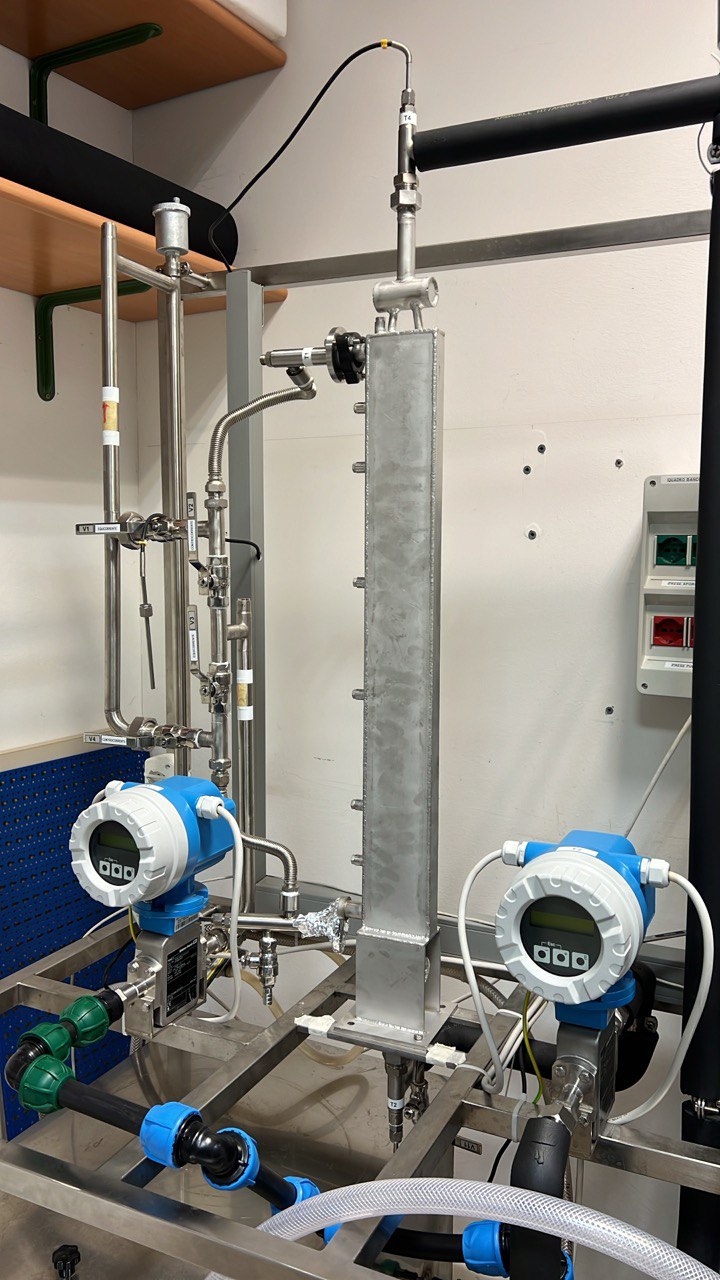
To validate the ε-NTU design method, a PPHE was designed to replicate a STHE geometry while minimizing production parameters according to laser welding process constraints, with the objective of providing a characterisation of the smallest pillow plate geometry possible. The compact design, showcased in Figure 1, ensures efficient heat transfer in a small footprint, and the design model allowed to forecast its performance beforehand. To provide more insights on the performance of Nu correlations for the OC, which are scarce in literature [10], it was decided to investigate lower Re ranges.
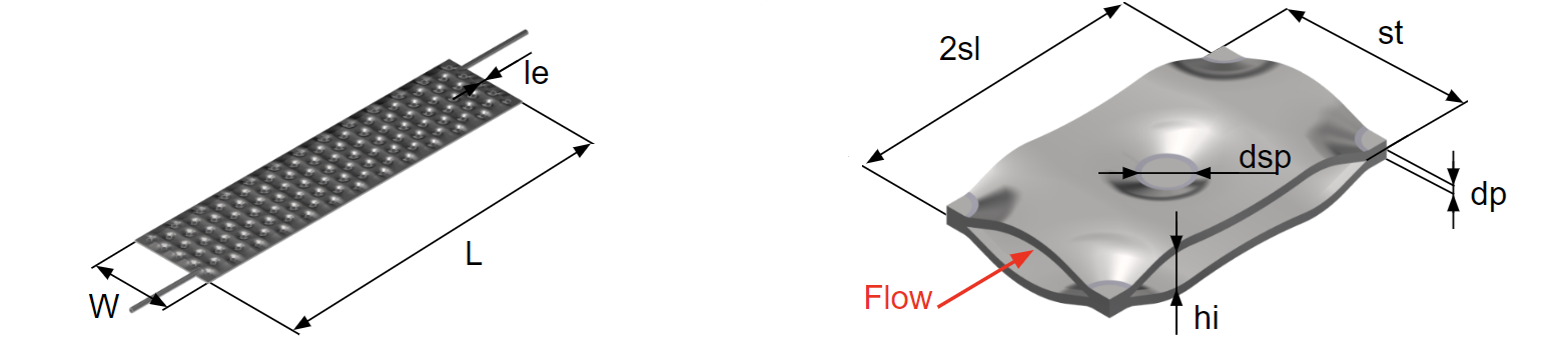
The PPHE, whose building blocks are showcase in Figure 2, features two plates, each measuring 450 mm in length (L) and 80 mm in width (W), with a thickness (dp) of 1 mm. The two-plate configuration is studied to create two ICs and three OCs. The inflated plate thickness is 5 mm (hi + 2dp), with an internal inflation of 3 mm (hi). The PPHE has two internal and three external channels, with a median surface distance between plates of 8 mm. The longitudinal pitch is 18 mm (sl), and the transversal pitch is 21 mm (st). The welded edges, not inflated, are 3 mm (le) long, and the welding spot diameter is 5 mm (dsp).
2. 3. Experimental validation set-up
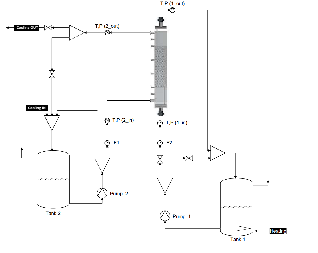
The experimental setup was designed to simulate steady-state operating conditions for the PPHE, incorporating water flow systems, temperature control and measurement, pressure measurement, and flow meters. As shown in Figure 3, the system operates using two separate fluid loops - a hot loop and a cold loop.
The hot fluid circuit (labelled as 1) begins at Tank 1, where water is heated using an electric resistance heater. Pump_1 then circulates this hot water through the PPHE. The flow rate is measured by flow meter F2, while inlet and outlet temperatures and pressures are recorded at T,P (1_in) and T,P (1_out) respectively.
Simultaneously, the cold fluid circuit (labelled as 2) starts at Tank 2. Pump_2 circulates the cold water through the PPHE. Similar to the hot loop, flow rate, inlet and outlet temperatures and pressures are measured using F1, T,P (2_in), and T,P (2_out).
The PPHE itself was designed to be equipped with multiple temperature sensors along its length, allowing for detailed temperature profiling. However, it was found that the 3mm diameter Pt100 sensors affected the fluid motion between plates and had to be avoided. After passing through the PPHE, the heated cold water is cooled using a secondary cooling system before returning to Tank 2.
This setup enables comprehensive analysis of heat transfer and hydraulic resistance characteristics of the PPHE under various operating conditions. The dual-tank system with temperature control provides thermal stability, while the extensive instrumentation allows for precise data collection. This data is invaluable for optimizing both the PPHE design and its target working conditions, as well as identifying potential improvements, which will be discussed in the conclusions section.
2. 4. Heat Transfer and Pressure Drop characterisation
To characterise the SSPPHE behaviour, two distinct thermal performance characterisation campaigns were carried out, with fixed inlet temperatures (with small variations attributable to the heat sources). The tests of the first campaign, each one referred to the identification number (ID) 1&n (n states for the test number), were performed by changing the OC flow rate within the range of 0.111-0.224 kg/s and keeping the IC flow rate constant around an averaged value of 0.111 kg/s. Conversely, the second campaign, with ID2&n, was performed by changing the IC flow rate in the range of 0.042-0.330 kg/s. The OC flow rate was set at an average value of 0.180 kg/s. As for the inlet temperature of the fluids (T1i for IC and T2i for OC), the average value was T1i=324.11K, T2i= 287.77K for the campaign ID1&n, T1i=323.77K and T2i= 285.57K for ID2&n.
Pressure drop was measured in both the inner and outer channels of the SSPPHE. However, since the pressure drop in the outer channel was unexpectedly below the sensor's accuracy (5mbar), only data for the inner channel are here reported. The pressure drop data is paired with the flow rate by timestamp, and they are processed with Equations 7-11:


To evaluate the pressure loss within the pillow plates, the pressure drop in the connections was computed using the Blasius correlation, as described in [13]. The pressure drop relationship with the flow regime is evaluated throughout the Blasius equation, that correlates the Darcy friction factor (ξ) and Re number, shown in Eq. 7. As seen in Eq. 8-9, both ξ and Re depend from the hydraulic diameter (Dh) and the velocity of the flow (v), which is calculated by dividing the volumetric flow rate by the fluid passage area (Acs). To determine Dh and Acs from the main geometrical features of the pillow plate, two different approaches from literature were selected: one from Arsenyeva et al. [14] (also referred in this text as Arsenyeva’s method), a relevant SSPPHE investigation work, and another from Piper et al. [3] (also referred in this text as Piper’s method), which is used in the design ε-NTU model to determine the internal volume (V), heat transfer area, Dh, and other relevant geometrical parameters. The mass flux rate (φ) was also computed to display pressure drop against different flow conditions and is obtained from the volumetric flow rate (Q1), the density at mean temperature (ρ) and Acs. However, since this PPHE is even smaller, a significant deviation from the available geometrical models was expected and had to be determined before analysing data from the pressure drop analysis.
2. 5. Geometrical characterisation: destructive testing and tomography.
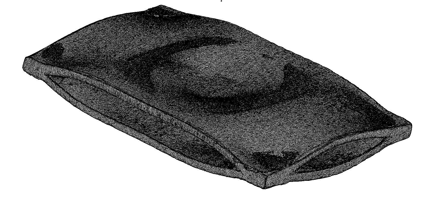
To evaluate theoretical Acs values, the pillow was cut to expose the cross-sectional area at specific points where it is at the minimum and maximum. Images were then captured with a calibrated microscope at low magnification, and a computer vision algorithm was applied to measure the area in the pictures, providing a reference range for minimum and maximum area. To validate these measurements, the inner channel was filled with distilled water, and the pillow was weighed before and after being filled, to determine the weight gain. Knowing the specific density of water at 20°C, the inner volume was computed. By dividing the volume by (L-2le), Acs can be determined, following the approach of calculating the cross-sectional area by dividing the volume element per its length (the longitudinal semi-pitch)[3]. The hydraulic diameter was determined using Eq.11, with the wet area (Areawetted) calculated by the SSPPHE design model which implements the approach from Piper et al. [3]. To better understand the characteristics of the inflated small scale pillow plates, final round of testing was performed, using a Zeiss Metrotom 1500, with a voxel size of 50-60µm. Three scans were performed: one of a cell 36*21mm, which is eight times the periodic element considered by Piper et al. [3] and two slices in the transversal direction, as seen in Figure 4 and Figure 5. This analysis could pose as an alternative method to FEM or a complementary method as an advance to classic probing. All the measurements collected for the geometrical characterisation are paramount as they allow to check the difference between the computed values, which apply to an infinitely extended pillow plate surface with negligible border effects, and the real values of the studied small scale pillow plate with the same set of geometrical parameters.
3.Results, model behaviour analysis and discussion
3. 1. Pressure drop analysis
For the characterization of the pressure drop in the Inner Channel (IC) of the Small-Scale Pillow Plate Heat Exchanger (SSPPHE), experiments were conducted over a mass flow ranging from 0.042 to 0.330 kg/s. The temperature in the IC was intended to be constant, but minor variations due to system instabilities resulted in a mean temperature range of 313.15-320.15 K. The Outer Channel (OC) maintained a temperature range of 288.15-290.15 K.
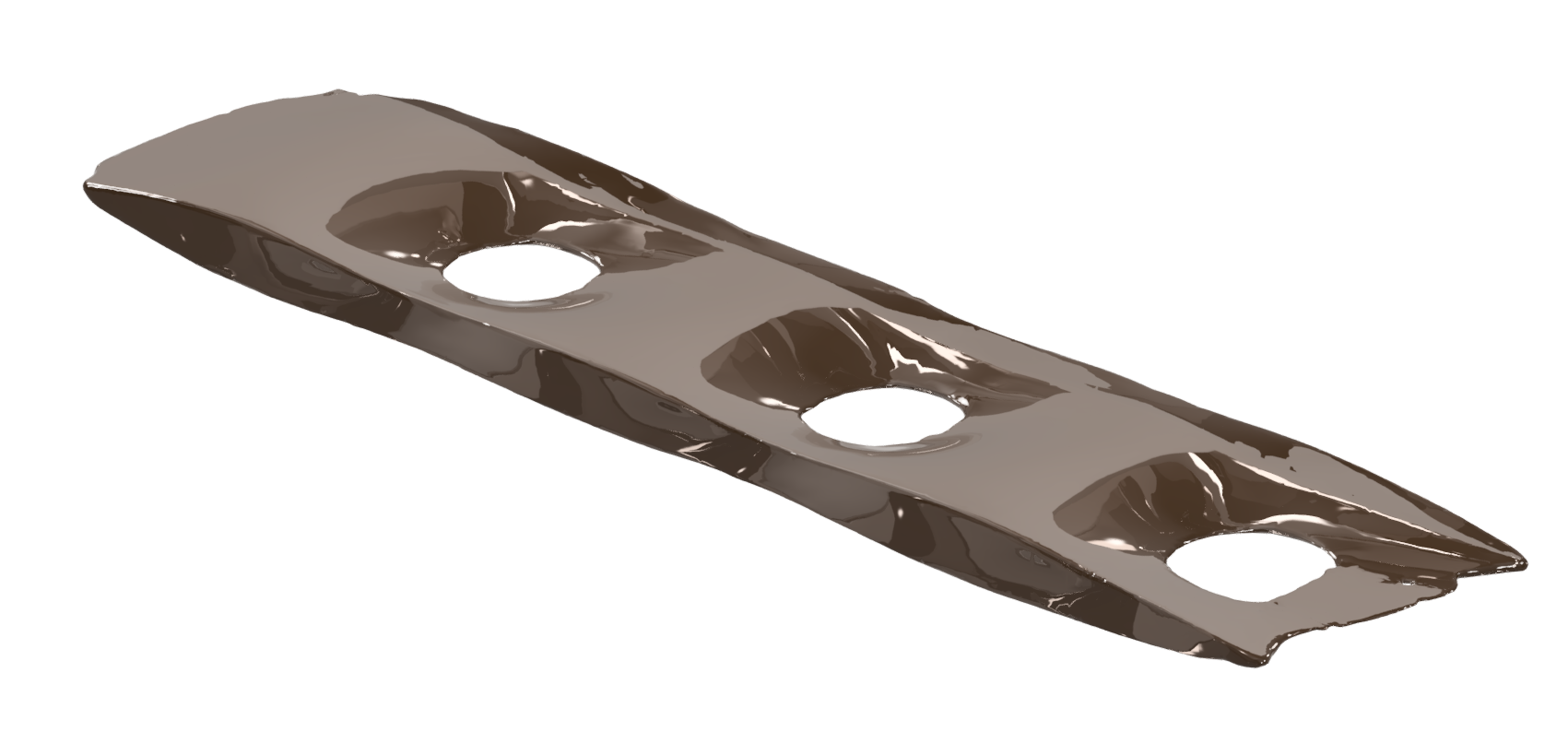
Both in the Darcy friction factor, and Reynolds number calculation, there is a dependency from the hydraulic diameter and the velocity. Thus, these results strongly depend on the geometrical modelling for the design phase, and on the geometrical measurements in the experimental results analysis. The value for the average passage area obtained from the measured volume of contained water by the pillow plate length, is 118.36 mm² (water density at 20°C was considered 998.29 kg/m3). This value is validated against the range defined by the minimum and maximum values of the area measured from the images, which are 77.60 mm² and 148.60 mm² and represents an easy quantity to determine in an industrial production setting. From the cross sectional cut images, hi was found to have a maximum and a minimum of 2.99 mm and 2.52 mm: while the former value indicates a good agreement with the nominal hi value derived by the geometrical modelling in the design model, we conclude that there are also local deviations from it. The Dh values obtained with geometrical models were 4.24 mm (Arsenyeva’s method), 4.06 mm (Piper’s method), while 3.32 mm was calculated from the destructive testing (later referred to as “experimental parameters”). The tomography on the periodic element and the plate slice helped confirm these results. Using nTopology as a mesh analysis software to input the values of Volume and wet Area in Eq.11, Dh equals to 4.07mm, which confirms the approach by Piper et al. However, it is possible to see from the volume render in Figure 5, that not only the lateral borders have a distinctly different inflation than the periodic elements, but also that the inflation might be uneven. Moreover, it should be noted that the following slice, would be shifted on the transversal direction by a transversal pitch length, meaning that the recirculation zones alternate, generating parasitic pressure loss. Using the pressure drop data and the determined cross-sectional areas and hydraulic diameters, the Reynolds number, mass flux, and Darcy factor were computed. Figure 6a illustrates the relationship between the pressure drop in the IC and mass flux, while Figure 6b presents the computed Darcy factor for the three different approaches. Based on the measured points, three different fitting curves were computed using Eq. 7. The resulting curves are shown in Figure 7, with the coefficients of Eq. 7 found to be: 𝑛1=4.778 (blue line – geometry calculated with Arsenyeva’s method), n1=3.922 (orange line – Piper’s method), and 𝑛1=2.135 (green line – experimental parameters), while 𝑛2=−0.116 for all curves.
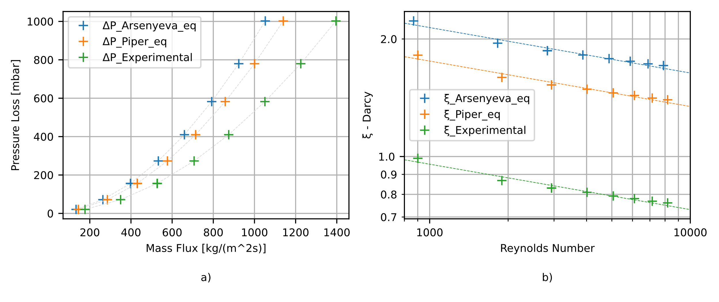
Before commenting the results shown in Figures 6 and 7, it is worth noting that they are significantly influenced by how pressure drop data is processed with the computed areas and hydraulic diameter, which underscores the importance of accurate measurements and geometrical modelling. Here, an underestimation from the model of the real passage area, could result in a great underestimation of the real pressure drop. Conversely, the measured pressure drop will lead to a wrong determination of the values for Eq. 7 unless accurate geometrical measurement is performed. In Figure 6 this concept can be seen and understood. While Figure 6a shows the pressure drop in the IC plotted against mass flux, Figure 6b shows the computed Darcy factor against Reynolds number. Figure 6a indicates higher mass flux numbers for the lower computed area at a given pressure drop value (left blue markers-Arsenyeva vs right green markers-experimental), while Figure 6b suggests that the actual passage area and hydraulic diameter are significantly lower than those calculated by the geometrical correlations. In fact, the curves in Figure 6b calculated with Piper and Arsenyeva methods, are, at a given Reynolds number, too high compared to all available pressure drop data on PPHEs [10].
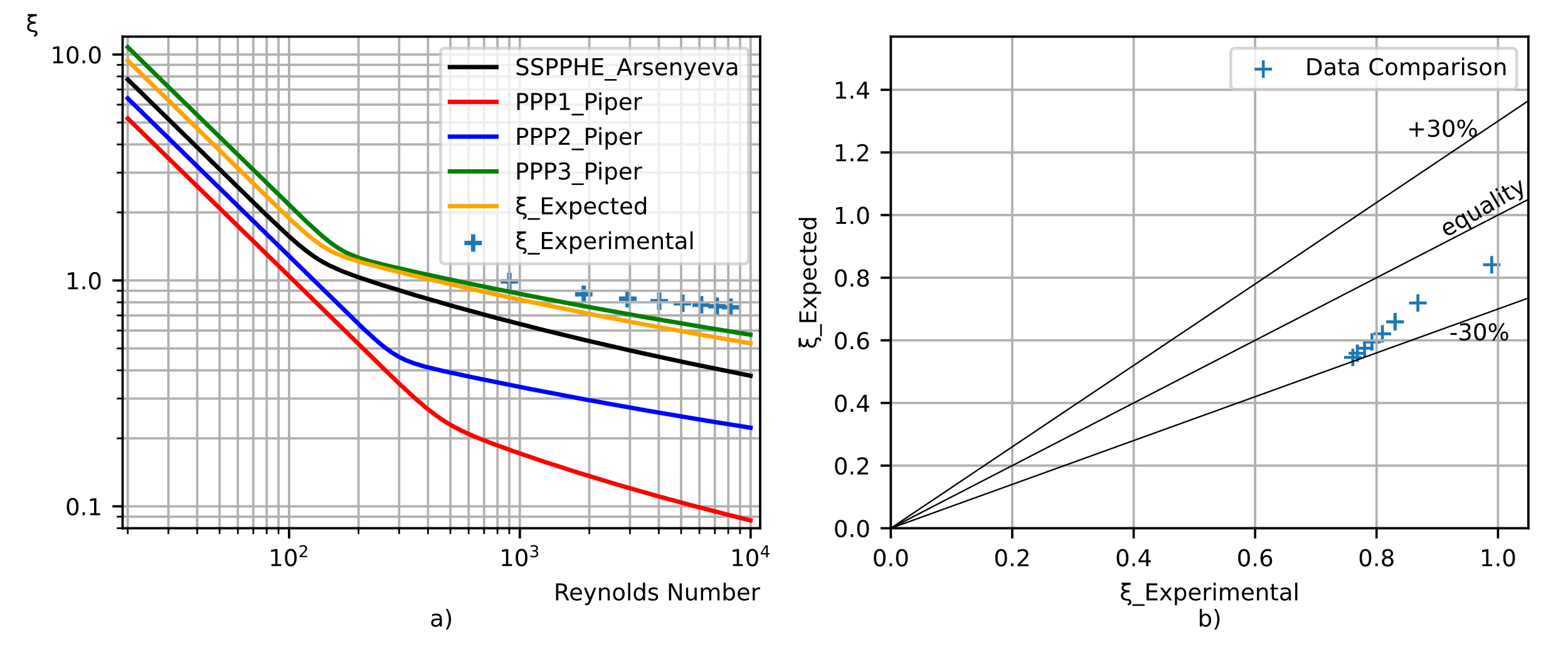
The experimental results are compared with data from literature by plotting the computed Darcy factor using Eq. 8 against the analytical results derived from the method used by Arsenyeva et al. in [8]: Figure 7a shows four curves derived in [14] for significant PPHE geometries in literature, and an orange curve representing the correlation presented in [14] but calculated for the SSPPHE in this study. This is the curve that the measured data is expected to fit. The blue cross marks on the plot represent the experimental Darcy values, derived from pressure measurements and the average area and hydraulic diameter obtained from experimental destructive testing explained in section 2.5. Figure 7b provides a direct comparison between these experimental Darcy values, “ξ_Experimental”, and those computed by our implementation of the geometrical model, “ξ_Expected”. The latter values are obtained using the method from [14] with the pillow plate parameters from this study, at the same Reynolds numbers. This plot shows a deviation of up to 30% from equality, which can be attributed to the border effect not considered by current geometrical models [3], [14], and the averaging technique used in this study, which does not account for the flow regime near the narrowly inflated borders of the internal channel of the SSPPHE. From the tomography volume meshes, we were able to see that the central portion of the Small-Scale Pillow Plates inflated normally reaching a conformation very close to the ideal geometry used in the approaches from literature. However, cross sectional cuts, showed a distinctly different geometry in the border areas, and the tomography analysis confirmed the presence of many underinflated alternating areas, which result in a less than modelled effective cross-sectional area. This effectively explains the thorough underestimation of the Darcy friction factor shown in Figure 7b.
3.2. Heat transfer analysis and design validation
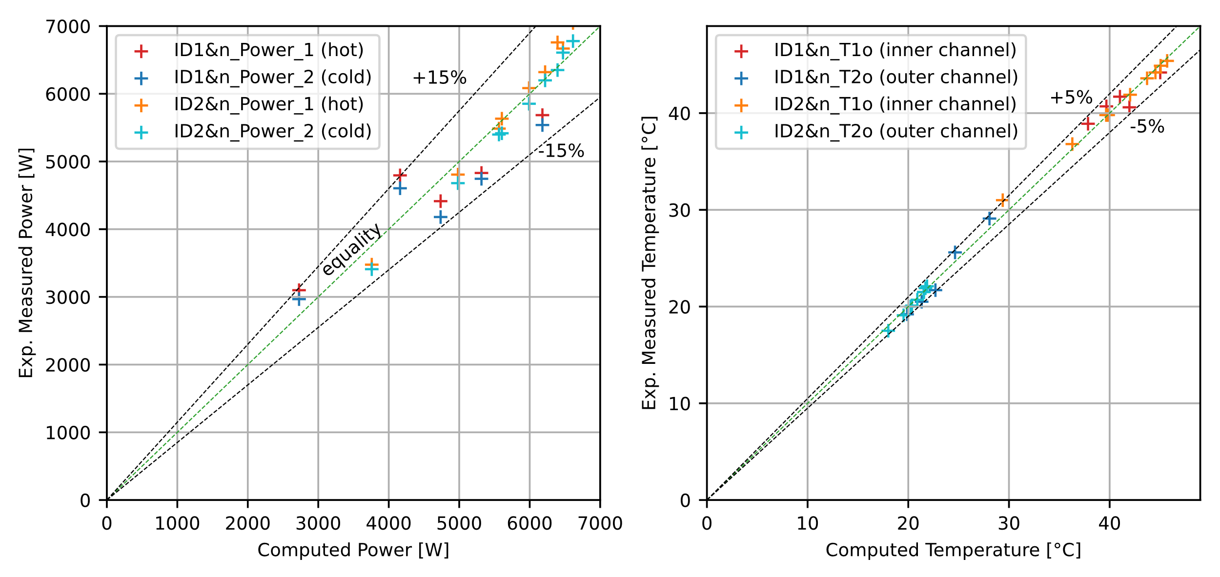
The data set presented by Table 1 reveals critical insights into the behaviour of the heat exchanger across two experimental campaigns. In the first campaign, the IC conditions were kept constant, and the OC Reynolds numbers (Re2) are varied (524 to 1807), leading to a wide range in the thermal resistance of the OC. In the second campaign, Reynolds number is varied only in the internal channel. The moderate deviation between experimental and calculated overall heat transfer coefficient values reported in Table 1, suggest the onset of turbulence at low Reynolds number for both the OC and IC of the SSPPHE. It is generally possible, across the dataset, to appreciate the general fidelity of the predictions of the model, but also some variability in the stability of the experimental system, since the non-adiabaticity (%NA) does not seem to correlate to the flow regime and thermophysical property variation. In Figure 8, two relevant output values predicted by the ε-NTU model are plotted against the measured values of two key output parameters of the SSPPHE: the thermal power, and the outlet temperature for both the inner and outer channel. The comparison of computed vs. measured output powers, as depicted in Figure 8a, provides critical insights into the performance and accuracy of the ε-NTU model for the PPHE. The ε-NTU model demonstrates accuracy within specified Reynolds (Re) and Prandtl (Pr) number ranges but exhibits higher deviations when applied increasingly outside these ranges, particularly in the OC. In Figure 8a it is also possible to see separate points for IC (hot fluid) and OC (cold fluid), with the gap related to the non-adiabaticity (NA). Positive deviations indicate underestimation of a computed parameter.
Table 1: Summary of key parameters of influence for performance evaluation: effectiveness (ε), global heat exchange coefficient (U), Non-adiabaticity (NA), Reynolds (Re) and Prandtl (Pr) numbers calculated by the presented ε-NTU model, heat exchange coefficients (h) calculated by the model, Power (P). The subscript “exp” is for values calculated from experimental data, “comp” is for parameters computed by the model, while 1 and 2 indicate the inner (hot) and outer (cold) channel.
|
ID |
εexp (%) |
εcomp (%) |
Uexp (W/m2K) |
NA (%) |
Re1 |
Re2 |
Pr1 |
Pr2 |
h1 (W/m2K) |
h2 (W/m2K) |
Ucomp (W/m2K) |
Pcomp (W) |
|
1&1 |
36.78 |
33.81 |
919 |
4.25 |
2649 |
524 |
3.73 |
6.51 |
814 |
936 |
814 |
2727 |
|
1&2 |
28.13 |
25.41 |
1410 |
3.97 |
2657 |
1000 |
3.87 |
6.88 |
1218 |
1537 |
1218 |
4160 |
|
1&3 |
23.93 |
27.12 |
1132 |
5.31 |
2737 |
1121 |
3.82 |
7.42 |
1321 |
1703 |
1321 |
4736 |
|
1&4 |
26.86 |
30.09 |
1270 |
1.78 |
2705 |
1351 |
3.86 |
7.62 |
1471 |
1970 |
1471 |
5316 |
|
1&5 |
31.09 |
34.7 |
1492 |
2.57 |
2663 |
1807 |
3.93 |
7.8 |
1718 |
2460 |
1718 |
6180 |
|
2&1 |
50.83 |
56.04 |
1039 |
1.92 |
914 |
1269 |
4.26 |
8.09 |
4056 |
1909 |
1204 |
3759 |
|
2&2 |
35.34 |
37.61 |
1292 |
2.63 |
1904 |
1327 |
4.02 |
7.91 |
6794 |
1962 |
1399 |
4982 |
|
2&3 |
27.19 |
28.13 |
1440 |
3.82 |
2947 |
1354 |
3.91 |
7.8 |
9249 |
1984 |
1495 |
5605 |
|
2&4 |
27.19 |
28.02 |
1437 |
1.59 |
2945 |
1346 |
3.92 |
7.82 |
9252 |
1977 |
1491 |
5564 |
|
2&5 |
21.91 |
22.42 |
1515 |
3.8 |
4026 |
1368 |
3.83 |
7.73 |
11528 |
1995 |
1552 |
5991 |
|
2&6 |
23.24 |
23.31 |
1578 |
1.93 |
5071 |
1368 |
3.76 |
7.62 |
13552 |
1989 |
1581 |
6219 |
|
2&7 |
23.76 |
23.93 |
1602 |
6.04 |
6112 |
1368 |
3.74 |
7.64 |
15502 |
1990 |
1606 |
6395 |
|
2&8 |
25 |
24.49 |
1668 |
0.9 |
7150 |
1370 |
3.73 |
7.6 |
17354 |
1990 |
1624 |
6472 |
|
2&9 |
25.46 |
24.84 |
1701 |
3.8 |
8190 |
1380 |
3.71 |
7.57 |
19118 |
1999 |
1645 |
6614 |
IDs 1&1 and 1&2 show significant positive deviations (13.65%, 15.26%) with Pr2 values that are close to the lower limit valid range. High deviations are also observed in the second experimental run for IDs 2&9 (6.53%) and 2&7 (5.68%), indicating underestimation at higher Reynolds numbers in the inner channel.
Negative Deviations indicate overestimation by the model, and IDs 1&3, 1&4, and 1&5 exhibit negative deviations (-6.80%, -9.13%, -8.01%) despite being within the valid range for Re1, most likely due to error from OC low Re conditions. ID 2&1 (Re1 = 914) shows a -7.53% deviation: since the Reynolds value for the IC is below the valid range of the Nusselt correlation, it is possible to confirm reduced accuracy outside the specified ranges. In Figure 8b, deviation in the prediction of outlet temperatures is shown, completing the information from Figure 8a. The deviations are much smaller for the predicted outlet Temperatures, which is to be expected since both the computed power and the measured power are derived from the Temperature differences, the specific heat, and the measured flow rates. Given that the highest thermal resistance is in the outer channel, it can be stated that the overall thermal resistance is closer to its value. However, the model's predictions are reliable within a 15% deviation, allowing the outer channel correlation to be used down to Re = 1000, thereby extending its applicability. This extension is significant for designing heat exchangers operating under varied flow conditions, ensuring robust thermal performance predictions.
4. Conclusions
This study provides valuable insights into the design, characterization, and performance of small-scale pillow plate heat exchangers (SSPPHEs). The effectiveness-NTU (ε-NTU) model developed for SSPPHEs demonstrated good agreement with experimental data, with thermal power and efficiency predictions generally within ±15% of measured values, validating the applicability of the ε-NTU method for compact PPHE designs. The study successfully extended the applicability of existing heat transfer correlations to lower Reynolds numbers (down to Re = 1000) for the outer channel, broadening the operational range for SSPPHE designs.
Pressure drop characterization revealed that experimental Darcy factor values showed deviations of up to 30% from theoretical predictions, highlighting the significant impact of border effects in compact designs not accounted for in current geometrical models. The combination of destructive testing and tomography provided crucial insights into the actual geometry of SSPPHEs, revealing local deviations from nominal dimensions and uneven inflation patterns, which is vital for refining future geometrical models. In light of this consideration, future work could explore the application of advanced modelling techniques, such as the FEM-based simulation and novel geometric parameters proposed by Sabourishirazi et al. [6], to further refine the design and performance prediction of SSPPHEs. An important observation is left to be made for future works aiming to characterise the outer channel pressure drop: since the accuracy and maximum allowable pressure are bound by physical constraint by the strength and stiffness of the membrane of the pressure sensor, it is important to design the testing set-up accordingly, to allow less resistant and more accurate sensors to be employed.
The moderate deviation between experimental and calculated overall heat transfer coefficients suggests the onset of turbulence at lower Reynolds numbers than expected for both inner and outer channels of the SSPPHE. However, it is to be investigated the effect of border effects on the heat transfer data processing. Since there are suspects of unforeseen recirculation, it is reasonable to expect zones with higher local Reynolds number. Notably, the developed SSPPHE achieved a high heat transfer area to volume ratio of 340 m²/m³, demonstrating the potential for highly compact and efficient heat exchanger designs.
Looking ahead, several key areas warrant further investigation to advance SSPPHE technology. Primarily, there is a need for refined geometrical modelling that accounts for border effects and local deviations in inflation patterns, particularly for small-scale designs.
Extending the operational range studies is crucial to validate and potentially expand the applicability of heat transfer and pressure drop correlations across a wider range of Reynolds and Prandtl numbers, especially in the transitional flow regime [10]. This would enhance the robustness of design methodologies for SSPPHEs across various operating conditions.
Aknowledgements
This research was made possible through the collaborative efforts of precious individuals and organizations. We extend our appreciation to DavCoil srl for their support in constructing the SSPPHE prototype and providing instrumentation crucial for our experimental work.
We are particularly grateful to Dr. Mauro Hueller, Dr. Francesco Negrisolo, and Dr. Raffaele De Biasi for their exceptional assistance throughout the experimental phase. Their expertise, dedication, and insightful contributions have greatly enhanced the quality and depth of our research.
References
[1] R. Eldeeb, J. Ling, V. C. Aute, and R. Radermacher, 'Heat Transfer Enhancement Using Approximation Assisted Optimization for Pillow Plate Heat Exchangers', 2018.
View Article
[2] J. Mitrovic and B. Maletic, 'Numerical Simulation of Fluid Flow and Heat Transfer in Thermoplates', Chemical Engineering & Technology, vol. 34, no. 9, pp. 1439-1448, 2011, doi: https://doi.org/10.1002/ceat.201100271.
View Article
[3] M. Piper, A. Olenberg, J. M. Tran, and E. Y. Kenig, 'Determination of the geometric design parameters of pillow-plate heat exchangers', Applied Thermal Engineering, vol. 91, pp. 1168-1175, Dec. 2015, doi: 10.1016/j.applthermaleng.2015.08.097.
View Article
[4] R. Afsahnoudeh, A. Wortmeier, M. Holzmüller, Y. Gong, W. Homberg, and E. Y. Kenig, 'Thermo-Hydraulic Performance of Pillow-Plate Heat Exchangers with Secondary Structuring: A Numerical Analysis', Energies, vol. 16, no. 21, Art. no. 21, Jan. 2023, doi: 10.3390/en16217284.
View Article
[5] A. Sabourishirazi, M. Ghodrat, J.-L. Liow, and M. Behnia, 'Recent advances in design and performance optimization of pillow-plate heat exchangers: a critical review', J Therm Anal Calorim, vol. 148, no. 24, pp. 13679-13707, Dec. 2023, doi: 10.1007/s10973-023-12571-w.
View Article
[6] A. Sabourishirazi, J.-L. Liow, and M. Ghodrat, 'A thorough investigation of geometric and thermohydraulic features in pillow-plate heat exchangers', Applied Thermal Engineering, vol. 254, 2024, doi: 10.1016/j.applthermaleng.2024.123906.
View Article
[7] M. Piper, A. Zibart, and E. Y. Kenig, 'New design equations for turbulent forced convection heat transfer and pressure loss in pillow-plate channels', International Journal of Thermal Sciences, vol. 120, pp. 459-468, Oct. 2017, doi: 10.1016/j.ijthermalsci.2017.06.012.
View Article
[8] O. Arsenyeva, J. Tran, M. Piper, and E. Kenig, 'An approach for pillow plate heat exchangers design for single-phase applications', Applied Thermal Engineering, vol. 147, pp. 579-591, Jan. 2019, doi: 10.1016/j.applthermaleng.2018.08.083.
View Article
[9] I. H. Bell, J. Wronski, S. Quoilin, and V. Lemort, 'Pure and Pseudo-pure Fluid Thermophysical Property Evaluation and the Open-Source Thermophysical Property Library CoolProp', Ind. Eng. Chem. Res., vol. 53, no. 6, pp. 2498-2508, Feb. 2014, doi: 10.1021/ie4033999.
View Article
[10] M. Mastani Joybari, H. Selvnes, A. Sevault, and A. Hafner, 'Potentials and challenges for pillow-plate heat exchangers: State-of-the-art review', Applied Thermal Engineering, vol. 214, p. 118739, Sep. 2022, doi: 10.1016/j.applthermaleng.2022.118739.
View Article
[11] D. P. Sekulic', R. K. Shah, and A. Pignotti, 'A Review of Solution Methods for Determining Effectiveness-NTU Relationships for Heat Exchangers With Complex Flow Arrangements', Applied Mechanics Reviews, vol. 52, no. 3, pp. 97-117, Mar. 1999, doi: 10.1115/1.3098928.
View Article
[12] R. Sukarno, N. Putra, I. I. Hakim, F. F. Rachman, and T. M. I. Mahlia, 'Multi-stage heat-pipe heat exchanger for improving energy efficiency of the HVAC system in a hospital operating room1', International Journal of Low-Carbon Technologies, vol. 16, no. 2, pp. 259-267, May 2021, doi: 10.1093/ijlct/ctaa048.
View Article
[13] A. Celen, A. S. Dalkilic, and S. Wongwises, 'Experimental analysis of the single phase pressure drop characteristics of smooth and microfin tubes', International Communications in Heat and Mass Transfer, vol. 46, pp. 58-66, Aug. 2013, doi: 10.1016/j.icheatmasstransfer.2013.05.010.
View Article
[14] O. Arsenyeva, M. Piper, A. Zibart, A. Olenberg, and E. Y. Kenig, 'Investigation of heat transfer and hydraulic resistance in small-scale pillow-plate heat exchangers', Energy, vol. 181, pp. 1213-1224, Aug. 2019, doi: 10.1016/j.energy.2019.05.099.
View Article
[1] R. Eldeeb, J. Ling, V. C. Aute, and R. Radermacher, 'Heat Transfer Enhancement Using Approximation Assisted Optimization for Pillow Plate Heat Exchangers', 2018. View Article
[2] J. Mitrovic and B. Maletic, 'Numerical Simulation of Fluid Flow and Heat Transfer in Thermoplates', Chemical Engineering & Technology, vol. 34, no. 9, pp. 1439-1448, 2011, doi: https://doi.org/10.1002/ceat.201100271. View Article
[3] M. Piper, A. Olenberg, J. M. Tran, and E. Y. Kenig, 'Determination of the geometric design parameters of pillow-plate heat exchangers', Applied Thermal Engineering, vol. 91, pp. 1168-1175, Dec. 2015, doi: 10.1016/j.applthermaleng.2015.08.097. View Article
[4] R. Afsahnoudeh, A. Wortmeier, M. Holzmüller, Y. Gong, W. Homberg, and E. Y. Kenig, 'Thermo-Hydraulic Performance of Pillow-Plate Heat Exchangers with Secondary Structuring: A Numerical Analysis', Energies, vol. 16, no. 21, Art. no. 21, Jan. 2023, doi: 10.3390/en16217284. View Article
[5] A. Sabourishirazi, M. Ghodrat, J.-L. Liow, and M. Behnia, 'Recent advances in design and performance optimization of pillow-plate heat exchangers: a critical review', J Therm Anal Calorim, vol. 148, no. 24, pp. 13679-13707, Dec. 2023, doi: 10.1007/s10973-023-12571-w. View Article
[6] A. Sabourishirazi, J.-L. Liow, and M. Ghodrat, 'A thorough investigation of geometric and thermohydraulic features in pillow-plate heat exchangers', Applied Thermal Engineering, vol. 254, 2024, doi: 10.1016/j.applthermaleng.2024.123906. View Article
[7] M. Piper, A. Zibart, and E. Y. Kenig, 'New design equations for turbulent forced convection heat transfer and pressure loss in pillow-plate channels', International Journal of Thermal Sciences, vol. 120, pp. 459-468, Oct. 2017, doi: 10.1016/j.ijthermalsci.2017.06.012. View Article
[8] O. Arsenyeva, J. Tran, M. Piper, and E. Kenig, 'An approach for pillow plate heat exchangers design for single-phase applications', Applied Thermal Engineering, vol. 147, pp. 579-591, Jan. 2019, doi: 10.1016/j.applthermaleng.2018.08.083. View Article
[9] I. H. Bell, J. Wronski, S. Quoilin, and V. Lemort, 'Pure and Pseudo-pure Fluid Thermophysical Property Evaluation and the Open-Source Thermophysical Property Library CoolProp', Ind. Eng. Chem. Res., vol. 53, no. 6, pp. 2498-2508, Feb. 2014, doi: 10.1021/ie4033999. View Article
[10] M. Mastani Joybari, H. Selvnes, A. Sevault, and A. Hafner, 'Potentials and challenges for pillow-plate heat exchangers: State-of-the-art review', Applied Thermal Engineering, vol. 214, p. 118739, Sep. 2022, doi: 10.1016/j.applthermaleng.2022.118739. View Article
[11] D. P. Sekulic', R. K. Shah, and A. Pignotti, 'A Review of Solution Methods for Determining Effectiveness-NTU Relationships for Heat Exchangers With Complex Flow Arrangements', Applied Mechanics Reviews, vol. 52, no. 3, pp. 97-117, Mar. 1999, doi: 10.1115/1.3098928. View Article
[12] R. Sukarno, N. Putra, I. I. Hakim, F. F. Rachman, and T. M. I. Mahlia, 'Multi-stage heat-pipe heat exchanger for improving energy efficiency of the HVAC system in a hospital operating room1', International Journal of Low-Carbon Technologies, vol. 16, no. 2, pp. 259-267, May 2021, doi: 10.1093/ijlct/ctaa048. View Article
[13] A. Celen, A. S. Dalkilic, and S. Wongwises, 'Experimental analysis of the single phase pressure drop characteristics of smooth and microfin tubes', International Communications in Heat and Mass Transfer, vol. 46, pp. 58-66, Aug. 2013, doi: 10.1016/j.icheatmasstransfer.2013.05.010. View Article
[14] O. Arsenyeva, M. Piper, A. Zibart, A. Olenberg, and E. Y. Kenig, 'Investigation of heat transfer and hydraulic resistance in small-scale pillow-plate heat exchangers', Energy, vol. 181, pp. 1213-1224, Aug. 2019, doi: 10.1016/j.energy.2019.05.099. View Article