Journal of Fluid Flow, Heat and Mass Transfer (JFFHMT)
ISSN: 2368-6111

Volume 11 - Year 2024 - Pages 240-247
DOI: 10.11159/jffhmt.2024.024
Terminal Settling Velocity of Cylindrical Rods of Various Shapes
Amirhossein Hamidi1, Daniel Daramsing1, Mark D. Gordon2, Liisa M. Jantunen3, Ronald E. Hanson1
1York University, Department of Mechanical Engineering
4700 Keele St, Toronto, Ontario, Canada M3J1P0
ahamidi7@yorku.ca; danielvd@my.yorku.ca; hansonre@yorku.ca
2York University, Earth and Space Science and Engineering
4700 Keele St, Toronto, Ontario, Canada M3J1P0
mgordon@yorku.ca
3Environment and Climate Change Canada, Air Quality Processes Research Section
6248 8th Line, Egbert, Ontario, Canada L0L1N0
Liisa.Jantunen@ec.gc.ca;
Abstract - In this research, a set of straight, curved, V-shaped, and U-shaped cylindrical rods are dropped in a chamber filled with a quiescent glycerin mixture to approximate the settling of microplastic fibres in the environment. The fall trajectory and terminal velocity of the rods are determined using cameras facing the two perpendicular sides of the chamber. The results show that the terminal velocities of the curved and V-shaped rods are greater than those of the straight rods with the same diameter and aspect ratio. U-shaped rods always exhibit a greater terminal velocity than straight rods with the same dimensions. As the aspect ratio of a U-shaped rod increases, the terminal velocity initially increases, reaches a peak value, and then decreases, reflecting the interplay between the length of the rod arms and the inclination angle. This research shows that fibre shape significantly affects the terminal velocity, which must, therefore, be included in future non-dimensional models to accurately predict the transport of microfibres in the environment.
Keywords: Microplastics; Microfibres; Settling Velocity; Particle; Environment.
© Copyright 2024 Authors - This is an Open Access article published under the Creative Commons Attribution License terms. Unrestricted use, distribution, and reproduction in any medium are permitted, provided the original work is properly cited.
Date Received: 2023-12-07
Date Revised: 2024-07-12
Date Accepted: 2024-07-28
Date Published: 2024-08-16
1. Introduction
Microplastics (MPs) are a subset of plastics with sizes ranging between 1 µm and 5 mm [1-3]. MP pollution is known to spread through the environment, span the globe from urban to remote areas [4-7], and pose risks to human health and ecosystems. For instance, inhaling MPs can lead to respiratory illnesses [8-10]. These particles may also contain components and additives which can harm human health when inhaled or ingested [11, 12]. Their presence in ecosystems raises concerns about food safety and potential health issues [13]. Furthermore, MPs in Arctic glaciers can absorb sunlight, reducing the ice surface albedo and accelerating ice melting [14, 15]. Of reported atmospheric deposition samples, fibres are a prevalent shape, and often the most abundant [2, 5, 16, 17]. Past efforts to model the atmospheric transport of microplastic fibres (MFs) have usually relied on simplified representations of shapes such as spheres or a single straight fibre to estimate properties such as terminal velocity [6, 18, 19]. In the present research, the settling of rigid cylindrical rods of various finite lengths and shapes is studied to better understand how size and shape can affect the terminal velocity of microfibres. This is important in atmospheric transport studies, such as that of Ward et al. [20], where transport predictions of microplastics are sensitive to the size and shape of the particles modelled as equivalent spheres.
Numerous aerodynamic models to estimate the terminal velocity of general non-spherical particles were reviewed by Michaelides and Feng [21]. At the core of modelling predictions is the particle size or shape representation. For example, Ganser [22] modelled the drag coefficient of isometric and nonisometric particles using a generalized Reynolds number, a function of Stoke’s and Newton’s shape factors, to predict the drag coefficient. In the study conducted by Song et al. [23], drop tests were performed using spheres, cubes, and cylinders of varying sizes and aspect ratios in glycerin mixtures with different viscosities. They introduced sphericity, indicating the ratio of the area of a volume-equivalent sphere to the particle area, and projected area ratio, indicating the ratio of the projected area of a volume-equivalent sphere to the particle projected area, to model their results. Bagheri and Bonadonna [24] conducted experiments in a vertical wind tunnel to determine the terminal velocity of a wide range of non-spherical particles. They modelled the drag coefficient of irregular particles utilizing the shape factors of flatness (the ratio of shortest length to intermediate length) and elongation (the ratio of intermediate to longest length). Zhang and Choi [25] modelled the terminal velocity of microplastic particles with the ability to differentiate between various shapes, including fibres, films, and fragments. Henn [26] proposed a theoretical correlation for the settling velocity of long cylindrical particles. When comparing the ratio of the aerodynamic equivalent diameter to the fibre diameter (given by Da/DC) with the experimental findings, their model exhibits a maximum discrepancy of 6% for glass fibre with aspect ratios between 5 and 150. Khalili and Liu [27] introduced an approach to estimating the drag coefficient of an infinite cylinder through the numerical analysis of the flow around the cylinder. Huner and Hussey [28] developed a drag coefficient model for an infinite circular cylinder within a Reynolds number range of 0.23 to 2.6, while Sen et al. [29] studied a uniform flow past a cylinder and provided a drag coefficient model applicable to Reynolds numbers between 6 and 40. However, when applied strictly to finite fibres of various shapes, these models all provide significantly varying results, and these results vary with Reynolds number. The recent work of the present authors provides a semi-empirical model to estimate the terminal velocity of both straight and curved cylindrical rods at Reynolds numbers applicable to microfibres in the atmosphere [30]. However, microfibres can take on a wider range of shapes.
Atmospheric deposition samples show that microplastic fibre shapes vary [2, 16, 31, 32], highlighting the question of geometry effects on settling behaviour. Concerning curvature, Rong et al. [33] found that curved fibres with a lower radius of curvature reach a faster terminal velocity terminal and achieve it more quickly with little overshoot compared to fibres with a larger radius of curvature. Yang et al. [34] also observed that curved fibres settle faster in their experiments. Nguyen et al. [35] found that larger curliness in fibre geometry leads to a lower terminal velocity, especially for fibres longer than 1 mm. Marchetti et al. [36] investigated the deformation of elastic fibres as they reach their terminal velocity. Their findings indicate that fibres may adopt a V shape under some conditions, while larger fibres can take on a U shape. Geometry or mass distribution asymmetry can also affect fibre orientation and terminal velocity. Roy et al. [37] demonstrated that fibres with an asymmetric distribution of radius or mass density experience a transition from a vertical to an oblique orientation as the Archimedes number increases or the degree of asymmetry decreases. A dumbbell-shaped particle of two spheres connected by a weightless rod, studied by Candelier et al. [39], settles vertically when the spheres vary significantly with the larger at a lower position. However, as the size difference reduces, the orientation becomes oblique and horizontal when symmetric. Angle et al. [38] demonstrated that a cylinder with non-uniform mass distribution settles vertically at AR = 1 and slightly oblique at AR = 2 and 4. Where the cylinders adopted oblique orientations, they exhibited horizontal drift.
Many models that relate drag coefficients and Reynolds numbers for non-spherical geometries falling in air or liquid cannot accurately predict the terminal velocity of single straight fibres. Additionally, the effect of the shape of individual cylindrical rods on their terminal velocity at low Reynolds numbers is not yet extensively studied. In the present study, an experimental investigation is used to determine and compare the terminal velocities of cylindrical rods with four different geometries: straight, curved, V-shaped, and U-shaped. Our research aims to provide a deeper understanding of how various geometries affect the terminal velocity of microplastic fibres settling in the atmosphere. In this paper, Section 2 describes the experimental methods, test specimens, and equipment. Results on the terminal velocity are included in Section 3, followed by conclusions in Section 4.
2. Materials and Methods
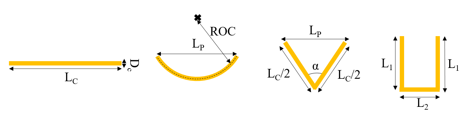
The Reynolds number range (based on the diameter of a volume-equivalent sphere) associated with the microfibres settling in the atmosphere was predicted using the microfibre dimensions reported in the literature [5, 39-42] and the Henn model [26]. The calculations suggest that the Reynolds number is smaller than 5. Glycerin-water mixture with viscosities up to 1000 times as large as that of water enables us to use millimeter-scale metallic rods having Reynolds numbers less than 5 and makes it feasible to track the 3D fall trajectory and orientation of cylindrical rods. The straight, curved, V-shaped, and U-shaped cylindrical rods investigated in this research are all made of brass with a density of 8730±49 kg/m3 and have diameters (DC) of 0.50, 0.81, and 1.0 mm (with an uncertainty of ±0.05 mm) and aspect ratios (AR) varying from 10 to 120. The rods were cut with the mentioned aspect ratios with a tolerance of 0.1 mm. A schematic of the studied rods is shown in Figure 1. The radius of curvature (ROC) of the curved rods ranges from 19.90 mm to 36.40 mm, the bend angle (α) of the V-shaped rods varies between 45 and 135 degrees, and the length ratio of the middle arm (L2) to the side arm (L1) for the U-shaped rods is 1. The degree of curvature and bend for the curved and V-shaped rods respectively is denoted as C and defined as
where LP is the projected length of the curved and V-shaped rods (shown in Figure 1) and LC is the total length of the rod. Table 1 shows the dimensions of the rod geometries used in this study.
The experiments are performed in a setup similar to that of Hamidi et al. [30]. Briefly described herein, two monochromatic cameras (Iron CXP 250) are positioned to face two perpendicular sides of the chamber, capturing the trajectory and orientation of cylindrical rods as they fall within the quiescent glycerin-water chamber. A third camera, under the tank, is used to observe the rotation of the falling rods. Rods are illuminated by two 10-watt LED lights with acrylic diffuser plates placed behind the chamber. The chamber is filled with a mixture of 90% glycerine and 10% water.
Table 1: The rod geometries studied in this research (Dc is the rod diameter, AR is the rod aspect ratio, ROC is the radius of curvature for curved rods, and α is the bend angle for V-shaped rods).
|
Geometry |
DC (mm) |
AR |
ROC (mm) |
α (degrees) |
|
Straight |
0.50 |
10, 20, 30, 60, 90, 120 |
|
|
|
0.81 |
10, 20, 30, 40, 50, 60, 70, 90. |
|
|
|
|
1.00 |
10, 20, 30, 45, 60 |
|
|
|
|
Curved |
0.50 |
60, 90 |
19.9, 27.3, 31.7, 36.4 |
|
|
1.00 |
30, 45 |
19.9, 27.3, 31.7, 36.4 |
|
|
|
V-shaped |
0.50 |
20, 30, 60, 90 |
|
45, 70, 90, 110, 135 |
|
U-shaped |
0.50 |
30, 40, 50, 60, 90 |
|
|
|
0.81 |
30, 40, 50, 60, 90 |
|
|
A Discovery HR-3 Hybrid Rheometer with a concentric cylinder geometry is used to measure the viscosity of this mixture with an uncertainty of 0.3%. The temperature of the mixture is monitored using a T-type thermocouple with an uncertainty of ±0.1 ºC. The glycerin mixture used in this research is a Newtonian fluid, meaning that its viscosity is independent of the shear rate and depends only on the fluid temperature. The settling of rods in non-Newtonian fluids can be studied in future research. MATLAB is used to analyse the images captured by the cameras and a custom calibration algorithm is used to convert the pixel coordinates to real-life coordinates. The settling velocity of the rods is determined from the displacement of the rod centroid between two consecutive images and the time interval between frames. The terminal velocity is obtained when the tracked settling velocity shows random variations of less than 1% compared to the average velocity over the last 10 cm of its trajectory.
3. Results
The terminal velocities of the straight, curved, V-shaped, and U-shaped rods studied in this research are discussed in this section.
3.1. Straight Rods
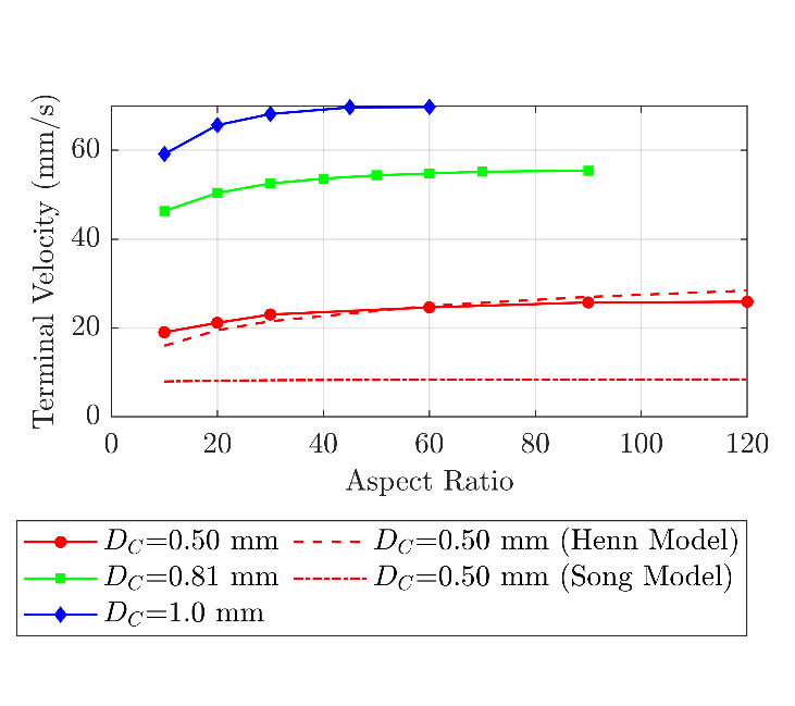
The terminal velocities of the straight rods for the studied diameters and aspect ratios are plotted in Figure 2. This figure shows that as the diameter and aspect ratio of the rod increase, the rod terminal velocity increases. The rate of the change in the terminal velocity decreases with an increase in aspect ratio, leading to an asymptotic behaviour at high aspect ratios. For instance, for , as the aspect ratio increases from 30 to 60, the terminal velocity increases by 4.3% (from 52.5 to 54.8 mm/s). However, the rod with an aspect ratio of 90, settling at 55.4 mm/s, settles only 1.2% faster than the rod with an aspect ratio of 60. This asymptotic trend also aligns with the findings from Jayaweera and Mason [43]. The primary reason for this behaviour is the insignificant effects of the finite ends of the rod on the drag coefficient at high aspect ratios [30]. Furthermore, this figure compares the terminal velocity of the rod with DC = 0.5 mm with the results of Song [23] and Henn [26] models. This comparison shows that the Song model [23] fails to accurately predict the terminal velocities of the rods within the ranges studied in this research since this model is developed for a wide range of particle geometries and consequently has lower accuracy for cylindrical particles. Henn model [26] aligns more closely with the experimental results obtained in this research. However, this model cannot still capture the asymptotic behaviour of the rod terminal velocity at high aspect ratios. The data points shown in Figure 2 are associated with a range of Reynolds numbers, which is calculated based on the diameter of the volume-equivalent sphere, between 0.07 and 1.75.
3.2. Curved Rods
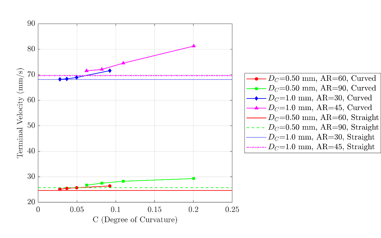
Figure 3 illustrates the terminal velocities of the curved rods at different degrees of curvature ranging between 0.03 and 0.20 (refer to equation (1) and Figure 1) and compares them with those of the straight rods. It can be seen from this figure that the terminal velocity of a curved rod is always larger than that of a straight rod with the same diameter and aspect ratio. This can be attributed to the smaller projected area of the curved rods compared to the straight rods with the same dimensions. Furthermore, the streamlines of the flow around the rod can align better with a curved geometry compared to a straight one, resulting in a reduced drag coefficient [30, 33, 34]. As the degree of curvature of the rod increases, or in other words, as the radius of curvature decreases, the terminal velocity increases. For the selection of curved rods considered in this study, the terminal velocity of the curved rods is up to 17% more than the terminal velocity of the straight. At very low degrees of curvature, the rod geometry tends to resemble a straight geometry, and the terminal velocity of the curved rod approaches that of a straight rod with the same diameter and aspect ratio.
2.3. V-shaped Rods
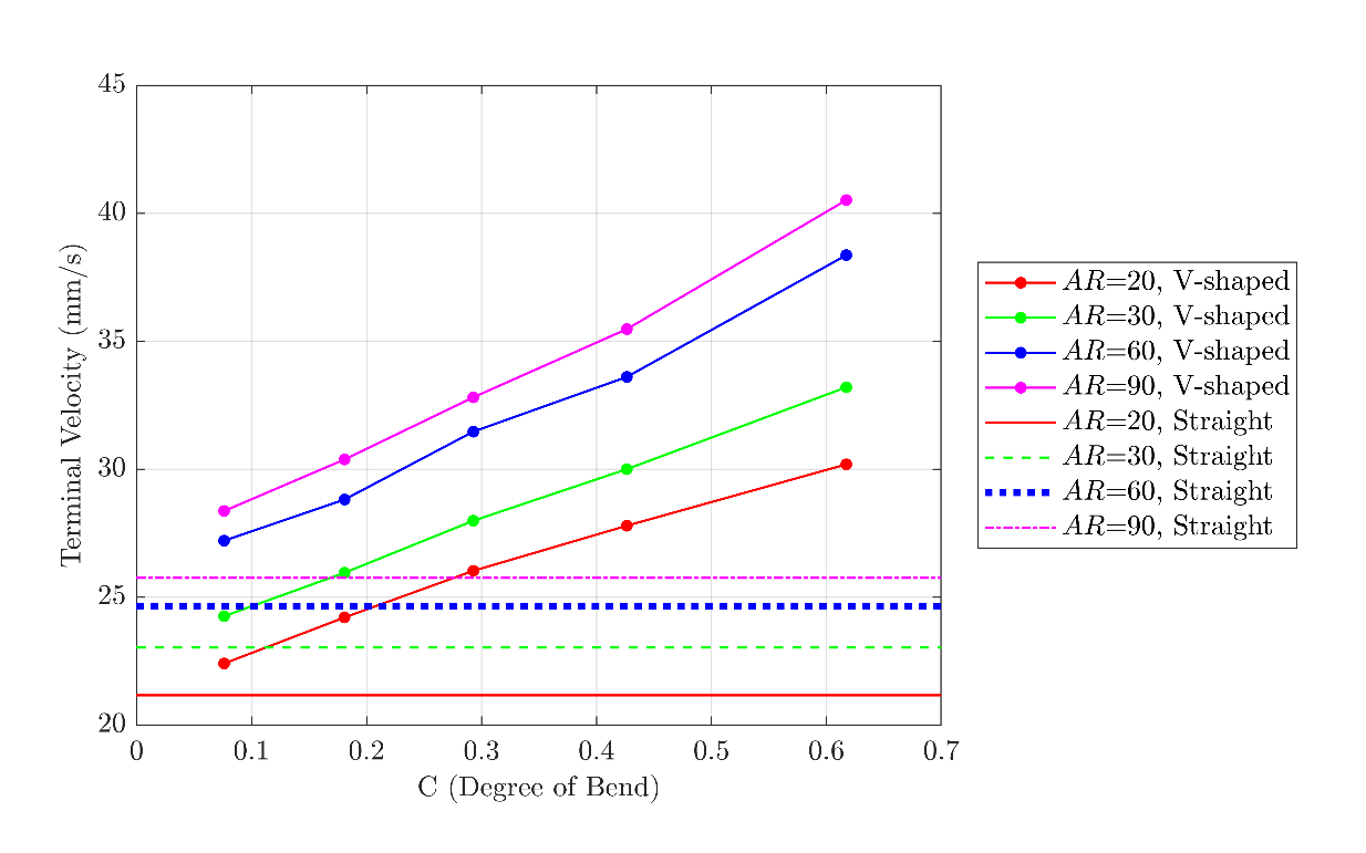
Straight rods with a diameter of 0.50 mm were bent with angles of 45, 70, 90, 110, and 135 degrees to make V-shaped rods with degrees of bend ranging between 0.08 and 0.62. The terminal velocities of the V-shaped rods are plotted in Figure 4 at different degrees of bend. The results demonstrate that an increase in the degree of bend, corresponding to a decrease in the bend angle, results in a larger terminal velocity. The V-shaped rods always settle faster than the straight rods with the same diameter and aspect ratio. In addition to the smaller projected area of a V-shaped rod compared to a straight rod with the same dimensions, the V-shaped rod resembles two smaller rods connected to each other at an angle of α. Each smaller rod has an inclined orientation, resulting in a higher settling velocity compared to a straight rod, which has a completely horizontal orientation. Moreover, the calculations show a maximum increase of 57% in the terminal velocity of the V-shaped rods relative to the straight rods within the ranges studied in this research. Similar to the curved rods, the terminal velocity of a V-shaped rod asymptotes to that of a straight rod with the same dimensions at very low degrees of bending.
2.4. U-shaped Rods
Based on the observations, the U-shaped rods adopt an oblique orientation during their fall, leading to a horizontal drift in their trajectory. In this study, the orientation of the U-shaped rods is defined by the angle between the U-shaped side arm and the horizontal direction, as shown in Figure 5. This angle is referred to as the “inclination angle”, and is denoted by θ.
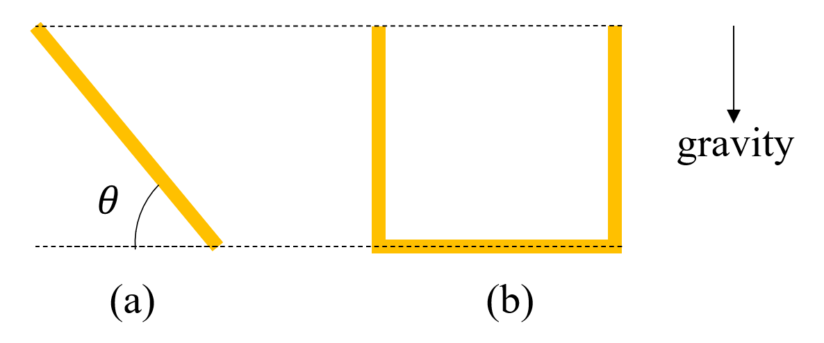
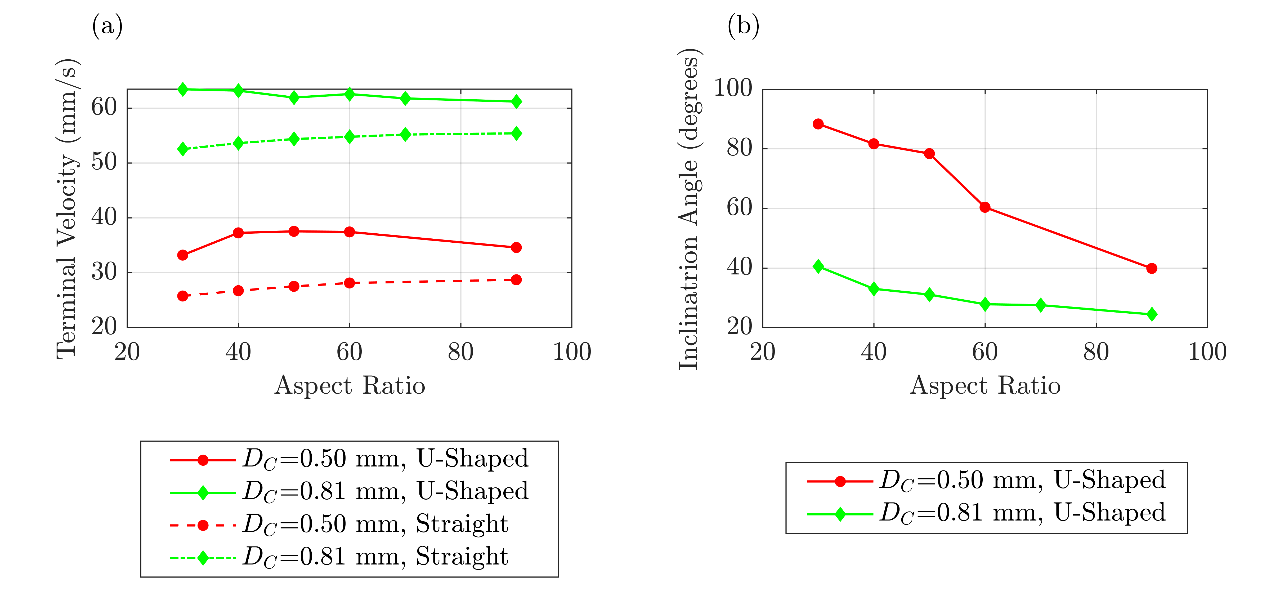
Figure 6 shows the variation of the U-shaped rod terminal velocity and inclination angle with the rod aspect ratio with all three arms equal (L1 = L2, L1 and L2 are represented in Figure 1). It can be seen from this figure that the terminal velocity of a U-shaped rod has a strong correlation with the inclination angle. For instance, for DC = 0.50 mm, the inclination angle changes from 90 degrees (vertical orientation) to 40 degrees (oblique orientation) as the aspect ratio increases. This increases the terminal velocity from 33 to 38 mm/s and decreases from 38 to 35 mm/s as the aspect ratio increases. However, the rod terminal velocity remains almost constant with the change in the aspect ratio for DC = 0.81 mm since its inclination angle changes only from 37 to 25 degrees. The observed trends in the terminal velocity of the U-shaped rod as the aspect ratio increases can be explained by the interplay between the size and orientation of the rod. As the aspect ratio of the rod increases, the inclination angle decreases, and the rod aligns more horizontally, which leads to a decrease in the terminal velocity. However, the side arms of the U-shaped rod increase in length with the increased aspect ratio, increasing the terminal velocity. The mentioned counteracting factors cause the U-shaped rod to exhibit either an initial rise and a subsequent decrease in the terminal velocity (as observed for DC = 0.50 mm) or an approximately constant value (as observed for DC = 0.81 mm) as the aspect ratio increases. Furthermore, Figure 6 demonstrates that the terminal velocity of a U-shaped rod is always larger than a straight rod with the same diameter and aspect ratio due to the non-zero inclination of the U-shaped rods. The maximum difference between the U-shaped and the straight rod terminal velocity is approximately 40% in this study.
4. Conclusions
The atmospheric settling of microplastic fibres is experimentally replicated by performing drop tests with straight, curved, V-shaped, and U-shaped cylindrical rods made of brass in a chamber filled with a quiescent glycerin-water mixture. The terminal velocity of the falling rods is determined by analysing the sequences of images captured from two cameras facing the two perpendicular sides of the chamber. The results indicate that the terminal velocity of a straight rod increases with the rod diameter and aspect ratio, showing an asymptotic behaviour towards a constant value at high aspect ratios, which is consistent with previous studies in the literature. Compared to straight rods, the curved and V-shaped rods with the same diameter and aspect ratio, i.e. the same rod but with various bent geometries, settle faster. The terminal velocity of the curved and the V-shaped rods increases with the degree of curvature and bend, which are associated with a decrease in the radius of curvature and bend angle for the curved and V-shaped rods, respectively. The terminal velocity of a U-shaped rod is determined by the trade-off between the length of its arms and the orientation of the rod. An increase in the aspect ratio of a U-shaped rod causes a decrease in its inclination angle and an increase in the length of the rod arms. This leads to the terminal velocity of the rod either first increasing and then decreasing or remaining constant as the rod aspect ratio increases. The terminal velocity of a U-shaped rod is consistently greater than that of a straight rod with the same diameter and aspect ratio. According to the results of this research, a general conclusion for rods of the same diameter and aspect ratio is as follows. V-shaped rods (or fibres) exhibit a higher vertical terminal velocity than U-shaped ones. The settling velocity of U-shaped rods (or fibres) exceeds that of curved ones, and curved geometries result in a terminal settling velocity that exceeds those of straight geometries. Given this difference in settling velocity, curved or bent microfibres may have a reduced transport distance by the atmosphere compared to straight fibres, depending on the degree of bend or curve.
Acknowledgments
This project is funded [in part] by the Northern Contaminants Program (CIRNAC, M-61) and the Government of Canada (ECCC, Grants and Contributions Award GCXE21S030).
References
[1] F. Petersen and J. A. Hubbart, "The occurrence and transport of microplastics: The state of the science," Science of the Total Environment, vol. 758, p. 143936, 2021. View Article
[2] Y. Zhang, S. Kang, S. Allen, D. Allen, T. Gao, and M. Sillanpää, "Atmospheric microplastics: A review on current status and perspectives," Earth-Science Reviews, vol. 203, p. 103118, 2020. View Article
[3] S. O'Brien et al., "There's something in the air: A review of sources, prevalence and behaviour of microplastics in the atmosphere," Science of The Total Environment, vol. 874, p. 162193, 2023. View Article
[4] S. Allen et al., "Evidence of free tropospheric and long-range transport of microplastic at Pic du Midi Observatory," Nature communications, vol. 12, no. 1, pp. 1-10, 2021. View Article
[5] M. Bergmann, S. Mützel, S. Primpke, M. B. Tekman, J. Trachsel, and G. Gerdts, "White and wonderful? Microplastics prevail in snow from the Alps to the Arctic," Science advances, vol. 5, no. 8, p. eaax1157, 2019. View Article
[6] S. L. Wright, J. Ulke, A. Font, K. L. A. Chan, and F. J. Kelly, "Atmospheric microplastic deposition in an urban environment and an evaluation of transport," Environment international, vol. 136, p. 105411, 2020. View Article
[7] I. Napper, F. Parker-Jurd, S. Wright, and R. Thompson, "Examining the release of synthetic microfibres to the environment via two major pathways: Atmospheric deposition and treated wastewater effluent," Science of The Total Environment, vol. 857, p. 159317, 2023. View Article
[8] J. C. Prata, "Airborne microplastics: consequences to human health?," Environmental pollution, vol. 234, pp. 115-126, 2018. View Article
[9] K. Liu, X. Wang, T. Fang, P. Xu, L. Zhu, and D. Li, "Source and potential risk assessment of suspended atmospheric microplastics in Shanghai," Science of the total environment, vol. 675, pp. 462-471, 2019. View Article
[10] S. Huang et al., "Detection and analysis of microplastics in human sputum," Environmental Science & Technology, vol. 56, no. 4, pp. 2476-2486, 2022. View Article
[11] G. F. Chen, Qingyuan; Wang, Jun, "Mini-review of microplastics in the atmosphere and their risks to humans," Science of the Total Environment, vol. 703, 2020. View Article
[12] P. Wu et al., "Absorption, distribution, metabolism, excretion and toxicity of microplastics in the human body and health implications," Journal of Hazardous Materials, vol. 437, p. 129361, 2022. View Article
[13] M. E. Çıtar Dazıroğlu and S. Bilici, "The hidden threat to food safety and human health: microplastics," Environment, Development and Sustainability, pp. 1-23, 2023. View Article
[14] R. W. Obbard, S. Sadri, Y. Q. Wong, A. A. Khitun, I. Baker, and R. C. Thompson, "Global warming releases microplastic legacy frozen in Arctic Sea ice," Earth's Future, vol. 2, no. 6, pp. 315-320, 2014. View Article
[15] F. Haque and C. Fan, "Fate of microplastics under the influence of climate change," Iscience, 2023. View Article
[16] L. Cai et al., "Characteristic of microplastics in the atmospheric fallout from Dongguan city, China: preliminary research and first evidence," Environmental Science and Pollution Research, vol. 24, no. 32, pp. 24928-24935, 2017. View Article
[17] R. Dris, J. Gasperi, V. Rocher, M. Saad, N. Renault, and B. Tassin, "Microplastic contamination in an urban area: a case study in Greater Paris," Environmental Chemistry, vol. 12, no. 5, pp. 592-599, 2015. View Article
[18] S. Allen et al., "Atmospheric transport and deposition of microplastics in a remote mountain catchment," Nature Geoscience, vol. 12, no. 5, pp. 339-344, 2019. View Article
[19] X. Long et al., "Efficient atmospheric transport of microplastics over Asia and adjacent oceans," Environmental Science & Technology, vol. 56, no. 10, pp. 6243-6252, 2022. View Article
[20] E. Ward, M. Gordon, R. Hanson, and L. M. Jantunen, "Modelling the effect of shape on atmospheric microplastic transport," Atmospheric Environment, p. 120458, 2024. View Article
View Article
[21] E. E. Michaelides and Z. Feng, "Drag Coefficients of Non-Spherical and Irregularly Shaped Particles," Journal of Fluids Engineering, vol. 145, no. 6, p. 060801, 2023. View Article
[22] G. H. Ganser, "A rational approach to drag prediction of spherical and nonspherical particles," Powder technology, vol. 77, no. 2, pp. 143-152, 1993. View Article
[23] X. Song, Z. Xu, G. Li, Z. Pang, and Z. Zhu, "A new model for predicting drag coefficient and settling velocity of spherical and non-spherical particle in Newtonian fluid," Powder Technology, vol. 321, pp. 242-250, 2017. View Article
[24] G. Bagheri and C. Bonadonna, "On the drag of freely falling non-spherical particles (vol 30, pg 526, 2016)," Powder Technology, vol. 349, pp. 108-108, 2019. View Article
[25] J. Zhang and C. E. Choi, "Improved settling velocity for microplastic fibers: A new shape-dependent drag model," Environmental science & technology, vol. 56, no. 2, pp. 962-973, 2021. View Article
[26] A. R. Henn, "Calculation of the stokes and aerodynamic equivalent diameters of a short reinforcing fiber," Particle & particle systems characterization, vol. 13, no. 4, pp. 249-253, 1996. View Article
[27] A. Khalili and B. Liu, "Stokes' paradox: creeping flow past a two-dimensional cylinder in an infinite domain," Journal of Fluid Mechanics, vol. 817, pp. 374-387, 2017. View Article
[28] B. Huner and R. Hussey, "Cylinder drag at low Reynolds number," The Physics of Fluids, vol. 20, no. 8, pp. 1211-1218, 1977. View Article
[29] S. Sen, S. Mittal, and G. Biswas, "Steady separated flow past a circular cylinder at low Reynolds numbers," Journal of Fluid Mechanics, vol. 620, pp. 89-119, 2009. View Article
[30] A. Hamidi, D. Daramsing, M. D. Gordon, L. M. Jantunen, and R. E. Hanson, "Straight and curved cylindrical rods settling in quiescent fluid with application to atmospheric microplastics," Experiments in Fluids, vol. 65, no. 6, p. 81, 2024. View Article
[31] S. Dehghani, F. Moore, and R. Akhbarizadeh, "Microplastic pollution in deposited urban dust, Tehran metropolis, Iran," Environmental Science and Pollution Research, vol. 24, no. 25, pp. 20360-20371, 2017. View Article
[32] S. Xiao, Y. Cui, J. Brahney, N. M. Mahowald, and Q. Li, "Long-distance atmospheric transport of microplastic fibres influenced by their shapes," Nature Geoscience, pp. 1-8, 2023. View Article
[33] X. Rong, D. Qi, G. He, J. Zhu, and T. Scott, "Single curved fiber sedimentation under gravity," Computers & Mathematics with Applications, vol. 55, no. 7, pp. 1560-1567, 2008. View Article
[34] X. Yang, Y. Wang, Y. Li, Y. Cao, Y. Zhou, and Y. Huang, "Experimental research on the settling property of slender fiber particles under the influence of multiple factors," Powder Technology, vol. 405, p. 117543, 2022. View Article
[35] T. H. Nguyen, T.-C. Kieu-Le, F. H. Tang, and F. Maggi, "Controlling factors of microplastic fibre settling through a water column," Science of The Total Environment, p. 156011, 2022. View Article
[36] B. Marchetti et al., "Deformation of a flexible fiber settling in a quiescent viscous fluid," Physical Review Fluids, vol. 3, no. 10, p. 104102, 2018. View Article
[37] A. Roy, R. J. Hamati, L. Tierney, D. L. Koch, and G. A. Voth, "Inertial torques and a symmetry breaking orientational transition in the sedimentation of slender fibres," Journal of Fluid Mechanics, vol. 875, pp. 576-596, 2019. View Article
[38] B. R. Angle, M. J. Rau, and M. L. Byron, "Effect of mass distribution on falling cylindrical particles at intermediate Reynolds numbers," in Fluids Engineering Division Summer Meeting, 2019, vol. 59087: American Society of Mechanical Engineers, p. V005T05A065. View Article
[39] M. Klein and E. K. Fischer, "Microplastic abundance in atmospheric deposition within the Metropolitan area of Hamburg, Germany," Science of the Total Environment, vol. 685, pp. 96-103, 2019. View Article
[40] R. Dris et al., "A first overview of textile fibers, including microplastics, in indoor and outdoor environments," Environmental pollution, vol. 221, pp. 453-458, 2017. View Article
[41] B. Roblin, M. Ryan, A. Vreugdenhil, and J. Aherne, "Ambient atmospheric deposition of anthropogenic microfibers and microplastics on the western periphery of Europe (Ireland)," Environmental science & technology, vol. 54, no. 18, pp. 11100-11108, 2020. View Article
[42] S. Xiao, Y. Cui, J. Brahney, N. Mahowald, and Q. Li, "Long-distance atmospheric transport of microplastic fibers depends on their shapes," 2023. View Article
[43] K. Jayaweera and B. Mason, "The behaviour of freely falling cylinders and cones in a viscous fluid," Journal of Fluid Mechanics, vol. 22, no. 4, pp. 709-720, 1965. View Article
View Article
[1] F. Petersen and J. A. Hubbart, "The occurrence and transport of microplastics: The state of the science," Science of the Total Environment, vol. 758, p. 143936, 2021. View Article
[2] Y. Zhang, S. Kang, S. Allen, D. Allen, T. Gao, and M. Sillanpää, "Atmospheric microplastics: A review on current status and perspectives," Earth-Science Reviews, vol. 203, p. 103118, 2020. View Article
[3] S. O'Brien et al., "There's something in the air: A review of sources, prevalence and behaviour of microplastics in the atmosphere," Science of The Total Environment, vol. 874, p. 162193, 2023. View Article
[4] S. Allen et al., "Evidence of free tropospheric and long-range transport of microplastic at Pic du Midi Observatory," Nature communications, vol. 12, no. 1, pp. 1-10, 2021. View Article
[5] M. Bergmann, S. Mützel, S. Primpke, M. B. Tekman, J. Trachsel, and G. Gerdts, "White and wonderful? Microplastics prevail in snow from the Alps to the Arctic," Science advances, vol. 5, no. 8, p. eaax1157, 2019. View Article
[6] S. L. Wright, J. Ulke, A. Font, K. L. A. Chan, and F. J. Kelly, "Atmospheric microplastic deposition in an urban environment and an evaluation of transport," Environment international, vol. 136, p. 105411, 2020. View Article
[7] I. Napper, F. Parker-Jurd, S. Wright, and R. Thompson, "Examining the release of synthetic microfibres to the environment via two major pathways: Atmospheric deposition and treated wastewater effluent," Science of The Total Environment, vol. 857, p. 159317, 2023. View Article
[8] J. C. Prata, "Airborne microplastics: consequences to human health?," Environmental pollution, vol. 234, pp. 115-126, 2018. View Article
[9] K. Liu, X. Wang, T. Fang, P. Xu, L. Zhu, and D. Li, "Source and potential risk assessment of suspended atmospheric microplastics in Shanghai," Science of the total environment, vol. 675, pp. 462-471, 2019. View Article
[10] S. Huang et al., "Detection and analysis of microplastics in human sputum," Environmental Science & Technology, vol. 56, no. 4, pp. 2476-2486, 2022. View Article
[11] G. F. Chen, Qingyuan; Wang, Jun, "Mini-review of microplastics in the atmosphere and their risks to humans," Science of the Total Environment, vol. 703, 2020. View Article
[12] P. Wu et al., "Absorption, distribution, metabolism, excretion and toxicity of microplastics in the human body and health implications," Journal of Hazardous Materials, vol. 437, p. 129361, 2022. View Article
[13] M. E. Çıtar Dazıroğlu and S. Bilici, "The hidden threat to food safety and human health: microplastics," Environment, Development and Sustainability, pp. 1-23, 2023. View Article
[14] R. W. Obbard, S. Sadri, Y. Q. Wong, A. A. Khitun, I. Baker, and R. C. Thompson, "Global warming releases microplastic legacy frozen in Arctic Sea ice," Earth's Future, vol. 2, no. 6, pp. 315-320, 2014. View Article
[15] F. Haque and C. Fan, "Fate of microplastics under the influence of climate change," Iscience, 2023. View Article
[16] L. Cai et al., "Characteristic of microplastics in the atmospheric fallout from Dongguan city, China: preliminary research and first evidence," Environmental Science and Pollution Research, vol. 24, no. 32, pp. 24928-24935, 2017. View Article
[17] R. Dris, J. Gasperi, V. Rocher, M. Saad, N. Renault, and B. Tassin, "Microplastic contamination in an urban area: a case study in Greater Paris," Environmental Chemistry, vol. 12, no. 5, pp. 592-599, 2015. View Article
[18] S. Allen et al., "Atmospheric transport and deposition of microplastics in a remote mountain catchment," Nature Geoscience, vol. 12, no. 5, pp. 339-344, 2019. View Article
[19] X. Long et al., "Efficient atmospheric transport of microplastics over Asia and adjacent oceans," Environmental Science & Technology, vol. 56, no. 10, pp. 6243-6252, 2022. View Article
[20] E. Ward, M. Gordon, R. Hanson, and L. M. Jantunen, "Modelling the effect of shape on atmospheric microplastic transport," Atmospheric Environment, p. 120458, 2024. View Article
View Article[21] E. E. Michaelides and Z. Feng, "Drag Coefficients of Non-Spherical and Irregularly Shaped Particles," Journal of Fluids Engineering, vol. 145, no. 6, p. 060801, 2023. View Article
[22] G. H. Ganser, "A rational approach to drag prediction of spherical and nonspherical particles," Powder technology, vol. 77, no. 2, pp. 143-152, 1993. View Article
[23] X. Song, Z. Xu, G. Li, Z. Pang, and Z. Zhu, "A new model for predicting drag coefficient and settling velocity of spherical and non-spherical particle in Newtonian fluid," Powder Technology, vol. 321, pp. 242-250, 2017. View Article
[24] G. Bagheri and C. Bonadonna, "On the drag of freely falling non-spherical particles (vol 30, pg 526, 2016)," Powder Technology, vol. 349, pp. 108-108, 2019. View Article
[25] J. Zhang and C. E. Choi, "Improved settling velocity for microplastic fibers: A new shape-dependent drag model," Environmental science & technology, vol. 56, no. 2, pp. 962-973, 2021. View Article
[26] A. R. Henn, "Calculation of the stokes and aerodynamic equivalent diameters of a short reinforcing fiber," Particle & particle systems characterization, vol. 13, no. 4, pp. 249-253, 1996. View Article
[27] A. Khalili and B. Liu, "Stokes' paradox: creeping flow past a two-dimensional cylinder in an infinite domain," Journal of Fluid Mechanics, vol. 817, pp. 374-387, 2017. View Article
[28] B. Huner and R. Hussey, "Cylinder drag at low Reynolds number," The Physics of Fluids, vol. 20, no. 8, pp. 1211-1218, 1977. View Article
[29] S. Sen, S. Mittal, and G. Biswas, "Steady separated flow past a circular cylinder at low Reynolds numbers," Journal of Fluid Mechanics, vol. 620, pp. 89-119, 2009. View Article
[30] A. Hamidi, D. Daramsing, M. D. Gordon, L. M. Jantunen, and R. E. Hanson, "Straight and curved cylindrical rods settling in quiescent fluid with application to atmospheric microplastics," Experiments in Fluids, vol. 65, no. 6, p. 81, 2024. View Article
[31] S. Dehghani, F. Moore, and R. Akhbarizadeh, "Microplastic pollution in deposited urban dust, Tehran metropolis, Iran," Environmental Science and Pollution Research, vol. 24, no. 25, pp. 20360-20371, 2017. View Article
[32] S. Xiao, Y. Cui, J. Brahney, N. M. Mahowald, and Q. Li, "Long-distance atmospheric transport of microplastic fibres influenced by their shapes," Nature Geoscience, pp. 1-8, 2023. View Article
[33] X. Rong, D. Qi, G. He, J. Zhu, and T. Scott, "Single curved fiber sedimentation under gravity," Computers & Mathematics with Applications, vol. 55, no. 7, pp. 1560-1567, 2008. View Article
[34] X. Yang, Y. Wang, Y. Li, Y. Cao, Y. Zhou, and Y. Huang, "Experimental research on the settling property of slender fiber particles under the influence of multiple factors," Powder Technology, vol. 405, p. 117543, 2022. View Article
[35] T. H. Nguyen, T.-C. Kieu-Le, F. H. Tang, and F. Maggi, "Controlling factors of microplastic fibre settling through a water column," Science of The Total Environment, p. 156011, 2022. View Article
[36] B. Marchetti et al., "Deformation of a flexible fiber settling in a quiescent viscous fluid," Physical Review Fluids, vol. 3, no. 10, p. 104102, 2018. View Article
[37] A. Roy, R. J. Hamati, L. Tierney, D. L. Koch, and G. A. Voth, "Inertial torques and a symmetry breaking orientational transition in the sedimentation of slender fibres," Journal of Fluid Mechanics, vol. 875, pp. 576-596, 2019. View Article
[38] B. R. Angle, M. J. Rau, and M. L. Byron, "Effect of mass distribution on falling cylindrical particles at intermediate Reynolds numbers," in Fluids Engineering Division Summer Meeting, 2019, vol. 59087: American Society of Mechanical Engineers, p. V005T05A065. View Article
[39] M. Klein and E. K. Fischer, "Microplastic abundance in atmospheric deposition within the Metropolitan area of Hamburg, Germany," Science of the Total Environment, vol. 685, pp. 96-103, 2019. View Article
[40] R. Dris et al., "A first overview of textile fibers, including microplastics, in indoor and outdoor environments," Environmental pollution, vol. 221, pp. 453-458, 2017. View Article
[41] B. Roblin, M. Ryan, A. Vreugdenhil, and J. Aherne, "Ambient atmospheric deposition of anthropogenic microfibers and microplastics on the western periphery of Europe (Ireland)," Environmental science & technology, vol. 54, no. 18, pp. 11100-11108, 2020. View Article
[42] S. Xiao, Y. Cui, J. Brahney, N. Mahowald, and Q. Li, "Long-distance atmospheric transport of microplastic fibers depends on their shapes," 2023. View Article
[43] K. Jayaweera and B. Mason, "The behaviour of freely falling cylinders and cones in a viscous fluid," Journal of Fluid Mechanics, vol. 22, no. 4, pp. 709-720, 1965. View Article
View Article