Journal of Fluid Flow, Heat and Mass Transfer (JFFHMT)
ISSN: 2368-6111

Volume 10 - Year 2023 - Pages 45-51
DOI: 10.11159/jffhmt.2023.006
Numerical and Experimental Study of The Viscous Dissipation of Oil inside the Electric Motor’s Gap
Ahmed M. Teamah1, Mohamed S. Hamed1
1 McMaster University, Department of Mechanical Engineering
Thermal Processing Laboratory
1280 Main Street West, Hamilton, Ontario, Canada L8S-4K1
teamaha@mcmaster.ca
Abstract - A numerical study has been carried out to quantify the level of viscous dissipation inside an electrical motor. The study has been performed using an in-house computational model. This paper presents the effect of several geometrical and operating parameters on the level of viscous dissipation generated within the stator-rotor gap. The geometrical parameters considered in this study are the gap size, rotor length and the stator inner diameter, varied in the range of 0.25-1.4 mm, 140-1120 mm and 55-375 mm, respectively. The operating parameter considered in this study is the rotor rotational speed and oil level, which was varied in the range of 900-3600 rpm and 50-100 %, respectively. The numerical results have been validated using experimental data. Results indicated that the amount of heat generated due to viscous dissipation is directly proportional to the stator diameter and rotor rotational speed, and inversely proportional to the gap thickness.
Keywords: Viscous dissipation, Electric motors, Taylor Couette flow, Thermal performance.
© Copyright 2023 Authors - This is an Open Access article published under the Creative Commons Attribution License terms Creative Commons Attribution License terms. Unrestricted use, distribution, and reproduction in any medium are permitted, provided the original work is properly cited.
Date Received: 2023-05-27
Date Revised: 2023-06-30
Date Accepted: 2023-07-05
Date Published: 2023-08-08
1. Introduction
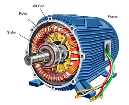
A typical electric motor consists of several components shown in Figure 1. The main components are the stator and rotor within which a gap is present. Electric motors generate heat losses due to electric current passing through the motor windage resistance and due to viscous dissipation within the rotor-stator gap. The gap thickness and the stator inner diameter could dramatically affect the amount of heat generated due to viscous dissipation especially if the gap is filled with a high viscosity lubricating fluid. To minimize the possibility of electric motors overheating, the motor design should be focused on minimizing the total amount of heat losses generated within the motor.
2. Literature Review
The flow of the lubricating fluid within the rotor-stator gap is commonly referred to as a Taylor-Couette flow because the typical Taylor-Couette flow is a flow between two concentric cylinders. Many researchers have investigated the Taylor-Couette flow. The work reported in [2 - 6] was focused on the heat transfer and fluid flow of a single-phase Taylor-Couette flow considering the stability of such flow. The previous studies showed that, the increase in the rotational speed enhanced the heat transfer inside the gap.
A review of flow between two concentric cylinders was reported in [7]. [8] investigated a multi-phase Taylor-Couette flow of air and oil within two concentric cylinders. This study proved that the optimum oil volume percentage was 65% for heat transfer inside the gap. The higher the rotational speed, the higher the rate of heat transfer inside the gap.
[9] studied the effect of adding a set of longitudinal slots along the outer concentric cylinder. The slots studied were rectangular, trapezoidal and elliptical in shape. The elliptical shaped slots gave the best heat transfer behaviour.
[10] studied transient heat transfer inside a motor gap. To the best of the authors’ knowledge, there has not been any studies of the effect of gap size and rotational speed on the level of viscous dissipation within a motor gap.
3. Problem Definition
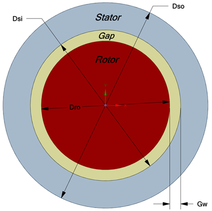
The problem of interest involves the estimation of heat generated due to the viscous dissipation within the rotor-stator gap of an electric motor shown in Figure 2.
The gap length is varying from 0.14 to 1.12 m. The rotor is rotating at a constant speed (N). All solid surfaces are assumed smooth. The gap is filled with an Enduratex EP150 oil. The oil properties were taken from the material data sheet reported in [11]. The motor is fully submerged in oil.
4. Mathematical Model
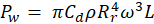
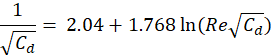
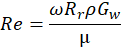
An in-house numerical model has been used to estimate the amount of viscous dissipation developed with the gap at fully filled with oil volume percentage of 100%. The amount of viscous dissipation (Pw) has been calculated using equation (1) from [12]. The skin friction coefficient (Cd) was calculated from equation (2) from [12] using an iterative method. Reynolds number (Re) is defined in equation (3) using the gap thickness as the characteristic length scale. The stator was assumed insulated, and the rotor was assumed rotating with a constant rotational speed.
The variables included in equations (1)-(3) are defined as follows:
- Pw is the heat rate generated due to viscous dissipation in W.
- Cd is the skin friction coefficient.
- ρ is the oil density in kg/m3 and is calculated at the average oil temperature within the gap.
- Rr=Dro/2 is the rotor outer radius in m.
- ω=2πN/60 is the rotor angular velocity in rad/sec.
- L is the rotor length in m.
- Re is the Reynolds number.
- Gw is the gap width in m and is defined as shown in Figure 2.
- µ is the dynamic viscosity of oil in Pa.sec and is calculated at the average temperature across the gap
4.1. Validation of The Numerical Results
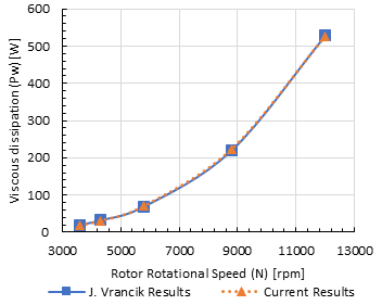
Validation of the present numerical results has been carried out using experimental and numerical data reported in [12]. [12] studied viscous dissipation inside a motor gap filled with air. The length and radius of the rotor were 0.1142 m and 0.1 m, respectively. The gap width was 0.63 mm. The rotor rotational speed varied from 3600 rpm to 12000 rpm. The corresponding Reynolds number (Re) ranged from 1500 to 5000. The maximum deviation found between the present numerical results and the data reported in [12] is about 3.5%, as illustrated in Figure 3.
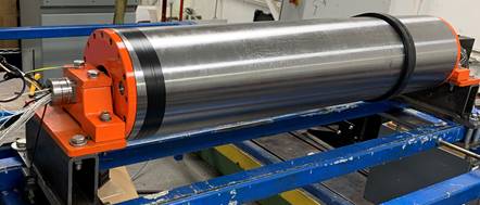
In addition, a test rig has been constructed at the industrial partner Vander Graaf (VDG) as shown in Figure 4. An actual motor was inserted inside a Self-Contained Drum Motor Drive System (SCDMDS). The SCDMDS is one of the applications of the current study. The SCDMDS has been discussed in deep details as in [13]. The test rig constructed for the estimation of the viscous dissipation does not have a gearbox inside the drum but just a motor is running inside oil.
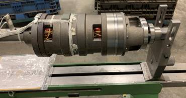
Figure 5 shows the electrical motor and thermocouples placed inside the casing of Figure 4. The oil has been inserted inside the casing in order to fill the gap between the motor rotor and stator. The amount of heat from viscous dissipation has been estimated using a wattage meter connected to the variable frequency drive (VFD) running at no load inside the casing.
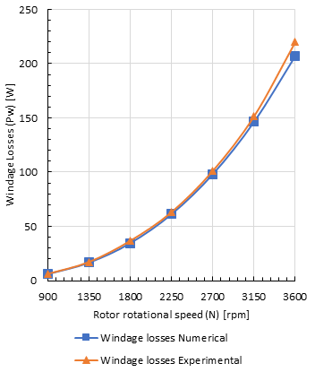
The rotor speed has been varied by adjusting the frequency to the VFD from 900 to 3600 rpm. The Gw, Dsi, L and OV were kept constant at 0.25 mm, 55 mm, 140 mm and 100% respectively. Figure 6 shows a great agreement between the current experimental values and the numerical estimated values of the viscous dissipation inside the gap with maximum deviation of about 6 %.
5. Results and Discussions
The parameters investigated in the present study are the gap size [Gw], the stator inner diameter [Dsi], the rotor length [L], oil level [OV], and the rotor rotational speed [N]. These parameters have been varied in the ranges of 0.25-1.4 mm, 55-375 mm, 0.14-1.12 m, 50-100% and 900-3600 rpm, respectively. The effect of these parameters on viscous dissipation [Pw] has been investigated.
5.1. Effect of the gap size on the viscous dissipation
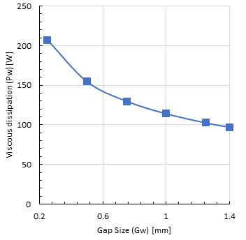
Figure 7 shows the effect of the gap size on the viscous dissipation at constant stator inner diameter of 55 mm, rotor length of 0.14 m, oil level is 100% and rotor rotational speed of 3600 rpm. Results indicate that the increase in gap size reduces the viscous dissipation where the best gap thickness is the largest of 1.4 mm. That is explained from equation (3) as the Reynolds number (Re) is increased with increasing the gap size. Hence, the skin friction factor (Cd) is reduced as from equation (2) and in return the viscous dissipation is decreased as from equation (1). The rate of reduction in the viscous dissipation is not a linear relation due to the fact of that the skin friction factor (Cd) is not directly proportional with the Reynolds number (Re).
5.2. Effect of the stator inner diameter on the viscous dissipation
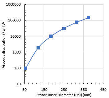
Figure 8 shows the effect of the stator inner diameter on the viscous dissipation at constant gap size of 1.4 mm, rotor length of 0.14 m, oil level of 100% and rotor rotational speed of 3600 rpm.
The results showed that with increasing the stator inner diameter (Dsi), the viscous dissipation increased dramatically. The viscous dissipation is increased as from equation (1) as the rotor radius (Rr) is raised to the power of 4.
The increase in the rotor radius (Rr) increases the Reynolds number which reduces the skin friction factor (Cd). However, the effect of the skin friction factor (Cd) is not dominant in changing the viscous dissipation as it is just raised to the power of 1. So, the dominant parameter in the calculations of the viscous dissipation is the stator and rotor radius.
5.3. Effect of the rotor rotational speed on the viscous dissipation
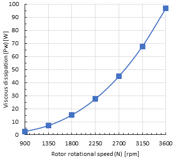
Figure 9 shows the effect of the rotor rotational speed on the viscous dissipation at constant gap size of 1.4 mm, stator inner diameter of 55 mm, rotor length of 0.14 m and oil level of 100%. Results indicated that the increase in the rotor rotational speed increases the viscous dissipation inside the motor gap. As shown in Figure 9, the highest rotor rotational speed of 3600 rpm has the largest amount of viscous dissipation.
As clear from equation (1), the increase in the rotor rotational speed increases the viscous dissipation significantly as the angular velocity (ω) is raised to the power 3.
5.4. Effect of the rotor length on the viscous dissipation
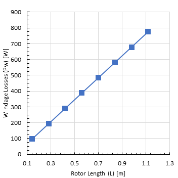
Figure 10 shows the effect of the rotor length on the viscous dissipation at constant gap size of 1.4 mm, stator inner diameter of 55 mm, rotor rotational speed of 3600 rpm and oil level of 100%.
The increase in the rotor length from 0.12 to 1.12 m increases the viscous dissipation from 100 to 775 W. The relation between the rotor length and the viscous dissipation is linear as shown in Figure 10. The trend of this variation comes from the fact that the length of the rotor increases linearly the lateral surface area subjected to this viscous dissipation. Hence, the increase in the rotor length increases the amount of heat generated from the viscous dissipation linearly.
5.5. Effect of the oil level on the viscous dissipation
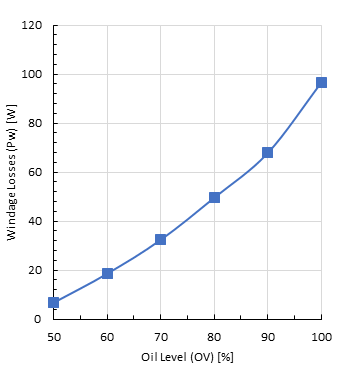
Figure 11 shows the effect of the oil level on the viscous dissipation at constant gap size of 1.4 mm, stator inner diameter of 55 mm, rotor length of 0.14 m and rotor rotational speed of 3600 rpm. This section of the results has been carried out experimentally using the test rig shown in Figure 4 by varying the amount of oil inside the casing.
Figure 11 shows the effect of varying the oil level from 50 to 100%, i.e., fully filled with oil, on the viscous dissipation between the motor rotor and the stator. The increase in the oil level inside the gap of the motor, increases the amount of heat generated from the viscous dissipation as clear from Figure 11.
The rise in the amount of heat from the viscous dissipation originates from the fact that the oil has very high viscosity compared to the air. So, the presence of lower amount of oil filling the gap means that the air is filling the other portion of this volume. The rise in the oil level means more friction due to the higher oil viscosity of oil and hence more viscous dissipation is generated.
6. Summary and Conclusions
The paper covered the effect of multiple geometrical and operational parameters on the amount of viscous dissipation inside the motor gap. One can easily note that increasing the gap size reduced the viscous dissipation inside the gap. Also, the reduction in the rotor radius and rotor rotational speed decreased viscous dissipation within the motor gap. The increase in the rotor length or the oil level increases the amount of heat generated from the viscous dissipation. The most dominant parameter is the rotor radius as a small change (increase) in the rotor radius resulted in a significant change (increase) in viscous dissipation.
7. Acknowledgement
The authors would like to acknowledge our industrial partner Vander Graaf (VDG) and the financial support of this work received from Mathematics of Information Technology and Complex Systems (Mitacs).
References
[1] Electrical Motor Components. Available: View Article View Article
[2] C. D. Andereck, S. S. Liu, and H. L. Swinney, "Flow regimes in a circular Couette system with independently rotating cylinders," Journal of Fluid Mechanics, vol. 164, pp. 155-183, 1986. View Article
[3] P. S. Marcus, "Simulation of Taylor-Couette flow. Part 1. Numerical methods and comparison with experiment," Journal of Fluid Mechanics, vol. 146, pp. 45-64, 1984. View Article
[4] D. Paghdar, S. Jogee, and K. Anupindi, "Large-eddy simulation of counter-rotating Taylor-Couette flow: The effects of angular velocity and eccentricity," International Journal of Heat and Fluid Flow, vol. 81, p. 108514, 2020/02/01/ 2020. View Article
[5] U. Naseem, M. B. Awan, B. Saeed, N. Abbas, S. Nawaz, and M. Hussain, "Experimental investigation of flow instabilities in a wide gap turbulent rotating Taylor-Couette flow," Case Studies in Thermal Engineering, vol. 14, p. 100449, 2019/09/01/ 2019. View Article
[6] S. Dong, "Direct numerical simulation of turbulent Taylor-Couette flow," Journal of Fluid Mechanics, vol. 587, pp. 373-393, 2007. View Article
[7] M. Fénot, Y. Bertin, E. Dorignac, and G. Lalizel, "A review of heat transfer between concentric rotating cylinders with or without axial flow," International Journal of Thermal Sciences - INT J THERM SCI, vol. 50, pp. 1138-1155, 07/01 2011. View Article
[8] A. M. Teamah and M. S. Hamed, "Investigation of transient multiphase Taylor-Couette flow," Alexandria Engineering Journal, vol. 61, no. 4, pp. 2723-2738, 2022/04/01/ 2022. View Article
[9] S.-l. Sun, D. Liu, Y.-Z. Wang, S. M. R. S. Naqvi, and H.-B. Kim, "Heat transfer characteristics of Taylor-Couette flow with axially distributed slits using field synergy principle and entropy generation analysis," International Communications in Heat and Mass Transfer, vol. 129, p. 105699, 2021/12/01/ 2021. View Article
[10] M. L. Hosain, R. Bel Fdhila, and K. Rönnberg, "Taylor-Couette flow and transient heat transfer inside the annulus air-gap of rotating electrical machines," Applied Energy, vol. 207, pp. 624-633, 2017/12/01/ 2017. View Article
[11] Oil Enduratex EP 150. Available: https://lubricants.petro-canada.com/en-ae/brand/enduratex-ep#4c438c61-0a61-4851-b43d-b1bfffe8539d
[12] J. E. Vrancik, U. S. N. Aeronautics, S. Administration, and L. R. Center, Prediction of Windage Power Loss in Alternators. National Aeronautics and Space Administration, 1968. View Article
[13] A. M. Teamah and M. S. Hamed, "Numerical investigation of thermal losses within an internal gear train submerged in a multiphase flow and enclosed in a rotating casing," International Journal of Thermofluids, vol. 15, p. 100188, 2022/08/01/ 2022. View Article