Journal of Fluid Flow, Heat and Mass Transfer (JFFHMT)
ISSN: 2368-6111

Volume 11 - Year 2024 - Pages 21-28
DOI: 10.11159/jffhmt.2024.003
Numerical Study of a Planar Micromixer with Circular and Fin Obstacles
Md Readul Mahmud
Independent University, Bangladesh, Department of Physical Sciences
Plot 16, Block B, Aftabuddin Ahmed Road
Bashundhara Residential Area, Dhaka 1229
mahmud.readul@iub.edu.bd
Abstract - The design and characterization of a passive planar O mixer with two different kinds of barriers to improve mixing performance are reported in this study. The computational fluid dynamics (CFD) program ANSYS 15 is used to perform computational studies on mixing and fluid flow in microchannels over a broad range of Reynolds numbers, from 1 to 100. The outcomes demonstrate that the O mixer with obstacles performs significantly better at mixing than the O mixer without obstacles. The explanation is that obstacles cause the fluid path length to increase, giving the fluids more time to diffuse. The O mixer with circular and fin obstacles is three times more efficient than the O mixer without obstacles in all scenarios. Due to the absence of any obstructions within the channel, the O mixer has the lowest pressure drop. The O mixer with circular & fin obstacles is the most economical one since it has the lowest mixing cost, which is a crucial feature for incorporation into intricate, cascading microfluidic systems. The proposed O mixer with obstacles can be easily manufactured and integrated into devices for a variety of macromixing applications due to its low mixed cost and simple planar construction.
Keywords: CFD, Efficiency, Micromixer, Mixing cost, Planar mixer.
© Copyright 2024 Authors - This is an Open Access article published under the Creative Commons Attribution License terms Creative Commons Attribution License terms. Unrestricted use, distribution, and reproduction in any medium are permitted, provided the original work is properly cited.
Date Received: 2022-06-08
Date Revised: 2023-01-23
Date Accepted: 2024-01-30
Date Published: 2024-02-05
1. Introduction
Mixing various substances is a typical act of regular day-to-day activity yet it is generally difficult to accomplish good or homogeneous blending. Microdevices and micromixers serve the purpose of obtaining excellent mixing on a micro-scale [1]. Micromixers have a high surface-to-volume proportion because of their small dimension, which is a defining characteristic compared to conventional-size chemical process equipment [2]. The flow inside the micromixer is usually laminar due to its small size and mixing usually depends on molecular diffusion at a low Reynolds number [3]. Therefore, good mixing takes a long time and a long channel length. The application of microdevices and micromixers is increasing daily in various applications such as the chemical industry, biomedical industry, and biochemical fields [4-6]. Process safety, inexpensive production expenses, less chemical and reagent consumption, enhanced process control, faster process optimization, simple implementation, and easy scale-up by "numbering up" are just a few of the many benefits of micromixers [7-11].
Mixers are broadly divided into two types, active and passive [12]. There are always active parts in active mixers to achieve excellent mixing [13]. On the other hand, passive mixers utilize various channel sizes and lengths, and unique geometric configurations to compensate for the absence of active elements [14]. The passive mixer increases the contact area between fluids and promotes molecular diffusion. The primary categories of active mixers include thermal, time-pulse, acoustic, magnetic, electrodynamic, dielectrophoretic, pressure perturbation, and other varieties [15-16].
T shape and Y shape mixers are the oldest mixers designed and analyzed by many researchers in recent years [17-21]. Numerical and/or experimental flow regimes, the influence of secondary flow, vortex flow, and mixing performance have been computed extensively in recent years [22-24]. Generally, the T mixer provides poor efficacy at low Reynolds numbers due to the laminar nature of flow (also the absence of advection). Hence different kinds of obstacles and barriers are placed inside the channel to create chaotic advection and as a result, increase the efficiency. Many authors introduce various sizes and shapes of obstacles in T mixers which increase efficacy but result in high-pressure drop [25-28]. Four passive micromixers (G1, G2, G3, and G4) were studied but G1 and G4 designs provided a high mixing due to the presence of chaotic advection [29]. A T mixer having staggered fins has been numerically studied for a set of parametric (spacing of fins, angle of inclination, Reynolds number, and width of fins) [30]. M. Nimafar et. al. [31] reports a basic O-type mixer for low Reynolds numbers (0.08<Re<4.16) and after 15 mm along the channel length, the experimental mixing efficiency is about 81% and 17.6% at Re=0.803 and Re=4.166, respectively.
Several groups have studied mixers introducing barriers and baffles that modify the overall channel geometry [32-34]. A. A. S. Bhagat et al. [35] used circular, triangular, and diamond impediments to boost efficiency at Re=1. A range of diamond obstacles was added to the designs by Both Shim et. al. [36] and Chung et. al. [37], resulting in good efficiency at Re=200.
In recent years, ridges and grooves have been introduced to achieve chaotic mixing. In chaotic-advection micromixers, 3D channel structure [38-39], and planar design [40] were used to enhance fluid mixing. A. D. Stroock et. al. [41] proposed herringbone-shaped grooves which yield high efficiency (90%) at a low Reynolds number.
In this present work, a simple O-shaped mixer is studied numerically. To improve the performance of the O mixer circular obstacles and a combination of circular & fin obstacles are introduced. The main goal is to optimize the mixer by investigating the effects of obstruction geometry and shape. Numerical simulation is performed to compute fluid flow, fluid concentration, mixing index, and pressure drop by ANSYS Fluent 15 for 1≤Re≤100. To validate the simulation setup, numerical data is compared with published excremental results. Finally, the best-performing mixer is proposed based on the overall performance.
2. Design of Micromixers
The geometry of an O mixer is investigated by M. Nimafar et al. [31] as shown in Figure 1. The inlet channels and output channels present a square cross-section with an aspect ratio of 1:1 ![]() .
.
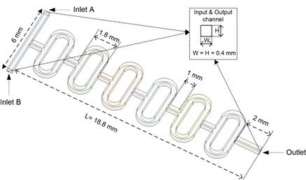
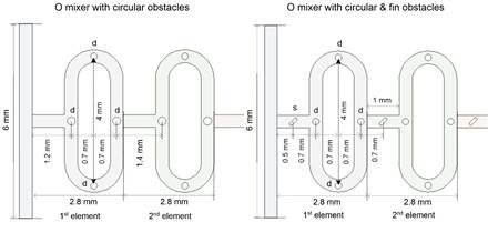
To enhance the mixing performance, circular-shaped obstacles and a combination of circular & cylindrical fin-shaped obstacles are placed inside the O mixer. The diameter of the circular-shaped obstacle (d) is 0.2 mm. The length and width of the cylindrical fin obstacle (s) are 0.3 mm and 0.07 mm, respectively. All examined mixers consist of 6 identical elements connected one after another and the total length is 18.8 mm (one element is 2.8mm long). The detailed configuration of the obstacles in the O mixer is represented in Figure 2.
3. Numerical Setup and Methodology
The fluid behavior was studied using the ANSYS Fluent 15 commercial CED software. The fluid is considered incompressible, with steady-state, isothermal, and laminar flow conditions. The following advection-diffusion, Navier-Stokes, and continuity equations are used to solve the flow field: [42-43]


Where V is the fluid velocity (m/sec), ρ is the fluid density (Kg/m3), P is the fluid pressure (Pa), μ is the fluid viscosity ![]() ,
, ![]() is the fluid molar concentration (mol/m3), and D is fluid diffusivity (m2/sec).
is the fluid molar concentration (mol/m3), and D is fluid diffusivity (m2/sec).
The output of the mixer channel was set to zero (0) gauge pressure, the uniform flow velocity was used at both inlets (Inlet A and Inlet B), and the no-slip velocity condition was taken into account at walls for the numerical simulation. Relative species concentrations of fluids are assumed to be one (1) for inlet A and zero (0) for inlet B. The two input fluids are assumed to have the same density ρ=998.2 Kg/m3, same dynamics viscosity μ=0.001 Pa s and diffusivity D=1× -9 m2/s [5]. The method known as SIMPLE (Semi Implicit Method for Pressure Equations) is utilized to solve the pressure-velocity coupling [7]. On the other hand, momentum and species concentration are handled using a second-order upwind strategy. In addition, scaled residuals of 1× 10⁻⁶ are utilized to apply the convergence requirements for continuity, momentum, and species transport equations. Reynolds number is a crucial dimensionless parameter that is calculated by the following equation [44].

Where Re is the Reynolds number, d is the characteristics hydraulic diameter (m), W is the width of the mixing channel (m) and H is the height of the mixing channel (m). The mixing index is calculated using the following equations [45]

Where, Ci is the concentration at the ith node, Cav is the average concentration, σ is the standard deviation, and σmax is the maximum standard deviation (σmax=0.5). Maximum and minimum efficiency can be zero (η=0) and one (η=1), respectively.
Mixing efficiency and pressure drop alone is not sufficient to have a complete comparison among various mixers. Hence, the mixing cost is computed by using pumping power which is used to flow liquid inside the mixer by following the equation [12-13].
Where MC denotes the mixing cost (Watt), ∆P is the pressure drops (Pa), Q is the flow rate (m3/s).
3. 1. Mesh Independency
Grid independence tests were conducted to determine an appropriate number of grids because the numerical results are always dependent on the mesh system. Fluent 15 was used to generate the structured grids with hexahedral elements for all mixers. An illustration of the O mixer with circular and fin obstacles is shown in Figure 3.
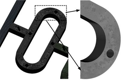
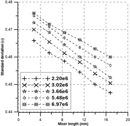
The grid dependency of the O mixer with fin and circular obstacles is displayed in Figure 4 for five distinct nodes ranging from 2.20×10⁶ to 6.97×10⁶. Along the mixer's axial length, the standard deviation of fluid mixing was computed at Re=50. As the number of grids rises the standard deviation increases as indicated by Figure 4. The difference in standard deviation between nodes 5.48×10⁶ and 6.97×10⁶ is small. Thus, to obtain acceptable numerical data at a reasonable cost, 5.48×10⁶ nodes are utilized for simulation. Similarly, for the O mixer and the O mixer with circular obstacles, 5.41×10⁶ nodes and 5.43×10⁶ nodes of mesh were employed, respectively.
3. 2. Numerical Validation
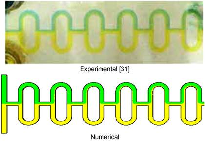
The numerical data obtained in this work is compared with published experimental results by M. Nimafar et al. [31] to verify the numerical setup. The top view of the fluid mixing concentration for the experimental test and computational model used in this study is demonstrated in Figure 5 at a Reynolds number of 4.166. Blue and yellow colors indicate two input fluids and two fluids mixed along the channel. The numerical finding, which is consistent with the experimental value, indicates poor species mixing.
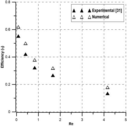
As shown in Figure 6, a qualitative comparison is made between the numerical mixing index and the published experimental result [31] of the O micromixer without any obstacles. The maximum difference between experimental and numerical values is less than 20%. There are two potential causes for the disparity. First off, the computational model and the experimental prototypes utilized by M. Nimafar et al. [31] may differ in dimension and smoothness. Secondly, the numerical mixing efficiency is larger than the experimental values, which can be explained by the fact that the experimental efficiency was calculated using top-view images, whereas the numerical data was computed at the cross-sections of the channel.
4. Result and Discussion
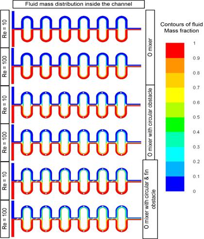
The mixing index of the three mixers was computed numerically for Reynolds numbers ranging from 1 to 100. The numerical mixing efficiency obtained for all three mixers is presented in Figure 7 and water distribution along the channel is illustrated in Figure 8. All mixers show an efficiency of more than 50% at Re ≤1. At low Reynolds numbers (Re ≤1), molecular diffusion dominant the mixing process, and fluids have longer residence times resulting in high mixing efficiency. For channels with micromixers, at moderate Reynolds numbers (1<Re ≤10), fluids have less time to mix resulting poor efficiency as evident in Figure 7 and Figure 8. Efficiency starts to increase as the Reynolds numbers increase (Re>10). In this case, the mixing time decreases with the increase of Reynolds numbers (flow rate), but the fluids path becomes longer due to the split and recombination of fluids which compensates for the shorter mixing time as shown in Figure 8. This effect is more evident in the case of the O mixer with circular & find obstacles and mixing efficiency is the highest (about 50%). Whereas the efficiency is about 15% and 20% for the O mixer and the O mixer with circular obstacles at Re=100, respectively. In addition, the O mixer with circular & fin obstacles yields three times more efficiency than the other two at all examined Reynolds numbers.
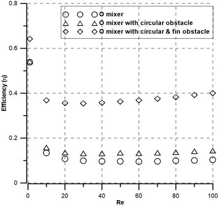
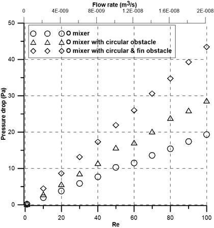
Figure 9 presents the relationship between pressure drop, flow rate, and Reynolds numbers for all three mixers. Pressure drop increases with the increase of corresponding Reynolds numbers and flow rates. The O mixer shows the lowest pressure drop due to a lack of barriers and the O mixer with circular & fin obstacles produces the highest pressure drop. The O mixer with circular obstacles has a 1.5 times higher pressure drop than the O mixer but a 1.5 times lower pressure drop than the O mixer with circular & fin obstacles at Re=100.
Mixing efficiency and pressure drop alone is not sufficient to suggest the best-performing mixer. Therefore, a parameter called mixing cost is evaluated and presented in Figure 10. The O mixer with circular obstacles shows the highest mixing cost. Whereas the mixing cost of the O mixer with circular & fin obstacles is the lowest despite the presence of the obstacles. Therefore, the O mixer with circular & fin obstacles is the best-performing mixer with the highest mixing efficacy and the lowest mixing cost.
6. Conclusion
In this study, two types of obstacles (circular obstacles and circular & fin obstacles) are introduced to a planar O mixer. Numerical simulation was performed to evaluate the effect of obstacles on fluid flow, mixing performance, and pressure drop using the ANSYS 15 commercial software at a wide range of Reynolds numbers (1≤Re ≤100). The numerical results showed good agreement with the experimental and present good mixing performance over a wide range of flow conditions, particularly in the low Re (Re=1) and high Re (Re=100). The presented design is planar, and obstructions are all full channel height, thus can be constructed in a simple fabrication process. The introduction of circular and fin obstacles inside the O mixer increases the efficacy three times compared to the O mixer without obstacles, and a maximum of 50% efficiency can be achieved with only six elements. Efficiency also increases with the increase of elements for all three mixers. Desire efficiency can be obtained by adding elements in series. Though the pressure drop of the O mixer with circular and find obstacles is high, the mixing cost is the lowest due to its high efficacy. Finally, it can be proposed that the O micromixer with circular and fin obstacles is the best performing one which can be easily realized and integrated with microfluidic systems due to the simple planar structure.
References
[1] J. Rahmannezhad and S. A. Mirbozorgi, "CFD analysis and RSM-based design optimization of novel grooved micromixers with obstructions," Int. J. Heat Mass Transf., vol. 140, pp. 483-497, 2019. doi: 10.1016/j.ijheatmasstransfer.2019.05.107. View Article
[2] J. T. Adeosun and A. Lawal, "Numerical and experimental studies of mixing characteristics in a T-junction microchannel using residence-time distribution," Chem. Eng. Sci., vol. 64, no. 10, pp. 2422-2432, 2009. doi: 10.1016/j.ces.2009.02.013. View Article
[3] I. Shah, S. W. Kim, K. Kim, Y. H. Doh, and K. H. Choi, "Experimental and numerical analysis of Y-shaped split and recombination micro-mixer with different mixing units," Chem. Eng. J., vol. 358, pp. 691-706, 2019. doi: 10.1016/j.cej.2018.09.045. View Article
[4] M. Engler, N. Kockmann, T. Kiefer, and P. Woias, "Numerical and experimental investigations on liquid mixing in static micromixers," Chem. Eng. J., vol. 101, no. 1-3, pp. 315-322, 2004. doi: 10.1016/j.cej.2003.10.017. View Article
[5] T. Schikarski, H. Trzenschiok, W. Peukert, and M. Avila, "Inflow boundary conditions determine T-mixer efficiency," React. Chem. Eng., vol. 4, no. 3, pp. 559-568, 2019. doi: 10.1039/c8re00208h. View Article
[6] X. Shi, S. Huang, L. Wang, and F. Li, "Numerical analysis of passive micromixer with novel obstacle design," Journal of Dispersion Science and Technology, vol. 42, no. 3, pp. 440-456, 2019. doi: 10.1080/01932691.2019.1699428. View Article
[7] N. A. Mouheb, D. Malsch, A. Montillet, C. Solliec, and T. Henkel, "Numerical and experimental investigations of mixing in T-shaped and cross-shaped micromixers," Chem. Eng. Sci., vol. 68, no. 1, pp. 278-289, 2012. doi: 10.1016/j.ces.2011.09.036. View Article
[8] M. Hoffmann, M. Schlüter, and N. Räbiger, "Experimental investigation of liquid-liquid mixing in T-shaped micro-mixers using μ-LIF and μ-PIV," Chem. Eng. Sci., vol. 61, no. 9, pp. 2968-2976, 2006. doi: 10.1016/j.ces.2005.11.029. View Article
[9] T. M. Dundi, V. R. K. Raju, and V. P. Chandramohan, "Characterization of mixing in an optimized designed T-T mixer with cylindrical elements," Chinese J. Chem. Eng., vol. 27, no. 10, pp. 2337-2351, 2019. doi: 10.1016/j.cjche.2019.01.030. View Article
[10] S. Wong, M. Ward, and C. Wharton, "Micro T-mixer as a rapid mixing micromixer," Sensors Actuators B Chem., vol. 100, pp. 359-379, 2004. doi:10.1016/J.SNB.2004.02.008. View Article
[11] A. Shamloo, P. Vatankhah, and A. Akbari, "Analyzing mixing quality in a curved centrifugal micromixer through numerical simulation," Chem. Eng. Process. - Process Intensif., vol. 116, pp. 9-16, 2017. doi: 10.1016/j.cep.2017.03.008. View Article
[12] B. Mondal, S. K. Mehta, P. K. Patowari, and S. Pati, "Numerical study of mixing in wavy micromixers: comparison between raccoon and serpentine mixer," Chem. Eng. Process. - Process Intensif., vol. 136, pp. 44-61, 2019. doi: 10.1016/j.cep.2018.12.011. View Article
[13] R. Gidde, "On the study of teardrop shaped split and collision (TS-SAC) micromixers with a balanced and unbalanced split of subchannels," Int. J. Model. Simul., vol. 42, pp. 168-177, 2020. doi: 10.1080/02286203.2020.1858239. View Article
[14] W. Raza, S. Hossain, and K. Y. Kim, "A review of passive micromixers with a comparative analysis," Micromachines, vol. 11, no. 5, 2020. doi: 10.3390/MI11050455. View Article
[15] C. Y. Lee, C. L. Chang, Y. N. Wang, and L. M. Fu, "Microfluidic mixing: A review," Int. J. Mol. Sci., vol. 12, no. 5, pp. 3263-3287, 2011. doi: 10.3390/ijms12053263. View Article
[16] S. M. Saravanakumar and P. V. Cicek, "Microfluidic Mixing: A Physics-Oriented Review," Micromachines, vol. 14, no, 10, 2023, doi.org/10.3390/mi14101827 View Article
[17] G. Cai, L. Xue, H. Zhang, and J. Lin, "A review on micromixers," Micromachines, vol. 8, no. 9, 2017. doi: 10.3390/mi8090274. View Article
[18] N. T. Nguyen and Z. Wu, "Micromixers - A review," J. Micromechanics Microengineering, vol. 15, no. 2, 2005. doi: 10.1088/0960-1317/15/2/R01. View Article
[19] C. Y. Lee, W. T. Wang, C. C. Liu, and L. M. Fu, "Passive mixers in microfluidic systems: A review," Chemical Engineering Journal, vol. 288, pp. 146-160, 2016. doi: 10.1016/j.cej.2015.10.122. View Article
[20] V. M. Barabash, R. S. Abiev, and N. N. Kulov, "Theory and Practice of Mixing: A Review," Theoretical Foundations of Chemical Engineering, vol. 52, no. 4, pp. 473-487, 2018. doi: 10.1134/S004057951804036X. View Article
[21] C. Y. Lee and L. M. Fu, "Recent advances and applications of micromixers," Sensors Actuators, B Chem., vol. 259, pp. 677-702, 2018. doi: 10.1016/j.snb.2017.12.034. View Article
[22] D. Bothe, C. Stemich, and H. Warnecke, "Computation of scales and quality of mixing in a T-shaped microreactor," Computers & Chemical Engineering, vol. 32, pp. 108-114, 2008. doi: 10.1016/j.compchemeng.2007.08.001. View Article
[23] D. Bothe, A. Lojewski, and H. Warnecke, "Fully resolved numerical simulation of reactive mixing in a T-shaped micromixer using parabolized species equations," Chem. Eng. Sci., vol. 66, no. 24, pp. 6424-6440, 2011. doi: 10.1016/j.ces.2011.08.045. View Article
[24] C. Galletti, M. Roudgar, E. Brunazzi, and R. Mauri, "Effect of inlet conditions on the engulfment pattern in a T-shaped micro-mixer," Chem. Eng. J., vol. 185-186, pp. 300-313, 2012. doi: 10.1016/j.cej.2012.01.046. View Article
[25] L. Y. Tseng, A. S. Yang, C. Y. Lee, and C. Y. Hsieh, "CFD-based optimization of a diamond-obstacles inserted micromixer with boundary protrusions," Eng. Appl. Comput. Fluid Mech., vol. 5, no. 2, pp. 210-222, 2011. doi: 10.1080/19942060.2011.11015365. View Article
[26] Y. Fang, Y. Ye, R. Shen, P. Zhu, R. Guo, Y. Hu, and L. Wu, "Mixing enhancement by simple periodic geometric features in microchannels," Chem. Eng. J., vol. 187, pp. 306-310, 2012, doi: 10.1016/j.cej.2012.01.130. View Article
[27] M. A. Ansari, K. Y. Kim, and S. M. Kim, "Numerical and experimental study on mixing performances of simple and vortex micro T-mixers," Micromachines, vol. 9, no. 5, 2018. doi: 10.3390/mi9050204. View Article
[28] H. S. Santana, J. L. Silva, D. S. Tortola, and O. P. Taranto, "Transesterification of sunflower oil in microchannels with circular obstructions," Chinese J. Chem. Eng., vol. 26, no. 4, pp. 852-863, 2018. doi: 10.1016/j.cjche.2017.08.018. View Article
[29] J. L.S. Júnior, V. A. Haddad, O. P. Taranto, and H. S. Santana, "Design and Analysis of New Micromixers Based on Distillation Column Trays," Chem. Eng. Technol., vol. 43, no. 7, pp. 1249-1259, 2020. doi: 10.1002/ceat.201900668. View Article
[30] S. J. Tan, K. H. Yu, M. A. Ismail, and Y. H. Teoh, "Enhanced liquid mixing in T-mixer having staggered fins," Asia-Pacific J. Chem. Eng., vol. 15, no. 6, pp. 1-10, 2020. doi: 10.1002/apj.2538. View Article
[31] M. Nimafar, V. Viktorov, and M. Martinelli, "Experimental Investigation of Split and Recombination Micromixer in Confront with Basic T- and O- type Micromixers," International Journal of Mechanics and Applications, vol. 2, no. 5, pp. 61-69, 2012. doi: 10.5923/j.mechanics.20120205.02. View Article
[32] A. A. S. Bhagat and I. Papautsky, "Enhancing particle dispersion in a passive planar micromixer using rectangular obstacles," J. Micromechanics Microengineering, vol. 18, no. 8, p. 085005, 2008. doi: 10.1088/0960-1317/18/8/085005. View Article
[33] V. Mengeaud, J. Josserand, and H. H. Girault, "Mixing Processes in a Zigzag Microchannel: Finite Element Simulations and Optical Study," Anal. Chem., vol. 74, no. 16, pp. 4279-4286, 2002. doi: 10.1021/AC025642E. View Article
[34] T. R. Shih and C. K. Chung, "A high-efficiency planar micromixer with convection and diffusion mixing over a wide Reynolds number range," Microfluid. Nanofluidics, vol. 5, no. 2, pp. 175-183, 2007. doi: 10.1007/S10404-007-0238-4. View Article
[35] A. A. S. Bhagat, E. T. K. Peterson, and I. Papautsky, "A passive planar micromixer with obstructions for mixing at low Reynolds numbers," J. Micromechanics Microengineering, vol. 17, no. 5, p. 1017, 2007. doi: 10.1088/0960-1317/17/5/023. View Article
[36] J. S. Shim, I. Nikcevic, M. J. Rust, A. A. S. Bhagat, W. R. Heineman, C. J. Seliskar, C. H. Ahn, and I. Papautsky, "Simple passive micromixer using recombinant multiple flow streams," Microfluidics, BioMEMS, and Medical Microsystems V, vol. 6465, p. 64650Y, 2007. doi: 10.1117/12.701977. View Article
[37] C. K. Chung and T. R. Shih, "Effect of geometry on fluid mixing of the rhombic micromixers," Microfluid. Nanofluidics, vol. 4, no. 5, pp. 419-425, 2007. doi: 10.1007/S10404-007-0197-9. View Article
[38] R. H. Liu, M. A. Stremler, K. V. Sharp, M. G. Olsen, J. G. Santiago, R. J. Adrian, H. Aref, and D. J. Beebe, "Passive mixing in a three-dimensional serpentine microchannel," J. Microelectromechanical Syst., vol. 9, no. 2, pp. 190-197, 2000. doi: 10.1109/84.846699. View Article
[39] S. Yuan, M. Zhou, T. Peng, Q. Li, and F. Jiang, "An investigation of chaotic mixing behavior in a planar microfluidic mixer," Phys. Fluids, vol. 34, no. 3, 2022. doi: 10.1063/5.0082831. View Article
[40] S. H. Wong, P. Bryant, M. Ward, and C. Wharton, "Investigation of mixing in a cross-shaped micromixer with static mixing elements for reaction kinetics studies," Sensors Actuators B Chem., vol. 95, no. 1-3, pp. 414-424, 2003. doi: 10.1016/S0925-4005(03)00447-7. View Article
[41] A. D. Stroock, S. K. W. Dertinger, A. Ajdari, I. Mezić, H. A. Stone, and G. M. Whitesides, "Chaotic mixer for microchannels," Science, vol. 295, no. 5555, pp. 647-651, 2002. doi: 10.1126/science.1066238. View Article
[42] A. Mariotti, C. Galletti, R. Mauri, M. V. Salvetti, and E. Brunazzi, "Steady and unsteady regimes in a T-shaped micro-mixer: Synergic experimental and numerical investigation," Chem. Eng. J., vol. 341, pp. 414-431, 2018. doi: 10.1016/j.cej.2018.01.108. View Article
[43] C. A. Cortes-Quiroz, A. Azarbadegan, and M. Zangeneh, "Effect of channel aspect ratio of 3-D T-mixer on flow patterns and convective mixing for a wide range of Reynolds number," Sensors Actuators, B Chem., vol. 239, pp. 1153-1176, 2017. doi: 10.1016/j.snb.2016.08.116. View Article
[44] G. Orsi, M. Roudgar, E. Brunazzi, C. Galletti, and R. Mauri, "Water-ethanol mixing in T-shaped microdevices," Chem. Eng. Sci., vol. 95, pp. 174-183, 2013. doi: 10.1016/j.ces.2013.03.015. View Article
[45] M. M. Mahmud, S. Hossain and J. H. Kim, "A SAR Micromixer for Water-Water Mixing: Design, Optimization, and Analysis," processes, vol. 9, 2021. doi.org/10.3390/pr9111926 View Article