Journal of Fluid Flow, Heat and Mass Transfer (JFFHMT)
ISSN: 2368-6111

Volume 12 - Year 2025 - Pages 447-456
DOI: 10.11159/jffhmt.2025.045
Systematic Assessment of Turbulence–Chemistry Interaction for Partially- Premixed Acetylene/Air Flames
Christian Herwerth1,2, Michael Pfreuntner1, Hannah Kaiser2, Herbert Pfeifer2
1Linde GmbH
Carl-von-Linde-Strasse 25, 85716 Unterschleissheim, Germany
christian.herwerth@linde.com
2RWTH Aachen University, Aachen, Germany, Faculty of Georesources and Materials
Engineering, Department for Industrial Furnaces and Heat Engineering
Abstract - To validate a CFD modeling approach for the assessment of the combustion efficiency in partially premixed acetylene/air flames, this study integrates experimental and numerical methods to investigate flame structure, flow field characteristics, and heat transfer behaviour. Measurements of the global heat flux and stagnation pressure, alongside OH* chemiluminescence imaging, are employed to analyse the primary and secondary oxidation front of flames with high heat release rates in the primary oxidation. The experimental setup includes a water-cooled calorimeter with a capillary bore for static pressure extraction and a UV-sensitive camera with a bandpass filter to capture averaged OH* intensity. These results are compared to CFD simulations using the Flamelet-Generated-Manifold (FGM) and Reynolds-Stress-Model (RSM) frameworks. While the experimentally determined combustion efficiency is reproduced sufficiently for practical applications, the CFD model fails to predict the characteristic heat transfer maximum observed at a firing rate/Reynolds number specific torch-to-target distance. Conversely, the stagnation pressure is accurately captured across all flame configurations. The OH* imaging reveals flame quenching near the flame/wall interface at low burner-to-target distances, attributed to curvature-induced strain and cold wall effects—phenomena not adequately represented in the current CFD model. These discrepancies significantly impact the heat transfer predictions, specifically for low torch-to-target distances with an impinged primary reaction front. Future work should incorporate diffusion flamelets rather than premixed flamelets to explore their sensitivity to strain and scalar dissipation rates to enhance the fidelity of heat transfer modelling in similar flame impingement systems.
Keywords: Experimental heat transfer, numerical heat transfer, partially- premixed combustion, turbulent impinging flame jets, turbulence-chemistry-interaction, Flamelet-Generated-Manifold, Reynolds-Stress-Model, Stagnation Pressure, OH* chemiluminescence, Flame Quenching and Extinction
© Copyright 2025 Authors - This is an Open Access article published under the Creative Commons Attribution License terms Creative Commons Attribution License terms. Unrestricted use, distribution, and reproduction in any medium are permitted, provided the original work is properly cited.
Date Received: 2025-06-10
Date Revised: 2025-10-06
Date Accepted: 2025-11-25
Date Published: 2025-12-16
1. Introduction
Direct flame impingement (DFI) is commonly used to reheat structural steel components during manufacturing processes [1]. In configurations where the impingement zone is not enclosed within a furnace atmosphere, radiative heat transfer from the surrounding gas and walls typically becomes negligible, and convective mechanisms dominate [2]. The experimental investigation of DFI systems has been extensively documented and summarized in various reviews [3], [4]. More recently, numerical methods have gained increasing attention. Due to the complexity of flame/wall interactions- critical for understanding both heat transfer and pollutant formation- academic studies often rely on scale- and time-resolving approaches such as Large Eddy Simulation (LES) and Direct Numerical Simulation (DNS) [5], [6], [7]. While these methods offer high accuracy, they remain computationally intensive and are often impractical for the design and optimization of industrial DFI systems.
To address this challenge, and with the objective of verifying a RANS-based setup suitable for industrial applications, recent research efforts demonstrate the applicability of ω-based turbulence models (SST k-ω and Reynolds-Stress-Model, RSM) in combination with the Flamelet-Generated-Manifold (FGM) reduction [8]. The approach is used to predict the global heat transfer between a circular flame jet and a water-cooled target rather well when compared to ε-based turbulence models [8] , [9]. However, these previous research results suggest some inaccuracies regarding the heat transfer prediction, especially for low torch/target distances. Due to the inherent complexity of turbulence–chemistry interaction (TCI) in turbulent flames, the numerical setup and the computed reaction zones and heat release rate (HRR) are therefore considered critical. The stagnation pressure as an easy-to-measure parameter is directly dependent on the density, velocity and temperature fields as well as the species distributions and can therefore serve as high level metric on the quality of the TCI description as it combines several relevant parameters. Additionally, OH* intensity measurements can provide further information about the reactive flow field. The OH radical, and particularly its excited state OH*, plays a key role in hydrocarbon and hydrogen combustion. As part of the chain reaction sustaining the exothermal process, OH* serves as a reliable flame marker and indicator of the flame front [10]. Several studies confirm a strong correlation between OH* distribution and HRR across various flame configurations [11], [12]. The visualization of the OH* radical is achieved by measuring its chemiluminescent intensity near 307 nm, making it a valuable tool for analyzing reaction zones, spatial HRR, and ultimately for assessing TCI in CFD models. Especially true, for flames of high heat release rates within the primary oxidation front such as partially-premixed acetylene/air flames, the HRR alone does not suffice to assess the flame structure in its entirety. A better CFD-based variable for the assessment of both reaction fronts is the product formation rate- the source term for the progress variable in reduced order reaction modeling such as the FGM approach [13]. To achieve an understanding with respect to the TCI in the system and its numerical description, the subsequent documentation is dedicated to a multi-method approach to uncover the deviation between the numerically and experimentally derived combustion efficiency by a systematic verification of the CFD model used to model the heat transfer between a flame and a target.
2. Related Work
The following sections summarize the relevant preliminary research efforts and their findings to provide context for the interpretation of the results. The summary includes a description of the experimental setups used to measure the heat transfer in partially- premixed acetylene/air flame impingement systems, as well as a description of the CFD model utilized to derive the flame structure and to compute the heat transfer between the flame and the target [8], [9]. As it plays a pivotal role in the evaluation of the turbulence–chemistry interaction, and its numerical prediction, the methodology for capturing and processing the OH* intensity distributions is also described [10].
2. 1. Experimental assessment of the combustion efficiency
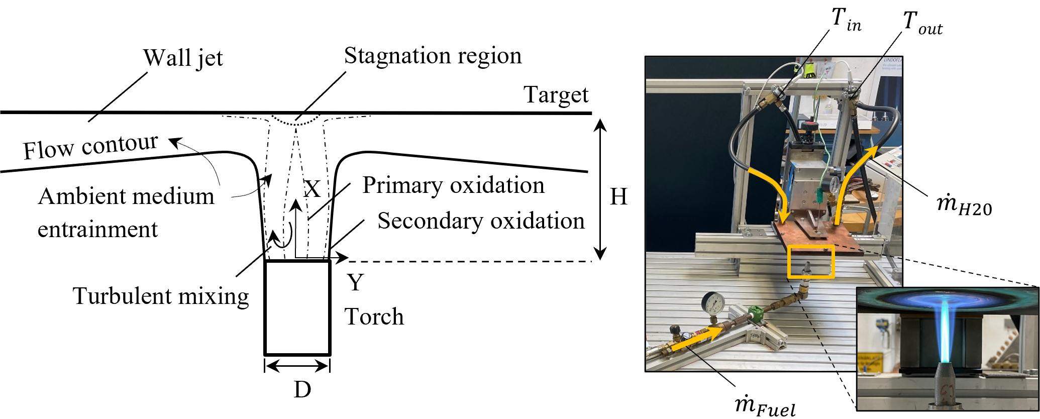
The experimental setup to assess the heat transfer efficiency/combustion efficiency as described in more detail by reference [9] uses a water-cooled calorimeter to evaluate the global heat transfer between a partially- premixed acetylene/air flame. Measuring the fuel gas and water flow rates as well as the in- and outlet temperatures of the coolant allows the computation of the combustion efficiency. The experiments determine the influence of the Reynolds number/firing rate and the torch-to-target distance on the heat transfer efficiency. The results of the study show good agreement with existing literature and confirm the setups' suitability for evaluating industrial flame heating processes and enhancement strategies [9]. Figure 1 shows the aerodynamic principles of DFI systems as well as a depiction of the test setup.
2. 2. Numerical study on the computation of the combustion efficiency
A numerical study described in greater detail in reference [8] investigates the influence of the turbulence model on the computation of the heat transfer efficiency in DFI systems. Various turbulence models are evaluated, including k-ε variants, the SST k-ω, and the stress-ω Reynolds-Stress Model (RSM), alongside a Flamelet-Generated-Manifold (FGM) combustion model. Validation against the preliminary experimental data of reference [9] shows that ε-based models significantly underpredict the heat transfer/combustion efficiency, while the SST k-ω and the ω-based RSM models offer better agreement. Radiation was found to have negligible impact under ambient conditions, eliminating this mechanism as a target of further investigations on the also documented deviations between the numerically and experimentally determined combustion efficiency. The study highlights the importance of TCI modelling and recommends the SST k-ω and the RSM for further optimization and design tasks. The noted deviations between the characteristic combustion efficiency as a function of the normalized torch/target distance H/D reveals the importance of further efforts to assess the computation of the TCI in the respective numerical model and to determine effects responsible for the observed deviations for low torch/target distances [8].
2. 3. Investigations on the flame structure and TCI verification
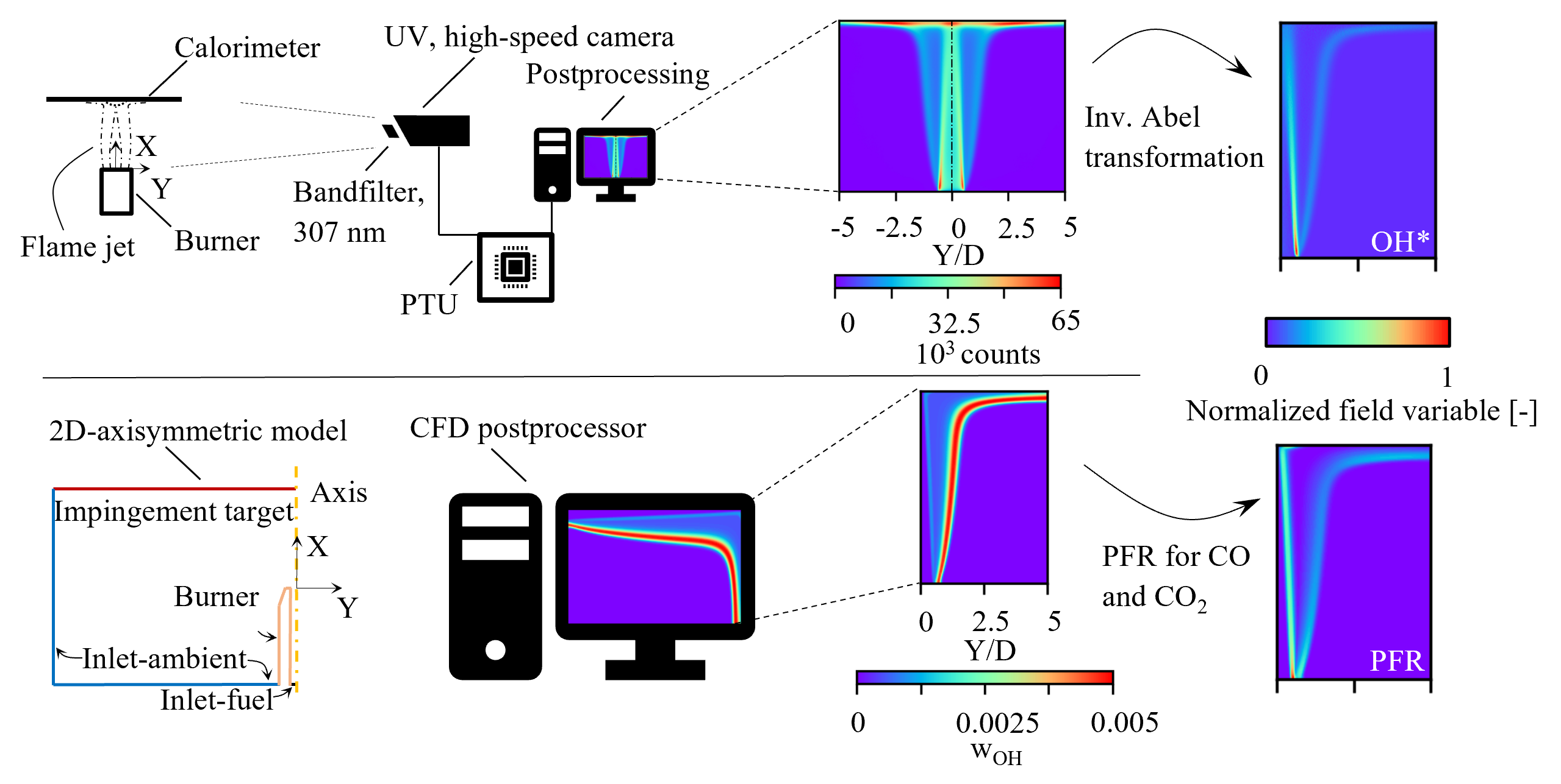
To address the remaining uncertainty about the numerical TCI description for the investigated partially- premixed, turbulent DFI systems, the visualization of OH* chemiluminescence in reference [13] investigates the flame structure and reaction zones for various flame configurations and torch-to-target distances. The inverse Abel transformation is employed to align the experimental line-of-sight images and the numerical results taken from a 2D-axisymmetric RANS setup (ω-based RSM with FGM reduction). The methods are visualized in figure 2. When compared to the experimental OH* intensity data, the numerical data shows good agreement between the flame structure and the predictions of (HRR) and especially the product formation rate (PFR) of CO and CO2 to also evaluate the secondary reaction front. The results show that while HRR correlates well with the OH* intensity in the primary oxidation zone, the PFR provides a better indicator for both reaction fronts. The study highlights the importance of PFR and HRR in assessing turbulence–chemistry interaction and flame structure and identifies discrepancies in the wall jet region as a key area for future research [13].
3. Methods
Employing the methods and considering the results of the literature summarized in chapter 2, the subsequent paragraphs describe the comparison of the numerical modelling with the corresponding experimental investigations to finally and fully assess the sufficiency of the numerical model and to emphasize the potential shortcomings, that influence the computed results. An additional method to measure the stagnation pressure as an indicator for the coupling between mass transfer phenomena and the temperature dependent density field is introduced additionally.
3.1. Experimentally and numerically derived heat transfer
Table 1 lists the experimental dataset for the investigation of three flames of different Reynolds number and firing rates using the facility describes in reference [9] (figure 1). The Reynolds numbers are taken from reference [8] and [13]. The flame Re=6000 is inspired by actual DFI application settings, the flames Re=2825 and Re=9100 frame the stability limits of the utilized burner. Table 2 contains the corresponding flow configurations using the numerical model description (FGM, ω-based RSM) from reference [8] (figure 2).
Table 1: Investigated flow configurations and firing rates for the experiment.
|
Reynolds-number [-] |
|
|
Power [kW] |
|
2825 |
1.83 · 10-5 |
1.16 · 10-4 |
≈ 1.04 |
|
6000 |
3.88 · 10-5 |
2.45 · 10-5 |
≈ 2.20 |
|
9100 |
5.93 · 10-5 |
3.73 · 10-5 |
≈ 3.37 |
*: Taken at 273.15 K and 101.3 kPa
Table 2: Investigated flow configurations for the numerical model. Firing rates according to table 1
|
Reynolds-number [-] |
|
f [-] |
|
2825 |
1.7077 · 10-4 |
0.12638 |
|
6000 |
3.6061 · 10-4 |
0.12677 |
|
9100 |
55.045 · 10-4 |
0.12689 |
3.2. Stagnation pressure measurements
As suggested by the results for all considered flames in reference [13], the PFR and the HRR is predicted reasonably well, especially for the primary and most significant reaction front that drives the heat flux and therefore the combustion efficiency. Based on this finding one may infer, that other fields related to the HRR and PFR are computed sufficiently as well. To evaluate this hypothesis, two additional fields, particularly descriptive and relevant for the convective heat transfer and the assessment of the numerical TCI prediction within the flame are the temperature and velocity field v. The stagnation pressure ps connects both field through its dependency on the velocity and the temperature T and composition dependent density field ρ (equation 1). For reduced-order chemistry descriptions, the composition of the flow field is described in terms of the mixture fraction f and progress variable c [14].
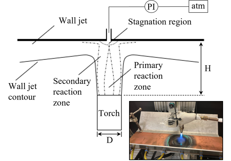
Together with the OH* visualization, the stagnation pressure distribution within the stagnation zone can provide further information about the interaction between the mass transport and the chemistry model and ultimately about the TCI. It is measured using an experimental facility inspired by Lin and Eagar’s setup [15]: The flame jet is impinging on a water-cooled copper plate with a 0.4 mm central bore connected to a differential pressure indicator (Distributor: EFE, Type: PHE167; 0 – 50000 Pa ± 0.047 % FS). Figure 3 visualizes the schematic of the setup in which the torch moves in a rectangular pattern of equidistant step size (0.5 mm) to capture the spatial distribution of the pressure field. Each recorded reading consists of 500 values taken within 0.1 s after a delay time of 1 s to allow for flow stabilization. Bore diameter, step size, delay time and sample size were investigated beforehand to ensure the independence of the reading with respect to these parameters.
3.2. OH* intensity visualization
Further investigating the uncovered deviation between the numerically and experimentally derived combustion efficiency (chapter 4.1.) the method for the visualization of OH* chemiluminescence of reference [13] is employed (figure 2). The flame configurations from tables 1 and 2 are considered for the comparison between the experiment and the numerical results. The variables for the comparison are the computed PFR and the OH* intensity as they provide a good comparability for flames with high heat release rate in the primary reaction such as acetylene [13].
4. Results
The subsequent chapters provide an overview of the results. Initially, the results for the numerically and experimentally derived heat transfer/combustion efficiencies are documented and explained. As systematic deviations are observed for this variable, the additional results for the stagnation pressure measurements and the OH* intensity visualization are used to explain and investigate the origin of these differences. Convergence was defined by steady species distributions for the stochiometric components, the heat flow into the target and the product formation rates for CO and CO2 throughout the domain in combination with 10-3 for mass continuity, turbulence and combustion parameters and 10-6 for energy preservation. However, in case the residuals for the mass continuity were not achieved, convergence was also assumed if all other described criteria were met.
4.1. Comparison of experimentally and numerically derived heat transfer
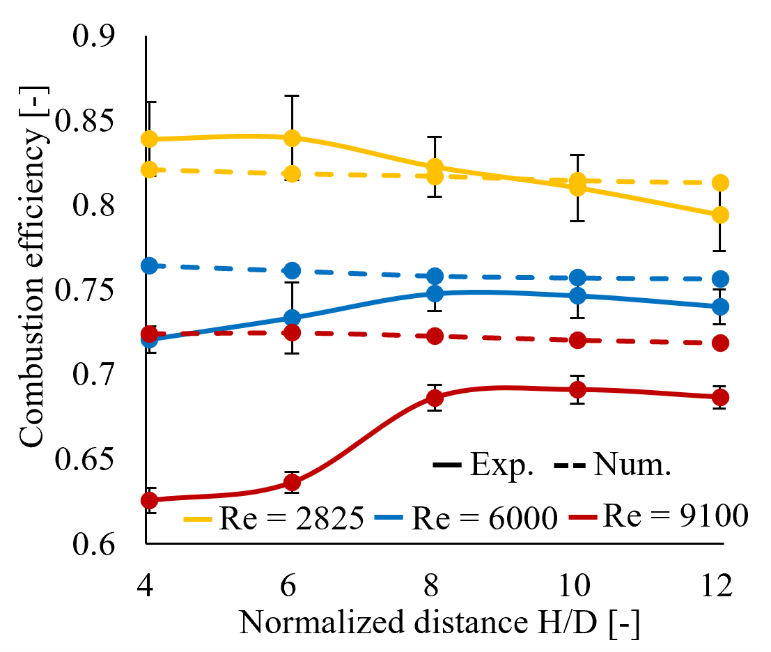
Figure 4 visualizes the comparison between the computed and the measured heat transfer/combustion efficiency of the system acc. table 1 and 2. For the flames of higher Reynolds-number/firing rate, the previously reported clearly distinguishable optimal distance between the torch and the target is observed [16]. For the flame of Re=2825, the optimum is likely found for H/D<4 and therefore not included in the graph. At further distances, past the peak combustion efficiency, the heat transfer drops for all flame configurations. When compared to the heat transfer predictions made employing ε-based turbulence models, where large deviations occur, the numerical value matches the experimental result reasonably well and provide practical relevance of the model. Especially for H/D values for distances beyond the observed maximum value, the experimentally verified drop in heat transfer efficiency is characteristic for all numerical results, regardless of the configuration. Particularly noteworthy and relevant for the interpretation of this offset later on, is the increasing overprediction of combustion efficiency for an increasing Reynolds-number/firing rate and the deviation for low H/D, before the maximum efficiency is reached for the flame Re=6000 and Re=9100.
4.2. Stagnation pressure measurements
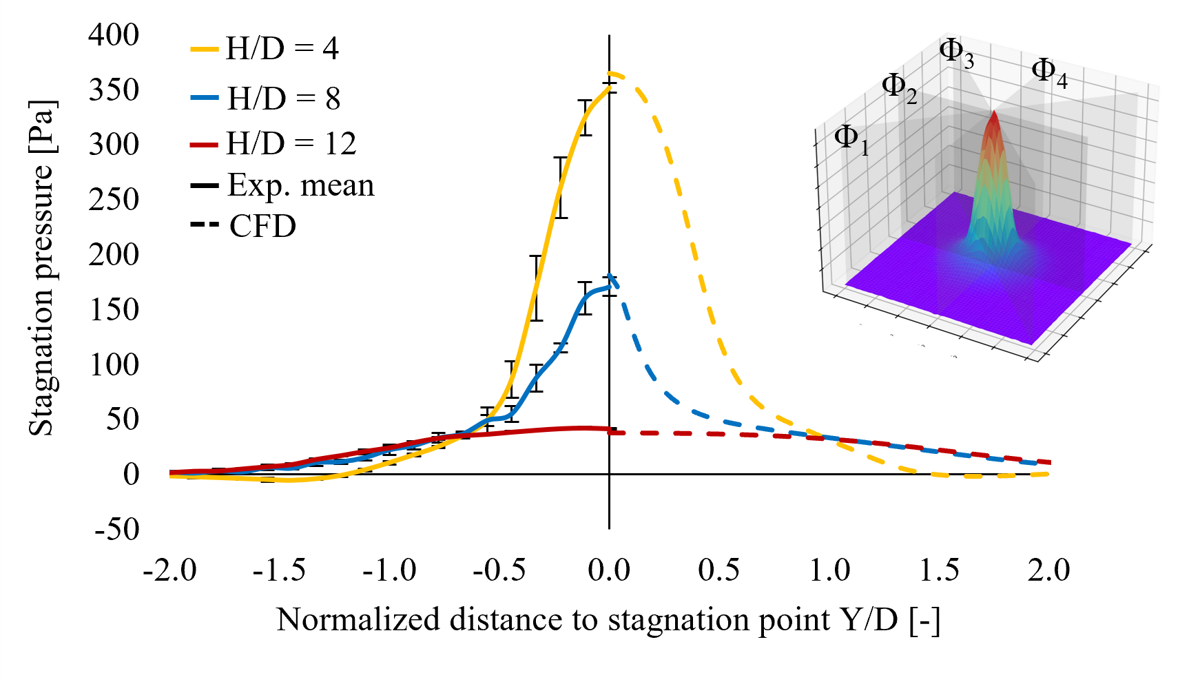
As the heat transfer is dominated by convection, the deviation between the experimental and the numerical combustion efficiency is likely driven by one of the fields directly related to the convective heat transfer- either by the temperature or the velocity field or some basic dependencies of these fields (compare equation 1). Consequently, the stagnation pressure may serve as an indication for the quality of the computation of one or more parameters/fields due to a potentially incorrect TCI model. Figure 5 depicts the result of the stagnation pressure measurements for the flame of Re=6000 for three different torch/target distances. While minor deviations are present, the numerically derived stagnation pressure is in good accordance with the experimental values. The experimental mean is calculated for four individual planes Φ1 - Φ4 (figure 4). The error bars are the corresponding standard deviation. Based on equation 1, the results also suggest a good prediction for the (axial) velocity and a good resemblance of the density field and its influencing parameters. The temperature-dependence is largely driven by the computation of the heat release rate within the flame. The species distribution is determined by an accurate description of the mixture fraction and the progress variable. Due to the accurate match between the numerically derived stagnation pressure distribution with the experimental one, the investigation does not yet allow a conclusion to explain the deviation in terms of the predicted heat transfer characteristics as depicted in figure 4. On the contrary, it suggests an accurate resemblance of at least the free jet and its transition by the proposed CFD model necessitating additional means of investigating the TCI. The results for Re=2825 and Re=9100 are of equally good quality.
4.3. OH* visualization and numerically derived reaction fronts
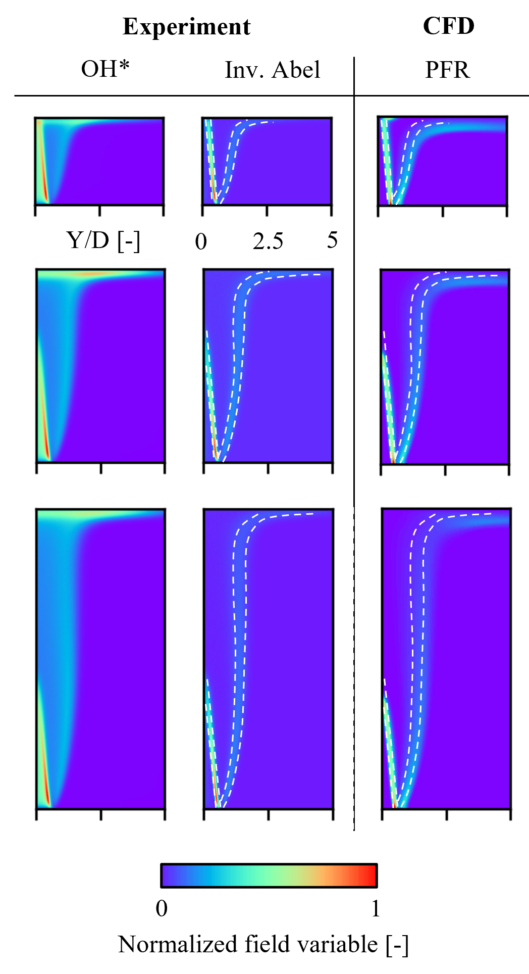
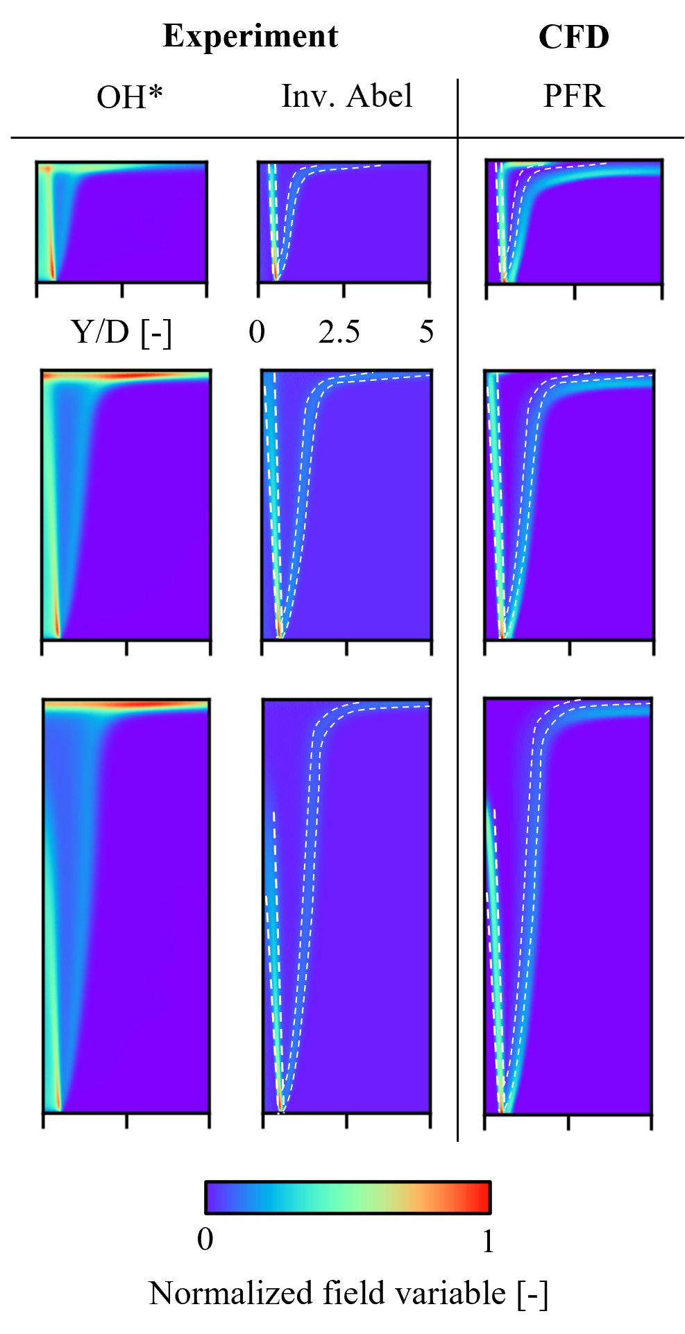
As the stagnation pressure measurements proves the computation of density and velocity fields in the free jet region to be accurate, the OH* intensity imaging method in the search for the deviation of the combustion efficiencies indeed delivers a possible explanation for the described deviations at low H/D values and for the increasing overprediction of combustion efficiency for flames of high firing rate. Figures 6 – 8 summarize the normalized OH* intensity plots alongside the respective numerical analyses (normalized PFR).
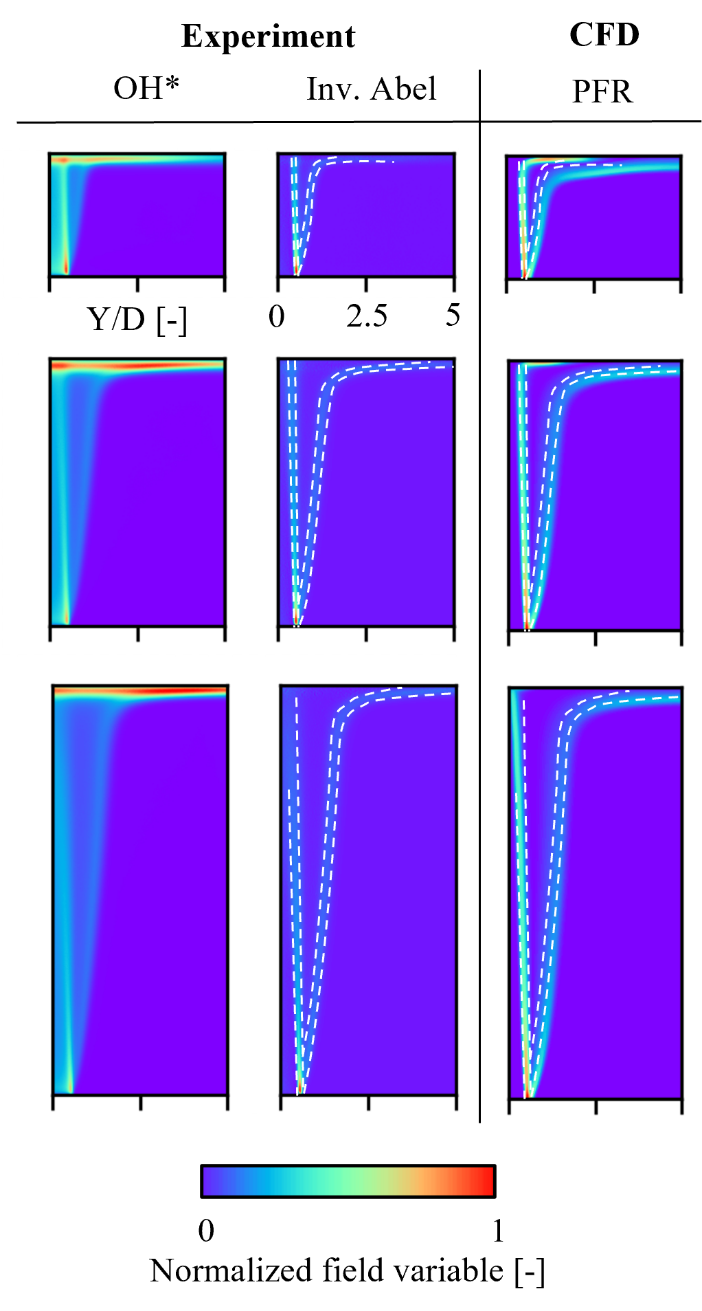
As previously described, the PFR correlates well with the OH* intensity for the primary and the secondary reaction fronts. Based on the released heat of combustion featured by these reactions, the HRR can also be thought of as predicted well. Especially in the free jet, the reaction front and therefore the species and temperature distribution are likely computed properly yielding in an accurate prediction of the stagnation pressure. Various additional conclusions with respect to the predominant species and reactions can be inferred from results [13].
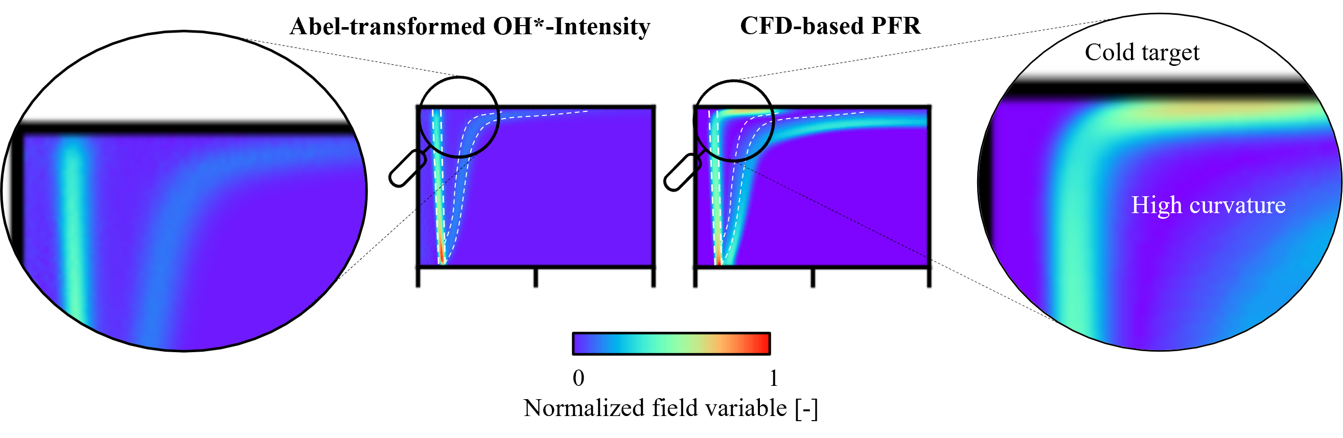
However, taking a closer look at the most relevant region within the DFI system, the flame/wall interface reveals a potential origin of the deviations detected in the heat transfer comparison. Especially for H/D values, where the primary reaction zone impinges on the target and the transition between free jet and wall jet is characterized by high strain rates due to the curvature and the flow deflection from the X- to the Y-direction, the OH* intensity shots reveal a significant deviation. Figure 9 provides the required closer look right at the actual impingement area. While the numerical evaluation predicts a high PFR and the corresponding high correlating OH*-intensity in the wall jet and close to the target, the actual OH* visualization suggest barely any reaction intensity in this area. In order to interpret this contradiction, flame extinction and quenching must be taken into account. Both effects can in theory be captured by the FGM approach by manipulating the computation of the flame speed, the application of flame speed wall damping or the consideration of said effects in the definition of the progress variable [14]. Physically, quenching occurs due to high strain rates within the flame preventing reactants to sufficiently interact with each other due to the rapid removal of relevant species. Another effect responsible for flame quenching can be the presence of a cold target acting as a heat sink limiting endothermal reactions within the complex systems of reactions. Both effects are present in the investigated system (figure 9). Regardless of the actual mechanism, quenching and extinction effects remain difficult phenomena to model but yet prove to have significant relevance for the accurate computation of DFI systems.
4.4. Grid independence
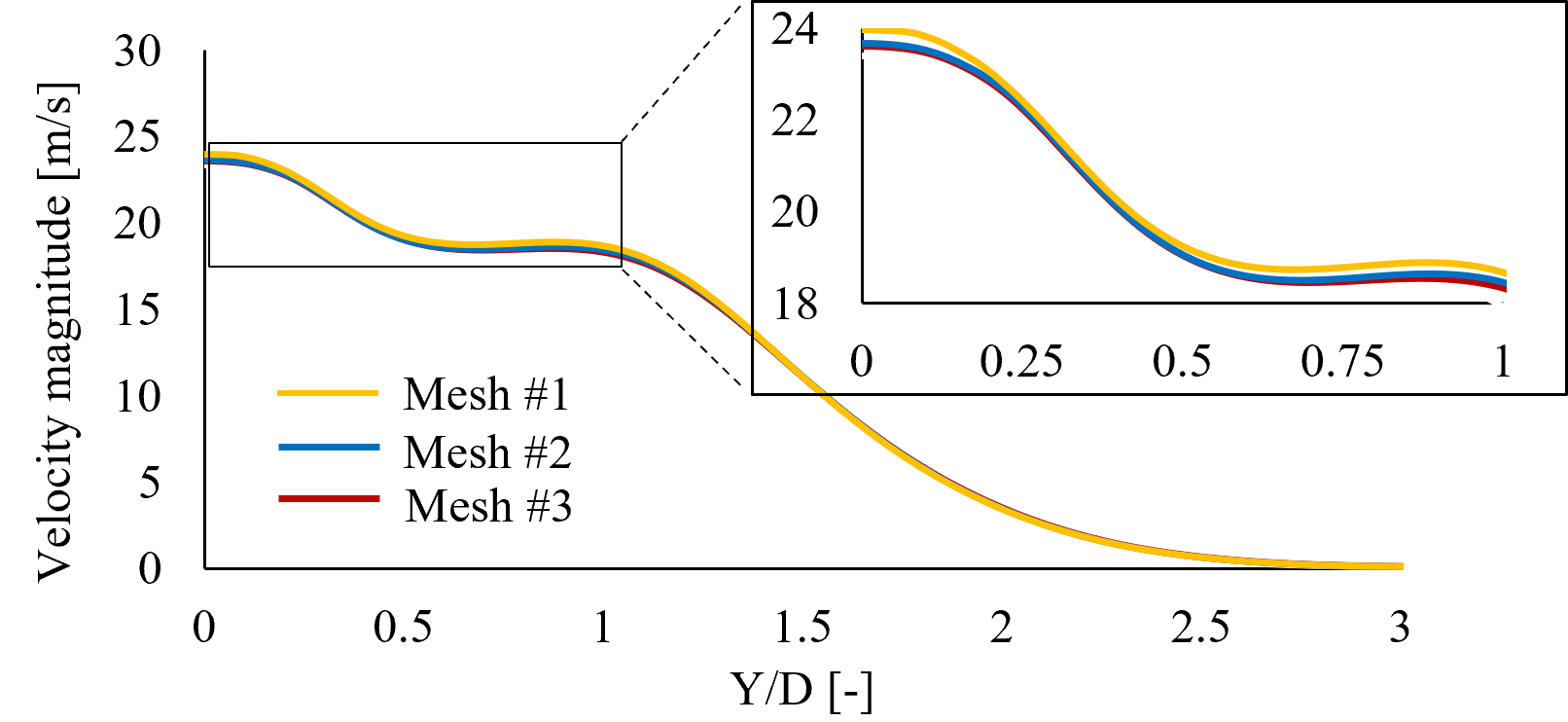
To cover mass flow, turbulence and reaction progress, the verification of the grid independence investigates the gradients of the velocity magnitude, the mean mixture fraction and the turbulent intensity for three meshes with an increasing element count (90, 165, 360 x 103 elements). The configuration H/D = 8 was used and the variables were taken at 85 %, 90 % and 95 % of H/D = 8. While a marginal difference was found for each variable at all distance fractions for the first mesh, mesh #2 and mesh #3 derive similarly resolved functions for the considered variables and for all distance fractions. Figure 10 shows an exemplary result of the independence study. Additionally, the heat flux from the flame into the target was taken as a global variable to assess the mesh independence for the main variable of interest. The difference in global heat flux for mesh #2 and mesh #3 the relative error is less than 1 %, for mesh #1 the deviation is 5 %. Based on the study, the solution is considered independent of the numerical grid. With respect to the results regarding the inadequately resolved flame extinction, all three meshes yield the same result and indicate significant heat release and product formation in the proximity of the target.
5. Discussion
What remains after revealing the lack of flame quenching sensitivity in the numerical model, is a conclusion on the potential effects of this shortcoming especially with respect to the computed combustion efficiency. Impinging jets in general and flame jets in particular are known for high heat transfer coefficients close to the stagnation point [17]. Now flame quenching effects close to stagnation point will cause a significant limitation on the heat release rate, energy density and ultimately in heat transfer efficiency. As higher impingement of the primary reaction front will yield in a higher proportion of the combustion reaction to be quenched, low H/D values will show a higher sensitivity to the lack of the numerical prediction of these effects, so the deviation between the measured and computed combustion efficiency is larger for low H/D values (figure 3). The same is true for flames of high firing rate. A higher firing rate and heat release in the primary reaction will also cause a higher sensitivity to a combustion efficiency reduction due to quenching- an effect also presented in figure 3. Both sensitivities describe the overpredicted combustion efficiency- locally for each flame configuration for low H/D values as well as globally for high Reynolds-numbers and firing rates. Despite the uncovered limitations and with respect to high-fidelity approaches such as LES, which supersede the computational efforts of RANS setups by magnitudes, the CFD model provides a good method for the numerical representation of the DFI system. The stagnation pressure and its corresponding variables are predicted accurately and the PFR rate serves as an appropriate marker for the reaction zones, further confirming the sufficient description of the physical TCI phenomena in most of the jet flame. For the particularly complex but equally relevant flame/wall interactions, additional research is required to capture flame quenching and its effect on the combustion efficiency. As partially- premixed flames employ premixed and diffusion flame regimes, the setup of the FGM requires some assumptions regarding the flamelet type. For this investigation the assumption of “premixed type” flamelets was made. However, further downstream of the primary reaction front, “diffusion-type” flamelets may be a better choice as the oxygen of the premix is spent during the primary oxidation and in the first reaction front. The reaction progress subsequent to the primary oxidation is based on turbulent and diffusive mixing of ambient oxygen into the flame and may be described better by diffusion flamelets. Additionally, for this flamelet definition e. g. FLUENT allows the scalar dissipation rate to be adjusted more directly as to extend the model towards including ignition and extinction effects. The previously touched high-fidelity approach of LES may also be taken into account. However, the computational cost may be extensive compared to the RANS setup even for the 5-equation RSM turbulence model and its extended runtime compared to 2-equation models.
References
[1] G. K. Malikov, D. L. Lobanov, K. Y. Malikov, V. G. Lisienko, R. Viskanta and A. G. Fedorov, "Direct flame impingement heating for rapid thermal materials processing," International Journal of Heat and Mass Transfer, pp. 1751-1758, 2001.View Article
[2] C. E. Baukal, J. Gebhart and B. Gebhart, "A review of empirical flame impingement heat transfer correlations," International Journal of Heat and Fluid Flow, vol. 17, no. 4, pp. 386-396, 1996.View Article
[3] R. Viskanta, "Heat Transfer to Impinging Isothermal Gas and Flame Jets," Experimental Thermal and Fluid Science, pp. 111-134, 1993.View Article
[4] S. Chander and A. Ray, "Flame impingement heat transfer: a review," Energy conversion and management, vol. 46, no. 18-19, pp. 2803-2837, 2005.View Article
[5] P. Pantangi, A. Sadiki, J. Janicka, M. Mann and A. Dreizler, "LES of Premixed Methane Flame Impinging on the Wall Using Non-adiabatic Flamelet Generated Manifold (FGM) approach," Flow, Turbulence and Combustion, vol. 92, pp. 805-836, 2014.View Article
[6] K. Ranga Dinesh, X. Jiang and J. van Oijen, "Direct numerical simulation of hydrogen impinging jet flame using flamelet generated manifold reduction," in Proceedings of the 4th World Hydrogen Technologies Convention 2011, Glasgow, 2011.
[7] A. Gruber, R. Sankaran, E. R. Hawkes and J. H. Chen, "Turbulent flame-wall interaction: a direct numerical study," Journal of Fluid Mechanics, vol. 658, pp. 5-32, 2010.View Article
[8] C. Herwerth, S. Ulmer and H. Pfeifer, "Model development for the heat transfer of an impinging acetylene/air flame to a flat target," in 11th International Conference on Heat Transfer and Fluid Flow, Barcelona, 2024.View Article
[9] C. Herwerth, G. L. Turi da Fonte Dias, J. Ungar, V. Kumbhar, S. Ulmer and H. Pfeifer, "Development of an experimental setup for the practical assessment of partially premixed acetylene/air flame heating processes," in 11th International Conference of Fluid Flow, Heat and Mass Transfer, Toronto, 2024.View Article
[10] J. Warnatz, U. Maas and R. W. Dibble, Combustion- Physical and Chemical Fundamentals, Modeling and Simulation, Experiments, Pollutant Formation, Berlin, Heidelberg: Springer, 2010.
[11] M. Lauer and T. Sattelmayer, "On the Adequacy of Chemiluminescence as a Measure for Heat Release in Turbulent Flames With Mixture Gradients," Journal of Engineering for Gas Turbines and Power, vol. 132, 2010.View Article
[12] Y. Hu, J. Tan, L. Lv and X. Li, "Investigations on quantitative measurement of heat release rate using chemiluminescence in premixed methane-air flames," Acta Astronautica, vol. 164, pp. 277-286, 2019.View Article
[13] C. Herwerth, H. Kaiser and H. Pfeifer, "OH* Chemiluminescence, Flame Structure and CFD Analysis of a Partially- Premixed Acetylene/Air Flame," in 12th International Conference on Heat Transfer and Fluid Flow, Paris, 2025.View Article
[14] ANSYS, Inc., Ansys Fluent Theory Guide, Canonsburg, PA: ANSYS, Inc., 2023.
[15] M. Lin and T. Eagar, "Pressures produced by gas tungsten arcs," Metallurgical and Materials Transactions B, vol. 17, no. 3, pp. 601-607, 1986.View Article
[16] G. K. Hargrave, M. Fairweather and J. K. Kilham, "Forced convective heat transfer from premixed flames- Part 2: Impingement heat transfer," International Journal of Heat and Fluid Flow, vol. 8, no. 2, pp. 132-138, 1987.View Article
[17] T. S. O'Donovan and D. B. Murray, "Jet impingement heat transfer- Part I: Mean and root-mean-square heat transfer and velocity distributions," International Journal of Heat and Mass Transfer, vol. 50, pp. 3291-3301, 2007.View Article
[18] G. K. Hargrave, M. Fairweather and J. K. Kilham, "Forced convective heat transfer from premixed flames- Part 1: Flame structure," International Journal of Heat and Fluid Flow, vol. 8, no. 1, pp. 55-63, 1987.View Article