Journal of Fluid Flow, Heat and Mass Transfer (JFFHMT)
ISSN: 2368-6111

Volume 12 - Year 2025 - Pages 423-433
DOI: 10.11159/jffhmt.2025.042
Energy and Exergy Analysis of an Adsorption Heat Pump Module
Toni Maier1, Matthias Stripf1
1University of Applied Sciences Karlsruhe, Institute of Thermo-Fluid Dynamics
Karlsruhe, Deutschland
Toni.Maier@h-ka.de; Matthias.Stripf@h-ka.de
Abstract - Hybrid heating systems, extending beyond conventional compression heat pumps, offer promising potential for reducing primary energy demand in the building sector. One effective approach involves integrating adsorption heat pumps with heat sources such as industrial waste heat or biomass boilers. These systems use high-temperature thermal energy to upgrade low-temperature ambient heat to supply medium-temperature heating networks. However, their broader adoption is often hindered by high investment costs and relatively low performance metrics. This paper presents a novel model of a modular adsorption heat pump module (AHPM) that hermetically encapsulates all refrigeration components within a double-walled cylindrical housing. A distinctive feature of the module is a capillary-structured component integrated into the adsorber housing, which functions alternately as a condenser or an evaporator depending on the cycle phase. The operating principle of the AHPM is explained in detail. A simulation model based on mass and energy conservation equations is developed using a customized thermal network in the object-oriented Simscape language, part of the MATLAB-Simscape environment. The simulation results show a strong correlation with experimental data, with a maximum deviation of less than 8.2 % across all evaluated parameters. A comprehensive parameter analysis identifies key factors influencing system performance, particularly the average thermal output and coefficient of performance (COP). Additionally, an exergy assessment quantifies the second law efficiency for each parametric case. A notable finding is that the adsorption temperature has a greater impact on energy efficiency than the evaporation temperature. Interestingly, the exergy efficiency is higher in the operating range where the energy efficiency is comparatively lower. This indicates that, further optimization should focus on operating conditions with reduced evaporation and adsorption temperatures. The study thus contributes to the advancement of compact adsorption heat pump systems for future residential energy infrastructure.
Keywords: Adsorption Heat Pump, Exergy Analysis, Lumped Parameter Model, Matlab-Simscape.
© Copyright 2025 Authors - This is an Open Access article published under the Creative Commons Attribution License terms Creative Commons Attribution License terms. Unrestricted use, distribution, and reproduction in any medium are permitted, provided the original work is properly cited.
Date Received: 2025-05-15
Date Revised: 2025-11-07
Date Accepted: 2025-11-28
Date Published: 2025-12-12
Nomenclature

1. Introduction
The efficient utilization of thermal energy is essential for achieving a sustainable energy system. In an average European Union household, approximately 77.6 % of final energy consumption is dedicated to heat production for space and water heating. However, only about one quarter of this heat demand is currently met by renewable energy sources [1].
Beyond conventional electrically driven compression heat pumps, hybrid heating systems that combine various heat sources, such as biomass or industrial waste heat, with thermally driven heat pumps offer significant potential for energy savings. These technologies can also supply heat without increasing greenhouse gas emissions. Sorption-based processes, including absorption and adsorption, represent promising approaches for realizing thermally driven heat pumps.
While absorption heat pumps are commercially available, they are typically uneconomical for small-scale applications such as single-family or two-family houses. In contrast, adsorption heat pumps (AHPs) are particularly promising for these applications. The technology employs natural refrigerants such as water, methanol, or ethanol, which are cyclically adsorbed and desorbed on highly porous solids such as activated carbon (AC), zeolites, or metal–organic frameworks (MOFs). Numerous studies have focused on improving the efficiency and power density of adsorption heat pumps to enhance their competitiveness with existing heating technologies.
2. Related Work
Despite their potential to save up to 30 % of the energy compared to gas boiler systems [2], adsorption heat pumps have not yet achieved widespread market adoption, primarily due to their relatively low coefficient of performance (COP) and associated system costs. To overcome these limitations, research has focused on enhancing the equilibrium and kinetic properties of adsorbent-refrigerant pairs [2], [5]. Numerous pairs have been investigated, including silica gel / water [6], Zeolite-water ([7],[8]), various MOFs with different refrigerants [9] and activated carbon with diverse refrigerants [10].
Despite the advantages in working pairs, the kinetics of the process remain a challenging area. Another approach is the development of new adsorber geometries [11], [12]. Here, an optimization problem arises: a large amount of passive metal structure improves heat transfer but also reduces efficiency due to its high inert mass.
Another important topic is the exploration of advanced cycle configurations using multiple adsorbers. Many studies have examined different ratios of desorption to adsorption time and various heat- and mass-recovery schemes ([13], [14]).
A viable alternative strategy is to optimize the overall system design. Conventional configurations with separate evaporator and condenser units tend to require significant installation space and material and often involve cost-intensive components such as vacuum valves or flaps. This added complexity increases manufacturing costs and reduces economic viability. An alternative solution is to integrate the evaporator and condenser directly into the adsorber housing, forming a single, compact unit.
Critoph [15] developed a module within a tube, where the adsorber is at one end and the condenser/evaporator at the other, separated by an adiabatic zone. Multiple such modules were combined in a rotary arrangement, allowing a quasi-continuous cycle.
Wittstadt et al. [16] investigated a concept employing two identical heat exchangers, one of which was coated with a silicoaluminophosphate adsorbent, with water as the working fluid. The results demonstrated the feasibility of the concept for heat-pump applications, although undesired condensation on the housing surface indicated the need for further optimization.
This paper presents an alternative system design proposed by [17], which addresses these challenges by integrating a capillary-structured heat exchanger into the adsorber housing. This component alternately functions as a condenser or an evaporator depending on the cycle phase. A validated simulation model is developed for this configuration to analyse system dynamics. The study focuses on the influence of key parameters, such as temperature levels, cycle times and volume flows, on the COP, average thermal output and exergy efficiency. The results aim to assess the potential of the proposed design to reduce system complexity while maintaining high functional performance.
3. The Adsorption Heat Pump Module
3.1. Design and Function
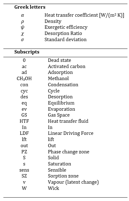
The adsorption heat pump module (AHPM), illustrated in Figure 1a, consists of a sorption zone (SZ, red) and a phase-change zone (PZ, blue), connected via a shared refrigerant gas space (GS).
The PZ comprises a double-walled cylindrical housing with water flowing through the annular gap to either remove or supply heat during condensation and evaporation, respectively. Phase change occurs on an internal capillary (wick) structure that both increases the heat transfer surface and stores liquid refrigerant. Capillary forces ensure uniform refrigerant distribution, enabling gravity-independent operation and contributing to compact system integration. In this study, methanol is chosen as the refrigerant because of its higher evaporation pressure and suitability for operation below 0 °C.
The SZ contains moulded activated carbon adsorbent bodies, which have been developed and characterized in previous studies [5]. For thermal coupling to the HTF, various heat exchanger configurations are possible. Maier and Stripf [18] analysed a flat-tube geometry with stacked adsorbent bodies. In this work, an alternative design is studied in which the moulded bodies are directly glued onto flat heat exchanger tubes, following the approach in [4].
The SZ contains moulded activated carbon adsorbent bodies, which have been developed and characterized in previous studies [5]. For thermal coupling to the HTF, various heat exchanger configurations are possible. Maier and Stripf [18] analysed a flat-tube geometry with stacked adsorbent bodies. In this work, an alternative design is studied in which the moulded bodies are directly glued onto flat heat exchanger tubes, following the approach in [4].
The SZ is supplied with heat transfer fluid (HTF) at a temperature of Tdes≈ 388 K during desorption and a temperature of Tad≈ 303-323 K during adsorption. Simultaneously, the PZ is maintained at Tcon= Tad ≈ 303-323 K during condensation, and T_ev≈ 288 K during evaporation. Unlike conventional systems, no vacuum valves are required, as all switching is achieved via fluid control valves that adjust HTF flow and temperature. The internal pressure follows the saturated vapor pressure corresponding to the PZ temperature.
The thermodynamic cycle is illustrated in the Clapeyron diagram (Figure 1b) for the representative values Tdes= 388 K, Tad= Tcon = 313 K, and T_ev = 288 K. In this log(p) vs. -1/T representation, the equilibrium loading lines appear as straight lines. The temperature in Kelvin is given on the secondary axis. The equilibrium is modelled using the Dubinin-Astakhov equation [19]:
where W0 is the maximum specific pore volume, E the characteristic energy, Runi the universal gas constant, M the molar mass, ps the saturation pressure at Tad, ρ the density of adsorbed methanol (approximated using saturated liquid data), and Xeq the equilibrium loading [kg refrigerant/kg adsorbent]. Parameters W0, E and n are based on experimental data from [5].
The dashed and dash-dotted lines in Figure 1b indicate relevant pressure and temperature levels. The cycle starts at states 1/1’, where both SZ and PZ are isosterically heated by the HTF, supplying sensible heat Qsens and initiating desorption heat Qdes|X reaching states 2/2’. Desorption then continues isobarically with Qsens|p supplied to the adsorber while methanol desorbs and condenses in the PZ, releasing Qcon. Once equilibrium is reached (state 3), both zones are cooled simultaneously, and the internal pressure drops. The system releases heat (Qsens and Qad||X) to the corresponding HTF until reaching states 4/4’. During the subsequent isobaric adsorption, Qad|pis removed from the adsorber, and methanol evaporates in the PZ using environmental heat Qev. The heat released during adsorption and condensation can be used for space-heating system, improving the overall system efficiency.
3.2. Figures of Merit
To evaluate the efficiency of the module, the coefficient of performance (COP) is calculated based on the integrated heat flows over a full operating cycle, rather than instantaneous power values. This approach is necessary because the heat pump operates in alternating, transient modes [20]. The heating COPh is defined by:
where the terms represent the integrated heat quantities associated with adsorption (Qad|X, Qad|p), condensation (Qcon), sensible heat losses (Qsens), and desorption (Qdes|X), Qdes|p)).
These energy quantities are derived from energy balances over the SZ and the PZ, using the HTF mass flow rates ![]() and
and ![]() , the specific heat capacity cp, and the inlet and outlet temperatures, respectively. For the SZ during the adsorption half-cycle, the heat is calculated as:
, the specific heat capacity cp, and the inlet and outlet temperatures, respectively. For the SZ during the adsorption half-cycle, the heat is calculated as:

and for the PZ during the desorption/condensation half-cycle:

The desorption heat is computed using Eq. 3, but with integration limits corresponding to those in Eq. 4 (i.e. the first half-cycle). Here, tcyc denotes the total duration of one full operating cycle and χ= tdes/tcyc the desorption ratio. These equations account for changes in HTF properties, especially specific heat capacity, due to significant temperature variations between inlet and outlet, which are particularly pronounced during the transitions between adsorption/evaporation and desorption/condensation phases.
The average thermal output ![]() per cycle is calculated by summing the adsorption and condensation heat contributions and dividing by the cycle time:
per cycle is calculated by summing the adsorption and condensation heat contributions and dividing by the cycle time:

Additionally, an exergetic evaluation has been performed. Since the exergy analysis represents an application of the second law of thermodynamics, it provides further information on efficiency relative to a reversible process. To calculate the exergy of adsorption the following equation is used:

Here, Ex,ad is the exergy associated with the heat released during adsorption. The dead-state temperature T0 is kept constant, and the adsorption heat Qad is calculated using Eq. 3.
In a similar way, the exergy for condensation are calculated.


To obtain a dimensionless efficiency metric, the usable exergy is related to the supplied exergy

The definition of this exergy efficiency follows that given by Dincer and Rosen [21].
4. Modelling
4.1. Assumptions and System Description
The modelling of the adsorption heat pump module (AHPM) is based on the conservation equations for mass and energy. To reduce complexity and computational effort, several simplifying assumptions are made, as listed in Table 1.
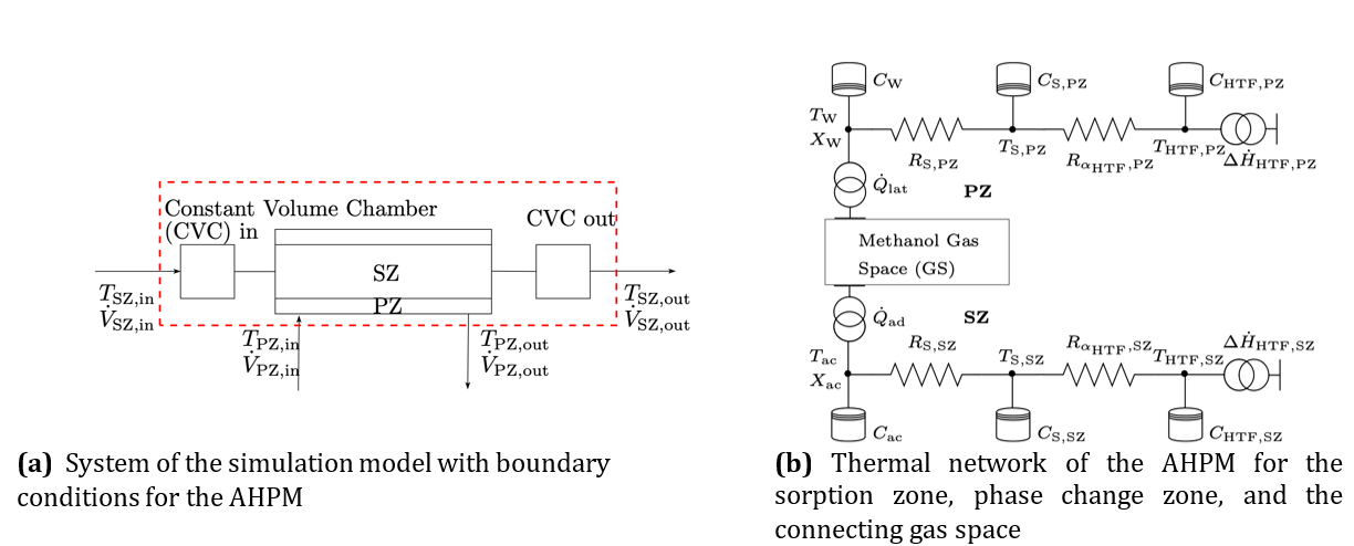
A schematic representation of the simulated system and its thermal network is shown in Figure 2. The red dashed rectangle in Figure 2a defines the system boundary for the simulation. The inlet and outlet volumes of the SZ are modelled using the Constant Volume Chamber (CVC) block from the Simscape Thermal Liquid library. The core of the simulation model, which includes the SZ and PZ, is implemented in the object-oriented Simscape language and is described in more detail in Section 4.2.
Table 1. Model assumptions used for the simulation
|
Thermal Assumptions |
Geometric and Fluid Assumptions |
|
1. The module is adiabatic to the environment. 2. Uniform temperature in the PZ (capillary, inner cylinder, fluid). 3. Uniform temperature in the SZ (carbon, solid, fluid). 4. Heat transfer between SZ and PZ occurs solely via methanol vapor transport. |
5. The unadsorbed vapor behaves as an ideal gas. 6. Axial temperature gradients along the module are neglected. 7. Inlet/outlet volumes of the PZ are considered negligible. 8. Mass transfer resistance within the activated carbon is neglected. |
The boundary conditions for the simulation are the volume flow rates ![]() and
and ![]() , and the
corresponding inlet temperatures
, and the
corresponding inlet temperatures ![]() and
and ![]() . These are implemented as ideal sources from the Thermal Liquid library. Outlet values are computed by the model.
. These are implemented as ideal sources from the Thermal Liquid library. Outlet values are computed by the model.
4.2. Mathematical Modelling
The model divides the system into thermal networks representing the SZ and PZ, coupled through a shared methanol gas space (GS). The corresponding thermal network structure is depicted in Figure 2b. Temperatures are calculated at each node (solid node: index S; heat transfer fluid: index HTF; activated carbon: index ac; wick structure: index W). Each node’s temperature evolution is governed by heat capacities C, conduction resistances RS, convection resistances Rα, and heat sources including adsorption heat ![]() , latent heat
, latent heat ![]() , and enthalpy flow difference
, and enthalpy flow difference ![]() due to HTF transport within the PZ
and SZ. The heat sources due to adsorption and the latent heat are modeled
using specific enthalpies for adsorption
due to HTF transport within the PZ
and SZ. The heat sources due to adsorption and the latent heat are modeled
using specific enthalpies for adsorption ![]() and phase change
and phase change ![]() as follows:
as follows:
Eq. 6 distinguishes between evaporation (first case) and condensation (second case). In the condensation case, the second term accounts for the sensible heat associated with the superheated methanol vapor, where is the specific heat capacity of methanol vapor.
The mass flows of methanol to and from the PZ and SZ, denoted as ![]() and
and ![]() respectively, are determined by the mass
of the wick structure
respectively, are determined by the mass
of the wick structure ![]() , the mass of the activated carbon
, the mass of the activated carbon ![]() , and their respective loading change
rates
, and their respective loading change
rates ![]() :
:
For activated carbon, the rate of adsorption or desorption is modelled using the linear driving force (LDF) model [22]:
where KLDF is a kinetic time constant, Xeq is the equilibrium loading from Eq. 1, and Xac is the instantaneous loading.
The rate of loading change in the wick structure is determined by equating Eq. 6 with Newton’s law of cooling, yielding:
Here, the lateral surface of the inner cylinder defines the reference surface Aref. Previous studies on finned tubes suggest that the evaporation heat transfer coefficient ![]() remains nearly constant until the
wick structure approaches dryness, assuming natural convection as the primary
mechanism [23].
In this study, it is therefore set constant at
remains nearly constant until the
wick structure approaches dryness, assuming natural convection as the primary
mechanism [23].
In this study, it is therefore set constant at ![]() = 950 W/(m2K). This value
is lower than reported by [14] due to the differences in geometry and the lower
latent heat of methanol compared to water.
= 950 W/(m2K). This value
is lower than reported by [14] due to the differences in geometry and the lower
latent heat of methanol compared to water.
A phenomenological approach is adopted for the condensation heat transfer coefficient ![]() accounting for the influence of wick loading:
accounting for the influence of wick loading:

These models for the heat transfer coefficients during evaporation and condensation are approximated; detailed fundamental studies are required to precisely describe heat transfer mechanisms within the wick structure.
Temperature evolution at each node and in the gas space is governed by the transient energy balance
where C represents the thermal capacity at the node. While Eq. 13 assumes time-invariant material data for simplicity, loading-dependent heat capacities of the wick and activated carbon are updated after each time step. Additionally, mass conservation in the gas space and the ideal gas law are simultaneously solved.
For numerical initialization, adsorption and evaporation equilibrium is assumed, with an initial 1 % deviation of the activated carbon loading below equilibrium. This minor deviation stabilizes calculation across different boundary conditions. The total methanol mass in the AHPM is set to 2.4 kg.

4.3. Experimental Validation of the Modell
To validate the simulation model, an experimental setup was developed to measure inlet and outlet conditions as well as the gas-phase pressure within the module. Volume flow rates in the test bench are measured using two Siemens Sitrans F M MAG sensors for the desorption and evaporation fluid circuits. These sensors have an uncertainty of 0,4 % ± 1 mm/s of the measured volume flow rate. A Kobold MIK sensor in the adsorption circuit is used to measure the volumetric flow rate with a precision of ± 0.32 l/min. The sensors are positioned to match the flow conditions of the respective zones (SZ and PZ). Temperatures are recorded with 3-wire PT100 class A sensors, corresponding to a maximum measurement error of ± 0.37 K. All experimental data are digitized using a National Instruments cDAQ-9178 acquisition system at a sampling interval of 0.05 s, enabling accurate capture of steep transient temperature gradients. Target temperatures for the validation tests are set to Tdes= 378 K, Tad= 308 K, and Tev= 288 K.
Figure 3 compares simulation results with measurements of the gas-space pressure and inlet/outlet temperatures. All data sets initially exhibit decaying transient behaviour that stabilizes after approximately five cycles. This behaviour is clearly visualized in the pressure plot. Starting from cycle six, a stable periodic behaviour is observed, which is analysed in detail in the temperature plots. The simulated PZ outlet temperature is slightly underestimated during condensation and in the later stages of evaporation. Similarly, the simulated SZ outlet temperature is slightly underestimated, except at the beginning of desorption, and marginally overestimated during adsorption. These discrepancies could be attributed to factors such as fluid inhomogeneities and sensor lag. The evaporation process is nearly isobaric, whereas the non-isobaric condensation process suggests a heat transfer bottleneck in the PZ.
The dominant source of deviation between simulation and experiment primarily arises from uncertainties in modelling the phase-change heat transfer coefficient within the wick structure during both evaporation and condensation. This limitation stems from the lack of suitable correlations available in the literature. Further studies are required to gain deeper insight into the underlying physics and to develop a more accurate modelling approach for the design presented here.
As shown in various simulation studies ([18],[24]), the assumption of homogeneous temperature, pressure, and loading distributions along the fluid flow direction strongly depends on geometry and is often not valid. Resolving these gradients here would substantially increase computational cost. Since the objective of this study is to provide an energy and exergy analysis across a broad range of parametric variations, the model prioritizes computational efficiency over absolute accuracy.
The accuracy of the simulation model is quantitatively assessed by calculating the standard deviation between simulation and measurement, following the approach of [25].

 and at a fixed volumetric flow rate of 30 l/min. Left: variation with evaporation temperatures. Right: variation with cycle time.
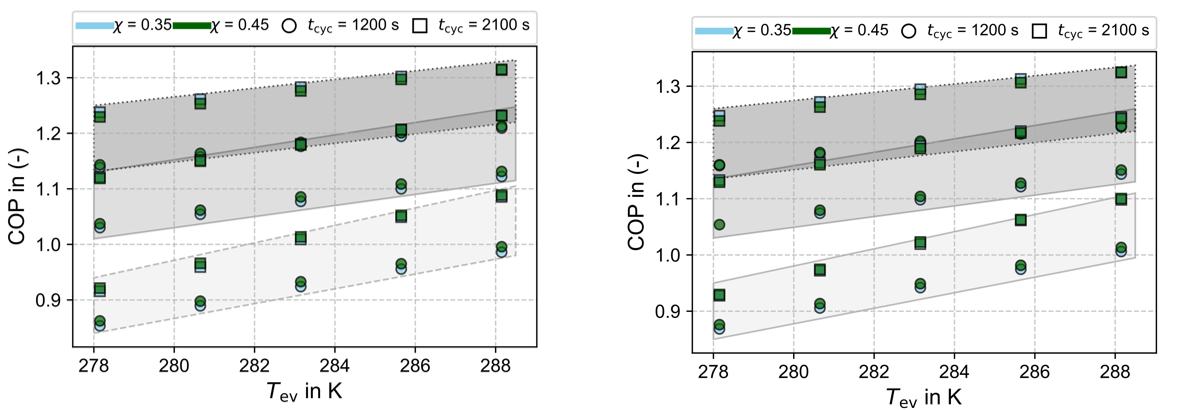
 = l/min; right: = 30 l/min). The shaded parallelograms represent constant adsorption temperatures: light gray for 303.15 K, medium gray for 313.15 K, and dark gray for 323.15 K.
In this equation and correspond to the simulated and measured values, while and account for the difference of the maximum and minimum measured value and the time interval considered in the equation, respectively.
The resulting values are for one cycle ![]()
![]() , and
, and ![]() indicating sufficient agreement and
highlighting opportunities for further parameter refinement.
indicating sufficient agreement and
highlighting opportunities for further parameter refinement.
5. Results of the Parameter Analysis
A parameter study is conducted with operating conditions chosen to reflect typical scenarios for building heating applications. The desorption temperature is fixed at Tdes= 388 K, while the adsorption temperature ranges from 303 to 323 K and the evaporation temperature from 278 to 288 K. HTF volume flow rates vary between 15 and 30 l/min, the desorption ratio χ between 0.35–0.5, and cycle times tcyc from 1200 to 2100 s.
Figure 4 illustrates the variation of COP and average heat output ![]() with adsorption temperature for different evaporation temperatures and cycle times. Both COP and
with adsorption temperature for different evaporation temperatures and cycle times. Both COP and ![]() improve as adsorption temperature decreases and evaporation temperature increases. However, increasing the cycle time results in a reduced average heat output
improve as adsorption temperature decreases and evaporation temperature increases. However, increasing the cycle time results in a reduced average heat output ![]() but an improved COP (Figure 4, right). Therefore, the optimal cycle time is a trade-off between maximizing COP and satisfying the required average heat output of the target application. Figure 5 further explores COP dependency on evaporation temperature at different volume flow rates.
but an improved COP (Figure 4, right). Therefore, the optimal cycle time is a trade-off between maximizing COP and satisfying the required average heat output of the target application. Figure 5 further explores COP dependency on evaporation temperature at different volume flow rates.
Constant adsorption temperature is illustrated with parallelograms in light grey for 303.15 K and in grey and dark grey for 313.15 K and 323.15 K, respectively. Increasing volumetric flow leads to a slight rise in COP, though the rate of increase diminishes at longer cycle times. This trend suggests that both longer cycle durations and higher volume flows allow the system to more closely approach theoretical equilibrium conditions, thereby limiting further gains. The desorption ratio χ influences COP, although to a lesser extent than other parameters. However, systems with pronounced mass-transfer limitations might exhibit stronger sensitivity to χ. Due to the clear interactions observed between the desorption ratio and other parameters, further detailed investigations are recommended, particularly regarding its use in system control strategies.
Additionally, Figure 5 illustrates that COP can drop below unity at higher adsorption and lower evaporation temperatures, primarily due to substantial heat losses during cyclic temperature transitions. Such losses can be mitigated in multi-module systems employing heat recovery cycles. Moreover, the achievable temperature lift (ΔTlft=Tad-Tev) for a COP > 1 is more sensitive to variations in adsorption temperature than evaporation temperature. Therefore, reducing the adsorption temperature should be prioritized for improved efficiency, as it enables a larger refrigerant loading range between adsorption and desorption.
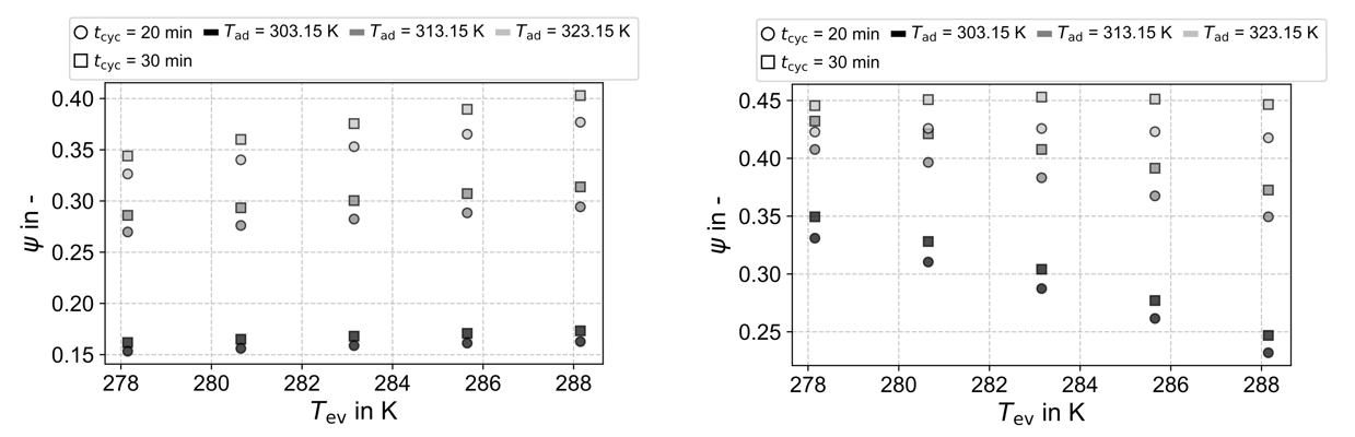
Figure 6 illustrates the exergy efficiency as a function of the evaporation temperature. In the left panel, where the dead-state conditions are kept constant, the data indicate that the exergy efficiency increases with rising evaporation temperature. Moreover, the exergy efficiency also increases with higher adsorption temperatures. This behaviour contrasts with the energy analysis based on the coefficient of performance (COP). Since exergy analysis reflects how closely a process approaches the thermodynamic limit, these results suggest that higher adsorption temperatures enable the process to operate closer to this limit, even though the overall energy efficiency is lower than for reduced adsorption temperatures. The analysis clearly indicates that performance improvements could be achieved by enhancing system behaviour at lower adsorption temperatures. One potential approach is to modify the activation process of the activated carbon to optimize it for operation under low-temperature adsorption conditions.
In contrast, the right panel of Figure 6 presents the exergy analysis under varying dead-state conditions, where the dead-state temperature is set equal to the evaporation temperature. This adjustment significantly affects the exergy results. Because differing dead-state definitions prevent meaningful comparison between simulations with different evaporation temperatures, this depiction serves to emphasize the necessity of maintaining consistent dead-state conditions both within a given study and across different studies for valid exergy comparisons.
6. Conclusion
This study introduces a novel adsorption heat pump module (AHPM) featuring an integrated capillary-structured heat exchanger that serves as both evaporator and condenser. A validated theoretical model was developed, demonstrating close agreement with experimental data. The calculated COP values underline the AHPM’s suitability for integration into hybrid heating systems in building applications. A comprehensive parameter analysis examined the effects of adsorption and evaporation temperatures, cycle time, heat-exchanger flow rate, and desorption ratio. The key findings are:
- The COP and average heat output are highly sensitive to variations in adsorption and evaporation temperatures, as well as to cycle time. Thus, careful optimization of these parameters is crucial for maximizing performance.
- Increasing evaporation temperatures and decreasing adsorption temperatures significantly improve both COP and heat output, emphasizing the benefit of temperature-level optimization.
- Longer cycle times increase COP but reduce total heat output, indicating a trade-off between efficiency and capacity.
- Higher heat exchanger volumetric flow rates slightly improve COP and heat output.
- The desorption ratio exhibits a minor influence on COP but may play a valuable role in refining control strategies, particularly in systems experiencing significant mass transfer limitations.
- The adsorption temperature influences COP and exergy efficiency more strongly than evaporation temperature, making it the critical factor for system performance optimization and further design improvements.
By introducing and thoroughly evaluating this novel module design, the study contributes to improving the practical feasibility and economic viability of adsorption heat pump systems. The design shows strong potential for industrial waste-heat recovery, for retrofitting existing building-heating infrastructure, and for improving the efficiency of biomass-based energy systems.
The results indicate that subsequent work with this or similar designs should concentrate on integrating the module into a complete system and examining advanced cycles such as mass- and heat-recovery schemes. This is particularly relevant because both SZ and PZ require recovery strategies. The exergy analysis further suggests that material design can be tailored to specific temperature levels. Experimental studies are required to verify these findings.
Acknowledgements
Financial support from the Ministry of Economic Affairs, Labor and Tourism of the state government of Baden-Württemberg (Germany) within the investBW program (Grant No. BW1_2083/02) and the Deutsche Bundesstiftung Umwelt (Grant No. 38442/01) are gratefully acknowledged.References
[1] Eurostat, 'Energy consumption in households - Statistics Explained', European Commission, 2025. Accessed: Nov. 06, 2025. [Online]. Available: https://ec.europa.eu/eurostat/statistics-explained/SEPDF/cache/58200.pdfView Article
[2] F. Meunier, 'Adsorption heat powered heat pumps', Appl. Therm. Eng., vol. 61, no. 2, pp. 830-836, Nov. 2013, doi: 10.1016/j.applthermaleng.2013.04.050.View Article
[3] H. Z. Hassan, A. A. Mohamad, Y. Alyousef, and H. A. Al-Ansary, 'A review on the equations of state for the working pairs used in adsorption cooling systems', Renew. Sustain. Energy Rev., vol. 45, pp. 600-609, May 2015, doi: 10.1016/j.rser.2015.02. 008.View Article
[4] O. Kraft, M. Stripf, and U. Hesse, 'Heat and mass transfer in activated carbon composites with artificial macro pores for heat pump applications', Adsorption, vol. 25, no. 6, pp. 1121-1133, Aug. 2019, doi: 10.1007/s10450-019-00077-7.View Article
[5] O. Kraft, Adsorber-Compounds für mobile und stationäre Adsorptionswärmepumpen mit hoher Leistungsdichte S.l.: Logos Verlag Berlin, 2021.
[6] D. Wang, J. Zhang, X. Tian, D. Liu, and K. Sumathy, 'Progress in silica gel-water adsorption refrigeration technology', Renew. Sustain. Energy Rev., vol. 30, pp. 85-104, Feb. 2014, doi: 10.1016/ j.rser.2013.09.023.View Article
[7] L. Calabrese, P. Bruzzaniti, D. Palamara, A. Freni, and E. Proverbio, 'New SAPO-34-SPEEK composite coatings for adsorption heat pumps: Adsorption performance and thermodynamic analysis', Energy, vol. 203, p. 117814, Jul. 2020, doi: 10.1016/ j.energy.2020.117814.View Article
[8] B. Mette, H. Kerskes, H. Drück, and H. Müller-Steinhagen, 'Experimental and numerical investigations on the water vapor adsorption isotherms and kinetics of binderless zeolite 13X', Int. J. Heat Mass Transf., vol. 71, pp. 555-561, Apr. 2014, doi: 10.1016/j.ijheatmasstransfer.2013.12. 061.View Article
[9] J. A. Shamim et al., 'Review of the potential and challenges of MOF-based adsorption heat pumps for sustainable cooling and heating in the buildings', Energy, vol. 323, p. 135846, May 2025, doi: 10.1016/j.energy.2025.135846.View Article
[10] A. N. Shmroukh, A. H. H. Ali, and S. Ookawara, 'Adsorption working pairs for adsorption cooling chillers: A review based on adsorption capacity and environmental impact', Renew. Sustain. Energy Rev., vol. 50, pp. 445-456, Oct. 2015, doi: 10.1016/j.rser. 2015.05.035.View Article
[11] S. J. Metcalf, Z. Tamainot-Telto, and R. E. Critoph, 'Application of a compact sorption generator to solar refrigeration: Case study of Dakar (Senegal)', Appl. Therm. Eng., vol. 31, no. 14-15, pp. 2197-2204, Oct. 2011, doi: 10.1016/j.applthermaleng. 2010.11.001.View Article
[12] M. M. Saleh, R. Al-Dadah, S. Mahmoud, E. Elsayed, and O. El-Samni, 'Wire fin heat exchanger using aluminium fumarate for adsorption heat pumps', Appl. Therm. Eng., vol. 164, p. 114426, Jan. 2020, doi: 10.1016/j.applthermaleng.2019.114426.View Article
[13] Q. W. Pan, R. Z. Wang, and L. W. Wang, 'Comparison of different kinds of heat recoveries applied in adsorption refrigeration system', Int. J. Refrig., vol. 55, pp. 37-48, Jul. 2015, doi: 10.1016/j.ijrefrig. 2015.03.022.View Article
[14] R. Z. Wang, 'Performance improvement of adsorption cooling by heat and mass recovery operation', Int. J. Refrig., vol. 24, no. 7, pp. 602-611, Jul. 2001, doi: 10.1016/s0140-7007(01)00004-4.View Article
[15] R. E. Critoph, 'Simulation of a continuous multiple-bed regenerative adsorption cycle', Int. J. Refrig., vol. 24, no. 5, pp. 428-437, Aug. 2001, doi: 10.1016/ S0140-7007(00)00026-8.View Article
[16] U. Wittstadt et al., 'A novel adsorption module with fiber heat exchangers: Performance analysis based on driving temperature differences', Renew. Energy, vol. 110, pp. 154-161, Sep. 2017, doi: 10.1016/j.renene.2016.08.061.View Article
[17] R. Burk and L. Ludwig, 'Sorptionswärmeüber-tragungsmodul', DE 10 2018 212 820 A1, Mar. 07, 2019 Accessed: Jul. 29, 2025. [Online]. Available: View Article
[18] T. Maier and M. Stripf, 'Distributed parameter model of a novel heat pump adsorber design using 3D-FEM', Appl. Therm. Eng., vol. 278, p. 126963, Nov. 2025, doi: 10.1016/j.applthermaleng.2025. 126963.View Article
[19] M. M. Dubinin and V. A. Astakhov, 'Development of the concepts of volume filling of micropores in the adsorption of gases and vapors by microporous adsorbents: Communication 1. Carbon adsorbents', Bull. Acad. Sci. USSR Div. Chem. Sci., vol. 20, no. 1, pp. 3-7, Jan. 1971, doi: 10.1007/BF00849307.View Article
[20] D. B. Boman, A. W. Raymond, and S. Garimella, Adsorption Heat Pumps: Fundamentals and Applications. in Mechanical Engineering Series. Cham: Springer International Publishing, 2021. doi: 10.1007/978-3-030-72180-0.View Article
[21] I. Dincer and M. A. Rosen, Exergy, Energy, Environment and Sustainable Development, 3. Elsevier, 2021.View Article
[22] M. H. Chahbani, J. Labidi, and J. Paris, 'E€ect of mass transfer kinetics on the performance of adsorptive heat pump systems', Appl. Therm. Eng., 2002.View Article
[23] G. B. Abadi and M. Bahrami, 'Combined evaporator and condenser for sorption cooling systems: A steady-state performance analysis', Energy, vol. 209, p. 118504, Oct. 2020, doi: 10.1016/j.energy. 2020.118504.View Article
[24] A. W. Raymond and S. Garimella, 'Distributed parameter simulation of annular-finned tube sorption bed', Int. J. Heat Mass Transf., vol. 166, p. 120755, Feb. 2021, doi: 10.1016/ j.ijheatmasstransfer.2020.120755.View Article
[25] M. Schicktanz and T. Núñez, 'Modelling of an adsorption chiller for dynamic system simulation', Int. J. Refrig., vol. 32, no. 4, pp. 588-595, Jun. 2009, doi: 10.1016/j.ijrefrig.2009.02.011.View Article