Journal of Fluid Flow, Heat and Mass Transfer (JFFHMT)
ISSN: 2368-6111

Volume 12 - Year 2025 - Pages 397-403
DOI: 10.11159/jffhmt.2025.039
Curved Riblet Tips for Drag Reduction in Water Pipes
Mirvahid Mohammadpour Chehrghani1,2, Doekle Yntema2, David Matthews1, Matthijn de Rooij1, Jamal Seyyed Monfared Zanjani1
1Faculty of Engineering Technology, University of Twente, 7500AE, Enschede, the Netherlands
m.mohammadpourchehrghani@utwente.nl; d.t.a.matthews@utwente.nl; m.b.derooij@utwente.nl;
j.seyyedmonfaredzanjani@utwente.nl;
2Wetsus, European Centre of Excellence for Sustainable Water Technology, Oostergoweg 9, 8911 MA Leeuwarden, The Netherlands
mche@wetsus.nl; doekle.yntema@wetsus.nl
Abstract - This study examines the role of riblet tip curvature in controlling drag in pipe flow and identifies how subtle geometric variations can alter performance. Three tip shapes were investigated: conventional flat tips, concave tips and convex tips. The riblets were manufactured using masked stereolithography 3D printing and systematically tested across a broad range of Reynolds numbers. The results show that tip curvature shows little influence under laminar conditions (Re < 2200), but becomes decisive once the flow enters transitional and turbulent regimes (Re > 2200). Convex tips consistently produced weaker drag reduction than flat tips, indicating that outward curvature may disrupt near-wall vortex organization. In contrast, concave tips enhanced drag reduction, yielding up to 30 percent drag reduction at Re ≈ 6000. However, the benefit diminished at both lower and higher Re, indicating strong sensitivity to flow–scale interactions. These findings demonstrate that riblet effectiveness is dependent on tip curvature and flow regime, and they provide new design principles for engineering advanced riblet surfaces that can reduce frictional losses and energy consumption in pipelines.
Keywords: Drag reduction; Riblets; Turbulent flow; Pipe flow; Shark-skin; Curved Riblet.
© Copyright 2025 Authors - This is an Open Access article published under the Creative Commons Attribution License terms Creative Commons Attribution License terms. Unrestricted use, distribution, and reproduction in any medium are permitted, provided the original work is properly cited.
Date Received: 2025-01-23
Date Revised: 2025-09-25
Date Accepted: 2025-10-08
Date Published: 2025-12-01
1. Introduction
Pipelines are essential to numerous industries, such as water distribution systems, where efficient flow is critical to reducing energy consumption [1]. Turbulent flow in pipelines induces significant energy losses [2], primarily due to near-wall streamwise vortices that increase frictional drag, reducing hydraulic performance and increasing operational costs. To mitigate these losses, efforts have focused on manipulating near-wall turbulence, with biomimetic surfaces emerging as a promising strategy [3], [4].
Among these approaches, biomimetic riblet surfaces inspired by the unique skin structure of fast-swimming sharks, have shown remarkable potential for drag reduction [5], [6]. Experimental and numerical studies have reported up to 10% drag reduction under optimal conditions for riblets with blade geometries [7], [8]. These surfaces disrupt turbulent eddies near the boundary layer, altering flow dynamics to minimize energy dissipation [9], [10]. However, most studies have focused on continuous riblets with flat-tips, leaving the influence of tip curvature largely unexplored.
Biomimetic riblet research investigates geometries beyond continuous blade riblets. Multiscale and hierarchical layouts seek coupling with a range of near wall structures [11], [12], [13]. Staggered and cuboidal surface patterns can constrain vortex rotation and expansion [14]. Studies show that crest definition influences the organization of near wall turbulent structures [15]. In addition, sinusoidal riblet shapes and segmented arrays intermittently interrupt vortex translation [16], [17]. Studies on superhydrophobic grooved surfaces indicate that groove curvature and topology influence drag by altering slip, pressure distribution, and near wall shear [18], [19]. Together, these developments motivate closer examination of tip shape and curvature as controlling parameters for riblet performance in pipe flow.
Recent experiments on shark skin inspired riblets in pipe flow show that drag reduction performance depends on both pipe diameter and riblet geometry, with larger diameters shifting the optimum toward higher values [20], [21]. These findings highlight the need to account for pipe curvature in riblet design and indicate that configurations optimized for channel flows require separate optimization for pipe flows. Chehrghani et al. demonstrated up to 6% drag reduction in pipes under optimal flow conditions [20]. However, deviations from the optimal spacing led to performance deterioration and, in some cases, an increase in drag. To identify the optimal spacing, they developed a practical correlation that predicts the spacing for maximum drag reduction as a function of riblet geometry and pipe diameter, achieving agreement with experimental data within 5% across all tested cases.
While the drag reducing benefits of biomimetic riblets are well known, the impact of the tip of the riblet curvature has received limited attention. Flat-tip riblets, though effective, may not fully optimize drag reduction or flow dynamics. Additionally, fabrication processes can introduce unavoidable tip irregularities or radii to the riblet tips. This highlights the need to investigate riblet tip curvature to better understand its effects under practical pipeline flow conditions.
This study addresses these gaps by experimentally investigating the impact of longitudinal riblets with varying tip curvatures on drag reduction in both laminar and turbulent pipe flows. The findings provide valuable insights into the role of riblet tip curvature in influencing drag, paving the way for the development of advanced surface designs to improve pipeline efficiency.
2. Materials and Methods
2.1. Experimental Methodology
A water flow loop system was designed to apply a steady flow and measure pressure drop, enabling evaluation of drag reduction in pipes under fully developed flow conditions as shown in Figure 1. Tap water from a ground-level reservoir was pumped into a constant-head tank, maintaining a head of 2.6 m. This gravity-driven flow system minimized pulsations from the pump, ensuring a stable flow for accurate measurements.
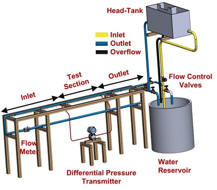
The setup included an inlet section, a test section, and a differential pressure transmitter to measure the pressure drop over the test section. Flow rate was controlled using a globe valve, enabling measurements across a range of Reynolds numbers. The inlet section, with an L/D ratio of approximately 75, ensured hydrodynamically fully developed flow necessary for the flow to become steady for pressure drop measurement.
The Reynolds number range was selected to span laminar, transitional, and moderate turbulent pipe flow relevant to drinking water distribution. The selection also ensured fully developed conditions in the test section and stable operation of the constant head loop at the available flow rates. Pressure drop measurements were conducted over an approximately 0.82 m interval using symmetrically arranged pressure taps to validate accuracy of the measurement. The water then exited the test section, flowed through an outlet section, and returned to the reservoir, completing the open flow loop system.
2.2. Sample Design and Fabrication
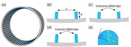
To evaluate the effect of riblet tip curvature on drag change in pipes, three distinct riblet designs were tested, as illustrated in Figure 2. The riblets were aligned with the flow direction inside the pipes, as shown in Figure 2a. Riblets with a traditional flat tip are depicted in Figure 2b, while those with negative tip curvature were designated as concave riblets (Figure 2c), and those with positive tip curvature were referred to as convex riblets (Figure 2d). A detailed illustration of the riblet tip curvature and the key design parameters is provided in Figure 2e.
Samples were designed using SolidWorks, with each pipe having a length of approximately 135 mm, constrained by the maximum printable height of the 3D printer, as detailed below. To meet the required length for fully developed flow conditions (L/D > 10), multiple shorter pipes were fabricated and joined using tri-clamps. The pipes had an effective diameter of 28 mm and surface roughness of 2 µm, with the textured pipes’ diameter defined as the equivalent diameter of a smooth, untextured pipe with the same cross-sectional area.
Fabrication was performed using a masked stereolithography (MSLA) 3D printing process using the Prusa SL1S 3D resin printer and the CW1S Curing and Washing Machine for post processing. The material used for printing was Prusament Resin Tough Rich Black.
2.3. Processing of Experimental Data
The Darcy friction factor was calculated using pressure drop measurements, as follows [22] :
Here, ∆p is the measured pressure drop across the pipe length ∆L, ρ , ρ signifies the density of water and Q denotes the fluid volume flow rate.
To quantify drag reduction in pipes with riblets fexp compared to the reference untextured pipe fr, the percentage drag change was defined as:

Negative values of Drag change % indicate drag reduction, while positive values correspond to increased drag.
The experimentally determined friction factors for bare 3D printed pipe compared with theoretical predictions using the Colebrook equation [23]:

In this equation, fpred is the predicted Darcy friction factor from Colebrook, e is the surface roughness of the pipe, D is the pipe diameter, and Re is the Reynolds number.
The Reynolds number was calculated as [24]:

where ![]() is the bulk fluid velocity derived from the measured flow rate Q, and ϑ is the kinematic viscosity of the fluid
is the bulk fluid velocity derived from the measured flow rate Q, and ϑ is the kinematic viscosity of the fluid
3. Results and Discussion
3.1. Sample Characterization
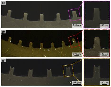
Optical microscopy images in Figure 3 provide a detailed view of the MSLA 3D-printed structures. Figure 3a illustrates riblets with traditional flat tips, accompanied by magnified images that provide more detailed view of the riblet tip. Figure 3b displays convex riblets, while Figure 3c presents concave riblets. These images demonstrate the high precision of the 3D printing process, confirming that the riblet tip curvatures were accurately fabricated to ensure reliable data collection during the experimental study.
3.2. Experimental Validation
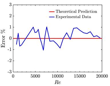
The friction factor (f) for the 3D-printed untextured pipe was compared with values derived from the Colebrook correlation to validate the experimental setup and measurement system [23]. The percentage error (Error%) was analyzed and found to be approximately ±1% as shown in Figure 4. confirming the accuracy of the measurements and the reliability of the experimental data.
3.3. Drag Change measurement
The performance of riblets with varying tip curvatures was systematically evaluated by measuring the percentage drag change (DC%) across a range of Reynolds numbers (Re), as shown in Figure 5. The results reveal a relationship between riblet tip curvature and drag reduction, particularly as the flow transitions from laminar to turbulent regimes.
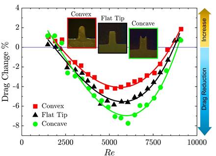
In the laminar flow region (Re ≤ 2200), the influence of riblet tip curvature on drag is minimal, with variations remaining below 0.5% compared to traditional flat-tip riblets [25]. This negligible effect is expected, as laminar flows are dominated by viscous forces, and the near-wall region remains relatively uniform, rendering subtle geometric differences in tip shape ineffective for drag reduction [26].
In transitional and turbulent regimes (Re > 2200), tip curvature shows a more pronounced and complex effect [25]. Convex-tipped riblets consistently exhibit lower drag reduction than flat-tip designs, likely due to their protruding geometry, which increases the wetted area exposed to high-velocity regions. This exposure amplifies interactions with streamwise vortices, intensifying near-wall turbulence and contributing to higher drag [27]. These vortices rotate around their axis in the direction of the mean flow, intensifying near-wall turbulence and contributing to increased drag.
Conversely, concave-tipped riblets demonstrate superior drag reduction performance, attributed to their sharper edges and reduced contact area, which limit vortex interaction and spanwise flow effects [8].
This design achieved its peak performance at moderate Reynolds numbers (5500 ≤ Re ≤ 6500), providing approximately 30% improvement over flat-tip riblets at Re ≈ 6000. The enhanced performance at these conditions is likely due to optimal alignment between the riblet geometry and turbulent flow structures, effectively suppressing near-wall turbulence [28]. However, this improvement is not monotonic and varies significantly with Reynolds number. At moderate Reynolds numbers (5500 ≤ Re ≤ 6500), concave riblets achieve their peak performance, with drag reduction enhancements of approximately 30% compared to flat-tip riblets at Re ≈ 6000. This improvement results from an optimal alignment of the riblet geometry with the flow structures at these Reynolds numbers, where the interaction between the riblets and turbulent eddies is most effective in suppressing near-wall turbulence [28]. At lower Reynolds numbers (e.g., Re ≈ 4000), the enhancement provided by concave riblets diminishes to less than 5%. This reduced performance is likely a result of weaker turbulence in this regime, which limits the riblets' capacity to interact with and influence flow structures effectively. Conversely, at higher Reynolds numbers (e.g., Re ≈ 9000), the thickness of the viscous sublayer decreases, a factor that plays a crucial role in suppressing turbulent activities [29]. The reduction in viscous sublayer thickness leads to intensified turbulent fluctuations near the solid wall, thereby increasing turbulence levels. This stronger near-wall turbulence is hypothesized to reduce the effectiveness of concave riblets in mitigating drag, as their ability to suppress these fluctuations may become less pronounced under such conditions.
As discussed in our previous study [20], riblet performance is influenced by the pipe diameter D and the height to spacing ratio h/s. The optimal riblet spacing for maximum drag reduction, increases as D increases. Additionally, for a fixed D, larger h/s shifts the optimal point toward lower values, consistent with stronger interaction within the viscous sublayer. Therefore, a separate design process is required when applying riblets to pipes of different diameters and when considering how tip curvature effects may scale to larger diameters.
The results demonstrate that riblet tip curvature plays a critical role in drag reduction performance in pipe flow. Convex-tipped riblets, which curve into the flow, increase the surface area exposed to high-shear near-wall turbulence and consequently exhibit diminished drag-reducing effectiveness compared to flat-tipped configurations. In contrast, concave-tipped riblets curve away from the flow, limiting surface exposure to high shear and promoting closer confinement of streamwise vortices near the riblet tip [30]. This confinement contributes to the enhanced drag reduction observed for concave surfaces relative to flat riblets. High-fidelity simulations have further shown that sharp, sharp-tipped V-shaped riblets improve drag reduction by lifting and redirecting near-wall vortices, while rounded-tip geometries result in reduced performance [15]. Additionally, a measurable shift in the mean velocity profile has been observed for sharp-tipped riblets compared to those with rounded tips. Collectively, these findings underscore the importance of tip geometry in riblet design and support the optimization of surface features for improved flow efficiency across a range of Reynolds numbers in pipeline systems.
4. Conclusion
This study demonstrates that traditional flat-tipped riblets can effectively reduce drag in pipe flows in transitional and turbulent regions. However, the degree of drag reduction depends on Reynolds numbers specific to the pipe diameter, the number of riblets, and their size. Beyond flat-tipped riblets, the influence of riblet tip curvature on drag reduction was investigated, focusing on concave-tipped and convex-tipped riblets. A gravity-driven fluid flow system was established to minimize pulsations and ensure stable flow, enabling accurate pressure drop measurements.
The results indicate that riblet tip curvature plays a significant role in drag reduction performance. Convex-tipped riblets with positive curvature exhibited less favorable drag reduction compared to flat-tipped riblets across all tested Reynolds numbers. In contrast, concave-tipped riblets demonstrated enhanced drag reduction potential compared to flat-tipped riblets. This suggests that riblet tip curvature influences drag performance, with concave designs showing potential for maximizing drag reduction under certain conditions.
Further analysis revealed that the drag reduction performance of concave-tipped riblets is non-monotonic. At moderate Reynolds numbers (e.g., Re ≈ 6000), concave riblets achieved up to 30% drag reduction compared to flat-tipped. However, their effectiveness diminished at both lower and higher Reynolds numbers, highlighting the interplay between flow conditions and riblet geometry.
Overall, this study provides valuable insights into the role of riblet tip curvature in improving pipeline efficiency. From an application perspective, the measured reductions in friction factor reduce the required pumping head and thereby lower energy use in water pipelines. Although masked stereolithography was used for prototyping in this study, the same geometries are compatible with scalable manufacturing, including extrusion of textured liners for installation in existing pipes. Long term performance will depend on material selection and service conditions. Therefore, we recommend further studies on durability, including abrasion, mineral scaling, and biofouling. These findings offer guidance for developing advanced surface designs optimized for specific flow conditions and support the potential of riblet technologies to enhance fluid transport in practical applications.
Acknowledgements
This work was performed in the cooperation framework of Wetsus, European Centre of Excellence for Sustainable Water Technology (www.wetsus.nl). Wetsus is co-funded by the European Union (Horizon Europe, LIFE, Interreg and EDRF), the Province of Fryslân and the Dutch Government: Ministry of Economic Affairs (TTT, SBO & PPS-I/TKI Water Technology), Ministry of Education, Culture and Science (TTT & SBO) and Ministry of Infrastructure and Water Management (National Growth Fund - UPPWATER). This work is part of a project that has received funding from the European Union’s Horizon 2020 research and innovation program under the Marie Sklodowska-Curie grant agreement No 665874. The authors like to thank the participants of the research theme “Smart water grids” for the fruitful discussions and their financial support
References
[1] L. W. Mays, Water distribution systems handbook. McGraw-Hill, 2000.
[2] S. B. Pope, Turbulent Flows. Cambridge University Press, 2000. doi: 10.1017/CBO9780511840531. View Article
[3] H. A. Abdulbari, H. D. Mahammed, and Z. B. Y. Hassan, "Bio-Inspired Passive Drag Reduction Techniques: A Review," ChemBioEng Reviews, vol. 2, no. 3, pp. 185-203, Jun. 2015, doi: 10.1002/CBEN.201400033. View Article
[4] B. Bhushan, Encyclopedia of Nanotechnology. Springer Netherlands, 2012. doi: 10.1007/978-90-481-9751-4. View Article
[5] S. Martin and B. Bhushan, "Fluid flow analysis of continuous and segmented riblet structures," RSC Adv, vol. 6, no. 13, pp. 10962-10978, Jan. 2016, doi: 10.1039/C5RA20944G. View Article
[6] Y. Zhu, F. Yang, and Z. Guo, "Bioinspired surfaces with special micro-structures and wettability for drag reduction: which surface design will be a better choice?," Nanoscale, vol. 13, no. 6, pp. 3463-3482, Feb. 2021, doi: 10.1039/D0NR07664C. View Article
[7] D. W. Bechert, M. Bruse, W. Hage, J. G. T. Van Der Hoeven, and G. Hoppe, "Experiments on drag-reducing surfaces and their optimization with an adjustable geometry," J Fluid Mech, vol. 338, pp. 59-87, May 1997, doi: 10.1017/S0022112096004673. View Article
[8] S. J. Lee and S. H. Lee, "Flow field analysis of a turbulent boundary layer over a riblet surface," Exp Fluids, vol. 30, no. 2, pp. 153-166, Feb. 2001, doi: 10.1007/s003480000150. View Article
[9] D. Goldstein, R. Handler, and L. Sirovich, "Direct numerical simulation of turbulent flow over a modeled riblet covered surface," J Fluid Mech, vol. 302, pp. 333-376, 1995, doi: 10.1017/S0022112095004125. View Article
[10] H. Choi, P. Moin, and J. Kim, "Direct numerical simulation of turbulent flow over riblets," J Fluid Mech, vol. 255, pp. 503-539, 1993, doi: 10.1017/S0022112093002575. View Article
[11] M. M. Chehrghani, J. Seyyed, M. Zanjani, D. Yntema, D. Matthews, and M. De Rooij, "Hierarchical Riblet Structures for Enhanced Drag Reduction and Broader Operational Range in Water Pipelines," ACS ES&T Water, Sep. 2025, doi: 10.1021/ACSESTWATER.5C00703. View Article
[12] X. Cui, D. Chen, and H. Chen, "Multistage Gradient Bioinspired Riblets for Synergistic Drag Reduction and Efficient Antifouling," ACS Omega, vol. 8, no. 9, pp. 8569-8581, Mar. 2023, doi: https://doi.org/10.1021/acsomega.2c07729. View Article
[13] Z. Ou et al., "Hierarchical nested riblet surface for higher drag reduction in turbulent boundary layer," Physics of Fluids, vol. 36, no. 10, p. 105166, Oct. 2024, doi: 10.1063/5.0230521. View Article
[14] F. J. Mawignon et al., "Optimized three-dimensional cuboidal shark-inspired riblets for enhanced drag reduction in turbulent flow," Ocean Engineering, vol. 318, p. 120199, Feb. 2025, doi: 10.1016/J.OCEANENG.2024.120199. View Article
[15] S. M. Ananth, A. Vaid, N. R. Vadlamani, M. Nardini, M. Kozul, and R. D. Sandberg, "Riblet Performance Beneath Transitional and Turbulent Boundary Layers at Low Reynolds Numbers," AIAA Journal, vol. 61, no. 5, pp. 1986-2001, May 2023, doi: 10.2514/1.J062418. View Article
[16] M. Sasamori, H. Mamori, K. Iwamoto, and A. Murata, "Experimental study on drag-reduction effect due to sinusoidal riblets in turbulent channel flow," Exp Fluids, vol. 55, no. 10, pp. 1-14, Oct. 2014, doi: 10.1007/S00348-014-1828-Z/FIGURES/19. View Article
[17] G. Cafiero, E. Amico, and G. Iuso, "Manipulation of a turbulent boundary layer using sinusoidal riblets," J Fluid Mech, vol. 984, p. A59, Apr. 2024, doi: 10.1017/JFM.2024.256. View Article
[18] X. wei Wang, Z. ye Fan, Z. qi Tang, and N. Jiang, "Drag reduction and hairpin packets of the turbulent boundary layer over the superhydrophobic-riblets surface," Journal of Hydrodynamics 2021 33:3, vol. 33, no. 3, pp. 621-635, Jul. 2021, doi: 10.1007/S42241-021-0057-1. View Article
[19] H. Liu, Z. Zhang, C. Wu, K. Su, and X. Kan, "Biomimetic Superhydrophobic Materials through 3D Printing: Progress and Challenges," Micromachines 2023, Vol. 14, Page 1216, vol. 14, no. 6, p. 1216, Jun. 2023, doi: 10.3390/MI14061216. View Article
[20] M. M. Chehrghani, D. Yntema, D. Matthews, M. de Rooij, and J. Seyyed Monfared Zanjani, "Shark skin-inspired surface designs for drag reduction in drinking water distribution pipes," Water Res, vol. 284, p. 123965, Sep. 2025, doi: 10.1016/J.WATRES.2025.123965. View Article
[21] M. Mohammadpour Chehrghani, J. Seyyed Monfared Zanjani, D. Yntema, D. Matthews, and M. de Rooij, "Shark-inspired riblet design and optimization for drag reduction in drinking water distribution pipes across varying flow rates," Water Res X, vol. 29, p. 100412, Dec. 2025, doi: 10.1016/J.WROA.2025.100412. View Article
[22] P. J. Pritchard and J. W. Mitchell, Fox and McDonald's Introduction To Fluid Mechanics Eighth Edition. John Wiley & Sons, 2016.
[23] C. F. Colebrook, T. Blench, H. Chatley, E. H. Essex, J. R. Finniecome, and G. Lacey, "Turbulent flow in pipes, with particular reference to the transition region between the smooth and rough pipe laws.," Journal of the Institution of Civil Engineers, vol. 12, no. 8, pp. 393-422, Jun. 1939, doi: 10.1680/IJOTI.1939.14509. View Article
[24] F. M. White, Fluid mechanics. McGraw-Hill Education, 1979.
[25] Y. Cengel and J. Cimbala, Fluid mechanics fundamentals and applications (si units), Third Edit. New York, NY: McGraw-Hill, 2013.
[26] S. J. Kline, W. C. Reynolds, F. A. Schraub, and P. W. Runstadler, "The structure of turbulent boundary layers," J Fluid Mech, vol. 30, no. 4, pp. 741-773, Dec. 1967, doi: 10.1017/S0022112067001740. View Article
[27] S. K. Robinson, "Coherent Motions in the Turbulent Boundary Layer," Annu. Rev. Fluid Mech, vol. 23, pp. 601-640, 1991. View Article
[28] S. Martin and B. Bhushan, "Modeling and optimization of shark-inspired riblet geometries for low drag applications," J Colloid Interface Sci, vol. 474, pp. 206-215, 2016, doi: 10.1016/j.jcis.2016.04.019. View Article
[29] F. T. M. Nieuwstadt, J. Westerweel, and B. J. Boersma, Turbulence: Introduction to Theory and Applications of Turbulent Flows. Cham: Springer International Publishing, 2016. doi: 10.1007/978-3-319-31599-7. View Article
[30] J. Yao and C. J. Teo, "Drag reduction by a superhydrophobic surface with longitudinal grooves: the effects of the rib surface curvature," Journal of Turbulence, vol. 23, no. 8, pp. 405-432, 2022, doi: 10.1080/14685248.2022.2094936. View Article