Journal of Fluid Flow, Heat and Mass Transfer (JFFHMT)
ISSN: 2368-6111

Volume 12 - Year 2025 - Pages 388-396
DOI: 10.11159/jffhmt.2025.038
Design and Manufacture of a Wall Pressed Type In-Pipe Inspection Robot (IPIR) for Oil Industry
Murat Otkur, AbdulAziz Muqames, AbdulAziz Al Abdulghani, Esmael Johar
College of Engineering and Technology
American University of the Middle East, Kuwait
murat.otkur@aum.edu.kw; 57621@aum.edu.kw; 53317@aum.edu.kw; 56024@aum.edu.kw
Abstract - The need for efficient transportation of natural resources with viable methods has created a strong demand for effective pipeline infrastructure systems. With long operation cycles, these pipelines are susceptible to defects throughout their network, compromising their overall operational integrity. Therefore, defect detection and maintenance of these pipeline networks is of vital importance. Within this perspective, in this study an eight-legged wheeled wall-pressed type In-Pipe Inspection Robot (IPIR) tailored to operate inside complex pipeline networks with 10’’-12’’ varying diameters was designed and manufactured. The robot has the capability to navigate in junctions and to climb vertically. It consists of front and rear side components (identical to each other and placed in symmetrical orientation), each with 4 belt driven wheels are placed at the end of legs. A single electric motor is used at each side at only one leg and generated motion is transferred to other legs using bevel gears. A universal joint is employed to allow freedom for the IPIR during turns and junctions whereas mechanical springs are fitted throughout each pair of opposite legs. With mechanical springs ensures adaptability to different size diameters, stability inside the pipe and adequate normal force for the traction. The CAD model of the robot was designed at SolidWorks software using “Pitsco Tetrix” robotics components. Structural mechanics check was performed for the most critical component (leg beams). Electronics hardware was installed for controlling the DC electric motors with Arduino Mega 2560 R3 processor. HC-SR04 Ultrasonic and DHT11 sensors were employed in order to get proximity and temperature readings. The robot was tested for 10’’-12’’ diameter pipelines.
Keywords: Inspection Robots, IPIR, Wall Pressed IPIR, SolidWorks, Structural Analysis, Arduino.
© Copyright 2025 Authors - This is an Open Access article published under the Creative Commons Attribution License terms Creative Commons Attribution License terms. Unrestricted use, distribution, and reproduction in any medium are permitted, provided the original work is properly cited.
Date Received: 2025-05-26
Date Revised: 2025-09-28
Date Accepted: 2025-10-18
Date Published: 2025-11-26
1. Introduction
The advancement in human civilization has caused the demand for goods to skyrocket, facilitating an increase in resource extraction and transportation. One of the most beneficial methods of extracted resources transportation is the implementation of a network of pipelines to direct fluids such as oil, water, gases, etc. to their desired processing locations. Pipeline networks have proved to be an efficient and cost-effective system for maneuvering the hurdles imposed by long distance transportation, popularizing their usage in a global scale [1]. However, with time the structural integrity of the pipelines weakens alongside the total length of the pipeline network. Manual inspection proved ineffective as interior detection for cracks under confined spaces is usually inaccessible and time consuming by physical means. To overcome this issue, one emergent innovation came to light, that is the pipe inspection robots (PIRs). The complex pipeline systems are typically positioned either submerged or underground, creating difficulties during inspection or maintenance. The IPIR research has flourished considering this issue and is still advancing to this day. This study involves the mechanical design process of a functioning In-Pipe Inspection Robot (IPIR) that can be used in complex pipeline networks.
The project aims to address an IPIR that is capable of maneuvering in 10”-12” varying diameters pipelines. Moreover, the robot is designed to navigate through intricate junctions such as 90 ° turns and vertical climbing, and steer through potential foul build up and corrosion. To overcome this, the robot needs to be light, have a camera for documenting the internal pipe conditions, and be durable and flexible enough to maneuver and manage the operating conditions. Additionally, the design process incorporates the use of 3D CAD and structural mechanics simulation software alongside necessary calculations for force analysis.
2. Literature Review
Advances in robotics technology, specifically in the areas of control, propulsion and monitoring systems, have further expanded usability across industries. IPIR technology has flourished, incorporating precise sensors, intricate propulsion systems, and data transmission. This section of the research explores the existing theoretical knowledge behind IPIR technology.
2. 1. IPIR Classification
IPIRs are expected to function alongside the interior pathway of the pipeline system, navigating through unique obstacles from one system to another. Therefore, there is no single design solution that fits all requirements of being utilized worldwide. Instead, while each IPIR comes with its unique set of geometrical configurations, similarities tend to arise around the core of the robot, i.e. its propulsion mechanism. Thus, IPIRs in this paper are going to be classified based on the level of interaction between their contact points and the pipe surface as described in figure 1.
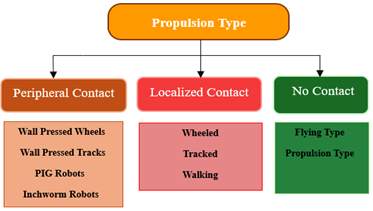
2. 2. Peripheral contact
Peripheral contact IPIRs refer to those that are fitted with mechanisms covering the complete circumferential of the interior pipeline surface. Wall pressed IPIRs require a mechanism capable of producing a traction force to press against the pipe surface, making them extremely qualified for maneuvering complex junctions [2]. Tractive force at the pipe interior surface can be performed employing wheels [3] or tracks [4]. Pipe Inspection Gauge (PIG) robots typically require the fluid medium or the pipeline to be running for it to be operational, restricting its usage for inspection. Inchworm IPIRs are quite like that of wall pressed IPIRs. However, they typically mimic the movement of an inchworm by utilizing mechanisms capable of producing a periodic expansion and compression movement [5].
2. 3. Localized Contact
Localized contact refers to those basic IPIRs that have legs fitted to the motors directly or indirectly, with simple controls typically consisting of two velocity pathways. Wheeled and tracked IPIRs commonly have two legs for sufficient stability and traction, making them unmatched considering steerability capabilities despite their simplistic nature. Tracks are used in place of wheels whenever a higher traction force is required. Walking IPIRs have numerous degrees of freedom due to their large number of legs. The idea is to mimic animalistic behavior capable of steering away from leftover fluid residue that builds up with time. To accomplish this, each leg comes with its own motors and actuators requiring precise control to ensure perfect harmony between the components, making the entire system heavy and complex [6].
2. 4. No Contact
No contact IPIRs refers to those whose propulsion mechanism has no contact or interaction along the interior pipeline surface. They are mainly composed of propeller type IPIRs that require the fluid medium to be active for operation similar to that of PIG robots. Propellers typically function by pushing the fluid, typically a liquid, backwards to generate a forward thrust that is used to propel the IPIR forward. However, their high dependency on the fluid characteristics alongside flow conditions proved to result in complex control requirements and limited operational range [7].
2. 5. IPIR Comparison
The performance of each IPIR with respect to desired features varies significantly from one type to another, with their dependencies considering their overall geometry and propulsion mechanisms. Table 1 presents a summary of how the IPIRs were classified with respect to contact type and propulsion mechanism. Table 2 displays a comprehensive performance comparison of the classified IPIRs across the most desired IPIR features.
Table 1: Classification of IPIR propulsion mechanisms.
|
Type |
Propulsion Mechanism |
Example |
|
Peripheral Contact |
Mechanisms that press against the pipe interior surface for traction |
Wall Pressed |
|
Inchworm |
||
|
PIG |
||
|
Localized Contact |
Mechanisms that are simplistic with direct fittings |
Wheeled |
|
Tracked |
||
|
Walking |
||
|
No Contact |
Mechanisms that rely on fluid dynamics with no prerequisites for contact points |
Propeller |
|
Flying |
Table 2: Performance comparison of different IPIRs across key features.
|
IPIRs |
|||||||
|
Feature |
Maneuverability |
Steerability |
Adaptability |
Velocity along x-axis |
Velocity along y-axis |
Simplicity |
Stability |
|
Wheeled |
✔✔ |
✔✔✔ |
✔ |
✔✔✔ |
✘ |
✔✔✔ |
✔✔ |
|
Tracked |
✔✔✔ |
✔✔ |
✔ |
✔✔ |
✘ |
✔✔✔ |
✔✔✔ |
|
Walking |
✔✔ |
✔✔✔ |
✔✔ |
✔✔ |
✔ |
✘ |
✔ |
|
Propeller |
✔ |
✘ |
✔ |
✔✔✔ |
✔ |
✔✔ |
✘ |
|
Flying |
✘ |
✘ |
✔ |
✔✔ |
✔✔ |
✘ |
✘ |
|
Wall Pressed |
✔✔✔ |
✔✔ |
✔✔✔ |
✔✔✔ |
✔✔✔ |
✔✔ |
✔✔✔ |
|
Inchworm |
✔✔ |
✔✔ |
✔ |
✔ |
✔ |
✔✔ |
✔✔ |
|
PIG |
✔ |
✘ |
✘ |
✔✔ |
✔✔ |
✔✔✔ |
✔✔ |
2. 6. Existing Mechanisms
The path of revolutionizing IPIRs has been paved by trying to overcome the challenges faced by IPIRs. The method of understanding what is already existing and combining, what works best with all these design variations to produce more efficient solutions have brought upon numerous creative designs.
The wall pressed IPIRs is a direct by product of researchers attempting to overcome the vertical climbing limitations imposed by the traditional wheeled IPIRs. The solution became so popularized that it deviated to a new classification type. Different mechanisms were designed to achieve the necessary traction force needed to accommodate vertical climbing. One method included the utilization of a controlled rotational cam profile at the center [8]. Other studies utilized slider crank mechanisms [9] or mechanical springs fitted along with the IPIR structure [10], to allow for both adaptability and stability.
Another credible solution involved the utilization of some form of adherent. Magnetic adherents require magnets to be placed throughout the structure to attach to the ferritic pipeline [11]. Additionally, pneumatic adhesions refer to applying the concept of vacuum and pressure differentials to create traction [12]. While the application of adhesion is simple, it comes with its unique set of drawbacks. The pipelines undergo gradual degradation with debris and obstacles building up as cyclic operation continues. This creates serious concerns with respect to surface compatibility, as any unwanted element could weaken the adhesive force, rendering it insufficient. Moreover, magnets require the pipeline to be ferritic in nature, otherwise the IPIR will be considered inoperative [13].
Deviating from mechanical mechanisms, a straightforward solution involves utilizing high number of motors for manipulating expansion and compression to provide the traction force [14]. In these robots, motors are directly mounted at the wheels [15]. However, this typically leads to high complexity, dependency on motors and controls making the system prone to errors and expensive.
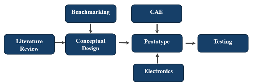
3. Methodology
The methodology chart shown in figure 2 outlines the systemic approach deployed in this paper for designing and prototyping a wall pressed wheeled IPIR. Each step represents an important milestone for efficient progression.
The first step in overcoming any obstacle is researching and understanding the problem at hand. Upon analyzing the issue, performing comparison between the theory gathered and how others approached the same issue leads in designing an innovative conceptual solution. Upon acquiring a design, prototyping step begins alongside the necessary stages needed to turn the solution into a functioning product.
3. 1. Proposed CAD Model
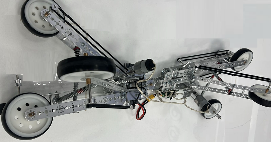
The proposed IPIR design is an eight-legged wall pressed wheeled type capable of climbing vertically through pipelines, accommodate varying diameters (10-12”) and navigate turns. It is composed of two symmetrical parts, with each part composed of six bevel gears and four wheels (4” diameter) fitted with a belt drives. Two mechanical springs and one motor provide the wheel motion for each side as shown in figure 3.
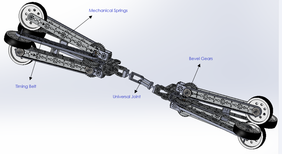
3. 2. IPIR Mechanical Design and Motion Mechanism
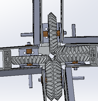
The main goal of the new IPIR design is to minimize the number of motors needed by utilizing bevel gears alongside belt drives to transfer the motion throughout the IPIR structure. A 66 rpm motor powered by a 12 V battery is used to drive the first bevel gear. The bevel gear mechanism (mounted with an angle of 90 °) transfers the motion to the remaining 3 legs as shown in figure 4. The motors are lightweight and compact, allowing sufficient torque transmissions. The driven shafts and the wheel shaft are connected by GT 2 gears, with 5 mm bore diameter and 6 mm width fitted onto a belt drive.
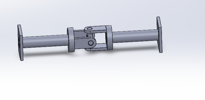
The universal joint mechanism shown in figure 5 is used to connect front and back sides together. The joint is designed via employing two pin joints connected with 90 ° orientation about their axis to prevent the IPIR from getting stuck at turns and junctions.
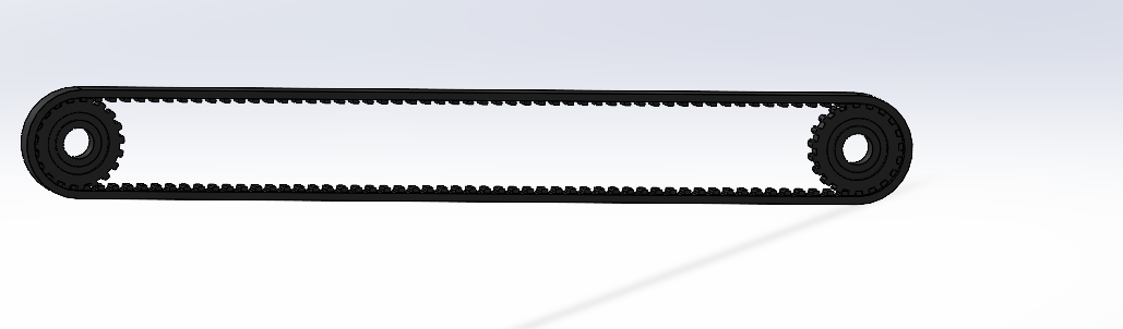
Eight belt drives are used, one for each wheel, to transfer the rotational motion of the drive shaft onto the driven wheeled shafts. Each belt configuration is unique to their respective pulley. The IPIR employs GT 2 gears with 20 teeth, 2 mm pitch and 5 mm bore diameter, and belt drives as shown in figure 6 below to meet design criteria.
The following assumptions are made during the IPIR operation for the simplicity of the calculations:
- Leg beam angles remain constant,
- Frictional force / roughness between the components is negligible,
- No power loss between the motor and the bevel gear to shaft transmission.
The design aims to keep the center of the front and back sides at the axis of the pipeline during straight motion allowing the constant and uniform leg angles. However, during prototype testing, it is observed that the robot center may deviate slightly from pipeline axis. Even in this condition, the force analysis results will be affected negligibly, as the angle deviation from the centerline will be less than 5 ° considering the structure of the robot. Additionally, within this study, the total traction force was assumed to be the weight of the robot considering the worst-case vertical climbing condition. 2 electric motors strong enough to provide the required traction are selected neglecting the losses between the motor, gears, shafts, belts and pulleys. (Assumptions 2 and 3).
3. 3. Force Analysis
The calculations are conducted at one leg for simplification since each side is symmetrical with four legs, and each leg is identical to the others. The following parameters are important upon performing force analysis on the schematic shown in figure 7.
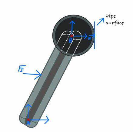
The gravitational force (W) resulting from the weight of the IPIR itself as it correlates with IPIR vertical climbing capabilities is defined as,

where m is the mass of IPIR (kg), and g is the gravitational acceleration (m/s2).
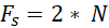
The springs provide an equivalent spring force (Fs) to the centers of all four legs. One of the springs connects the upward and downward legs and the other spring connects the left and right legs.

where k is the spring constant or spring stiffness (N/m) and is the spring deflection (m).
The traction force (Ft) ensures the IPIR does not slip and is capable of vertical climbing.
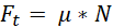
where μ is the coefficient of friction, and N is the normal force. The normal force exerted by the wheels onto the pipeline wall is the half of that of the spring force to satisfy rotational equilibrium.
To ensure the IPIR functionality, the total traction force produced must be at the very least equal to the gravitational force imposed by the IPIR weight, assuming the critical case that is 90 ° climbing with no gradual inclination.
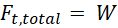
Total traction force for eight legs is equal to:
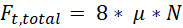
Substituting Eq. (4) and rearranging it yields:

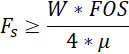
To account for an operational Factor of Safety (FOS) greater than 1, the spring force is defined as:
3.4. Structural Analysis
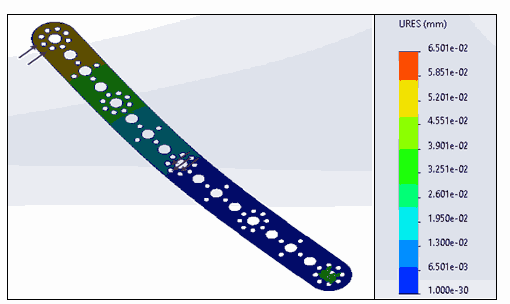
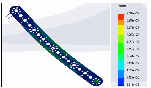
SolidWorks structural static analysis is utilized to confirm the integrity of the IPIR leg. The simulation conditions involve the forces shown in table 3, with the material chosen as aluminum alloy 1060. Forces are inputted in the direction found via force analysis calculations to study our critical component across stress, strain, displacement and FOS simulations according to Von Mises stress criteria. Note that the disfiguration shown in the figures below is exaggerated to provide clearer visual cues.
Figure 8 represents the Von Mises stress distribution across the IPIR leg, with a yield strength 2.757×10⁷ MPa. The highest stress experienced is concentrated around the applied spring force. Figure 9 represents the Von Mises FOS distribution across the IPIR leg, with a yield strength 2.757×10⁷ MPa. The minimum FOS (4.058) annotated represents the point of maximum stress.
Table 3. Minimal requirements for FOS = 1.
|
Parameter |
Value |
|
Weight of the Robot |
39.2 N |
|
Coefficient of friction for average rubber tire |
0.9 |
|
Spring force applied per leg |
10.9 N |
|
Normal Force per leg |
5.45 N |
|
Traction force per leg |
4.9 N |
The FOS is calculated by:

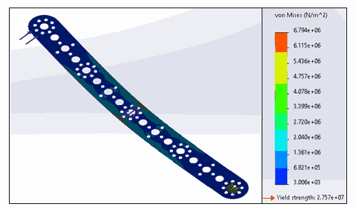 Figure 8. Von Mises stress distribution.
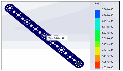
Figure 10 represents that the highest displacement experienced by the IPIR component occurred towards the top, the furthest point from the fixed pin joint which is to be expected under the loading conditions. A value of 0.065 mm represents minimal close to negligible displacement. Figure 11 represents the strain distribution experienced. The highest value of strain experienced is 7.097×10⁻⁵ and is negligible.
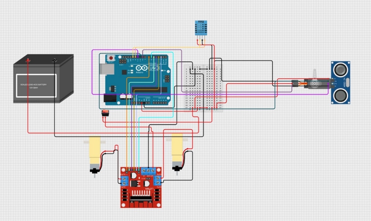
3.5. Electrical Components
The IPIR is equipped with a well-designed electronics system that facilitates smooth movement alongside data inspection and collection. Table 4 provides a detailed explanation of each component, outlining its function and technical specifications. This design ensures the robot performs efficiently and can handle a variety of inspection tasks.
Figure 12 displays the wire connections made between the Arduino board, 12V battery, the DC motors, motor controls and sensors.
3.6. IPIR Prototype
The IPIR prototype is primarily comprised of components from the advanced control robotics kit of Tetrix Robotics, however additional components such as the 66 RPM motor alongside the belt drives, gears and mechanical springs were acquired from local dealers in Kuwait.
Table 4. Detailed overview of the electronic components in the IPIR.
|
Component |
Technical Details |
Function |
|
Arduino Mega 2560 R3 |
54 digital, 16 analog inputs, USB interface for programming and provide 5V to the system |
Central processing unit; manages sensors, motors, and system logic |
|
DC Motors (JGB37-520) |
12V operating voltage, high torque, low RPM for smooth motion |
Drives the robot's movement in forward, reverse, or rotational directions |
|
Motor Driver Board |
Dual-channel motor control, overheat protection, and PWM support |
Converts control signals from the Arduino to regulate motor speed and direction |
|
HC-SR04 Ultrasonic Sensor |
Range: 2–400 cm, accuracy up to ±3 mm, ultrasonic wave technology |
Detects obstacles and calculates distance to avoid collisions |
|
DHT11 Sensor |
Temperature: 0–50°C, Humidity: 20–90%, digital output |
Measures environmental conditions within the pipe |
|
Servo Motors (SG90) |
180° rotation range, 4.8–6V operating voltage, lightweight design |
Provides controlled rotational movement for specific mechanisms |
|
LiPo Battery (3S) |
11.1V, 5200mAh capacity, lightweight and rechargeable |
Supplies stable and efficient power to all electronic components |
|
Switch |
Toggle switch with an LED indicator for visual feedback |
Manual power control for safe activation and deactivation of the robot |
|
Breadboard & Wires |
Reusable and flexible platform for circuit design and experimentation |
Connects components during prototyping and testing phases |
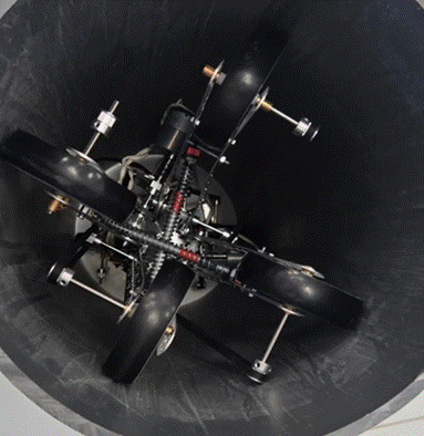
The designed IPIR is around 14’’ in the uncompressed form, utilizing the springs to facilitate the traction force required, ensuring operational capabilities along 10’’ – 12’’ pipelines.
- Mode 0: Uncompressed 14’’ IPIR, spring length: 4.92’’ (125 mm)
- Mode 1: Compressed 12’’ IPIR, spring length: 3.96’’ (100.48 mm)
- Mode 2: Compressed 10’’ IPIR, spring length: 2.92’’ (74.2 mm)
Mode 0 represents the spring neutral position, where the springs are uncompressed (Figure 13). Thus, the IPIR is considered inoperative as no traction force can be generated in this condition. Mode 1 is used for 12’’ pipelines where the IPIR can further be compressed to adjust its geometrical shape for small diameters. Mode 2 is used for 10’’ pipeline diameters, and any further compression could result in complications due to the wheels overall size (Figure 14).
3. 7. IPIR Real Life Application Restrictions
The study involves development of an IPIR that is designed to be capable of maneuvering inside 10”-12” diameter pipelines. The prototype was simply tested for straight pipes and simple 90 ° turns. However, evolving the prototype into a real-world product needs to resolve possible application field challenges such as:
- Prototype was designed to navigate inside pipeline networks with wired connection. However, the actual product should have wireless connection to resolve any loss of communication due to damage of the wires. Wireless communication quality inside metal pipes needs to be considered.
- Any oil debris left inside the pipes may affect wheels’ traction performance as friction coefficient is expected to degrade significantly. In order to deal with this situation, all four wheels were designed to rotate at the same time and speed (acting like a locked differential), therefore, slippage at one field can be compensated by the other wheels.
4. Conclusion
The development of IPIRs plays an imperative role in overcoming the challenges faced today with inspecting, maintaining and testing complex pipeline systems. The paper highlighted the different classes of IPIRs alongside their respective design, features and performances across different parameters.
A wall pressed wheeled type eight-legged IPIR that is capable of vertical climbing, maneuvering junctions, and operating within 10” to 12” diameter pipelines; was designed and the first prototype was built. Key specs of the IPIR design can be summarized as follows.
- number of electric motors was reduced to 2 (1 for each front and back side), via employing bevel gears that transfer the motion from the propulsion leg to the others,
- maneuverability of the robot was increased using the universal joint that is employed between front and back sides,
- vertical climbing traction force was provided using adjustable mechanical springs across different diameter pipelines.
SolidWorks structural mechanics analysis of the IPIR was performed for the critical leg beam component that is prone to failure under static loading conditions. Additionally, high quality electrical equipment fitted across the IPIR allows for advanced inspection capabilities.
References
[1] M. B. Trevino, Oil and Gas Pipelines, vol. 3, in Encyclopedia of Energy, vol. 3. Salem Press, Inc, 2013, p. 955.
[2] J. T. Kahnamouei and M. Moallem, "A comprehensive review of in-pipe robots," Ocean Engineering, vol. 277, p. 114260, Jun. 2023, doi: 10.1016/j.oceaneng.2023.114260. View Article
[3] G. R. Nikhade, A. K. Jha, S. Admane, P. Khandelwal, and Y. M. Sonkhaskar, "Design and Development of Cam-Operated in-Pipe Robot (CIPR)," Scientia Iranica, vol. 0, no. 0, Mar. 2024, doi: 10.24200/sci.2024.60345.6755. View Article
[4] L. Zhang and S. Meng, "Analysis of traveling-capability and obstacle-climbing capability for radially adjustable tracked pipeline robot," in 2016 IEEE International Conference on Robotics and Biomimetics (ROBIO), Qingdao, China, 2016, pp. 1748–1753, doi: 10.1109/ROBIO.2016.7866581. View Article
[5] M. Behzadfar and K.-Y. Song, "Innovative Design for Enhanced Adaptability and Performance of Soft Inchworm Robot," in 2024 4th International Conference on Computer, Control and Robotics (ICCCR), Apr. 2024, pp. 1–7, doi: 10.1109/ICCCR61138.2024.10585360. View Article
[6] A. Verma, A. Kaiwart, N. D. Dubey, F. Naseer, and S. Pradhan, "A review on various types of in-pipe inspection robot," Materials Today: Proceedings, vol. 50, pp. 1425–1434, Jan. 2022, doi: 10.1016/j.matpr.2021.08.335. View Article
[7] S. Guo, Y. Hu, J. Guo, and Q. Fu, "Design of a Novel Micro Robot In-pipe," in 2020 IEEE International Conference on Mechatronics and Automation (ICMA), Oct. 2020, pp. 1786–1791. doi: 10.1109/ICMA49215.2020.9233557. View Article
[8] G. R. Nikhade, A. K. Jha, S. Admane, P. Khandelwal, and Y. M. Sonkhaskar, "Design and Development of Cam-Operated in-Pipe Robot (CIPR)," Scientia Iranica, Mar. 2024, doi: 10.24200/sci.2024.60345.6755. View Article
[9] J. Park, T. Luong, and H. Moon, "Development of a Wheel-Type In-Pipe Robot Using Continuously Variable Transmission Mechanisms for Pipeline Inspection," Biomimetics, vol. 9, no. 2, p. 113, 2024, doi: 10.3390/biomimetics9020113. View Article
[10] A. Gargade and S. Ohol, "In-pipe inspection robot for varying pipe sizes," in Proceedings of the 6th International Conference on Intelligent Technologies (ICIT-2021), 2021, p. 19.
[11] P. A. Bogdan, J. Wheadon, F. B. Klein, and M. Gianni, "Magnetic Tracked Robot for Internal Pipe Inspection," in 2021 European Conference on Mobile Robots (ECMR), Bonn, Germany, Aug. 2021, pp. 1–6, doi: 10.1109/ECMR50962.2021.9568790. View Article
[12] G. Lee, H. Kim, K. Seo, J. Kim, and H. S. Kim, "MultiTrack: A multi-linked track robot with suction adhesion for climbing and transition," Robotics and Autonomous Systems, vol. 72, pp. 207–216, Oct. 2015, doi: 10.1016/j.robot.2015.05.011. View Article
[13] J. Jose, R. S. Elankavi, D. Dinakaran, R. M. Chetty, and M. M. Ramya, "Investigations on the magnetic adhesion properties of pipe surface inspection robot," AIP Conference Proceedings, 2022. View Article
[14] A. Gargade and S. Ohol, "In-pipe Inspection Robot for Varying Pipe Sizes," International Journal of Engineering Science, vol. 14, no. 4, 2022, doi: 10.36224/ijes.140404. View Article
[15] H. Li, R. Li, and Y. Wang, "Design and Control of In-Pipe Inspection Robot for Pre-commissioning," in Intelligent Robotics and Applications, Cham: Springer, 2021, pp. 56–66, doi: 10.1007/978-3-030-89092-6_6. View Article