Journal of Fluid Flow, Heat and Mass Transfer (JFFHMT)
ISSN: 2368-6111

Volume 12 - Year 2025 - Pages 374-380
DOI: 10.11159/jffhmt.2025.036
Study the Effect of Blade Angle on Hydrokinetic Turbine Performance
Haifa El-Sadi, Cameron Roderick, Brendan Reilly and Edmund Agyekum
1Wentworth Institute of Technology 550 Huntington, Boston, MA, USA 02115,
elsadih@wit.edu
Abstract - Harnessing renewable energy from water currents, such as rivers and tidal streams, without extensive infrastructure, positions hydrokinetic turbines as a highly promising technology. This research details the design and optimization of hydrokinetic turbine blade profiles to significantly improve their efficiency and overall performance. A comprehensive analysis, utilizing Computational Fluid Dynamics (CFD) simulations, was conducted to investigate the influence of varying angles on blade hydrodynamic performance. Our evaluation encompassed diverse blade profiles, seeking to optimize efficiency under various flow conditions, with dual objectives of maximizing power output and mitigating cavitation and structural stress. The findings conclusively demonstrate that the optimal selection of the blade angle can substantially enhance turbine efficiency, thus bolstering its potential for large-scale energy production. Furthermore, a specific angle of 67.5 degrees exhibited an unexpectedly superior power output compared to angles of 15 and 45 degrees. This work advances hydrokinetic technology and provides a robust framework for the continued optimization of renewable energy systems.
Keywords: CFD, energy, hydrokinetic turbine, blade angle
© Copyright 2025 Authors - This is an Open Access article published under the Creative Commons Attribution License terms Creative Commons Attribution License terms. Unrestricted use, distribution, and reproduction in any medium are permitted, provided the original work is properly cited.
Date Received: 2025-01-10
Date Revised: 2025-09-06
Date Accepted: 2025-09-25
Date Published: 2025-11-26
1. Introduction
The Industrial Revolution initiated an era of exponential change in energy conversion, facilitating daily life and driving engineering marvels. Yet, this progress, especially since the advent of the steam engine, has corresponded with a concerning rise in greenhouse gas emissions. Conventional hydroelectric power (HEP) has consistently proven its ability to provide significant usable clean energy globally. As of 2023, HEP stands as the leading source of low-carbon electricity worldwide, fulfilling 16% of the world's total electricity demand and playing a crucial role in reducing CO2 emissions [1]. Factors such as irregular rainfall patterns, seasonal watershed alterations, and extreme geological events are significant contributors to the fluctuation of HEP production [2]. New hydrokinetic energy facilities are planned for development in river-stream environments previously unutilized for energy production [3]. Carbon dioxide (CO2), given its high atmospheric concentration and heat-trapping properties, stands as the most significant contributor. Atmospheric CO2 levels have consequently risen exponentially, from a pre-industrial 280 parts per million (ppm) to over 379 ppm by 2005—an increase exceeding 35% [7]. To mitigate this, recent years have witnessed a global shift towards developing and adopting low-emission energy sources like nuclear, conventional hydroelectric power (HEP), wind, and tidal energy. Among these, the harnessing of hydrokinetic energy from running water uniquely represents a technology continuously refined over thousands of years. A study by Kale et al. focused on the design and optimization of Horizontal Axis Hydrokinetic Turbine (HAHT) blades. They used statistical methods like Taguchi and ANOVA to analyse experimental and computational data, which were gathered to predict the hydrodynamic performance of a HAHT [4].
Hydrokinetic energy is derived from moving water currents in rivers, ocean tides, or artificial channels. Technologies ranging from ancient waterwheels to modern horizontal axis turbines have been developed to efficiently extract this energy [5]. While conventional hydroelectric power (HEP), typically involving large dams, is the most widely utilized source of renewable energy globally, its environmental impact has spurred significant advancements. Modern HEP development prioritizes minimizing ecosystem effects by designing smaller systems that maintain or increase energy production rates. This approach is crucial for expanding clean and renewable energy utilization worldwide New hydrokinetic energy projects are being planned to harness power from river-stream applications, expanding energy production into previously undeveloped sites [3]. The selection of a specific turbine design is primarily driven by variables such as standing water height (head), site flow rate, turbine efficiency, and overall cost [6]. A direct correlation exists between flow rate, angle of attack, turbine rotational speed (RPM), and energy generation. For instance, a lower blade pitch angle typically leads to increased RPM and consequently higher energy output [8]. Ramadan et al. designed and simulated a water current Stream Energy conversion system as a stand-alone power station for the electric power generation [9]. Previous studies show that the optimized hydrokinetic turbine, named TIGRIS-27 H, is a three-bladed horizontal-axis energy converter. It rotates at 45 revolutions per minute (rpm) and generates up to 27 kW power at its rated velocity of 2.7 m/s, with an average power coefficient of 0.43 [10]. Vermaak et al. review the status of micro-hydrokinetic river (MHR) technology for rural applications. Their work aims to aid researchers in identifying areas for improvement and to encourage public bodies to implement appropriate energy policies concerning MHR technology use in rural areas [11]. Some researchers have focused on the application of hydrokinetic turbines in cold weather, indicating that such systems can provide reliable power for both micro-grids and base-load applications in remote communities located in cold climates, provided they are placed below the water surface and are not impacted by river ice floes [12].
The objective of this project is to design, build, and test a hydrokinetic turbine with different blade angles. The project will use the experimental data collected during the testing phase to validate the computational fluid dynamics (CFD) simulations.
2.Design and Manufacturing process
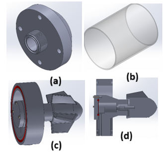
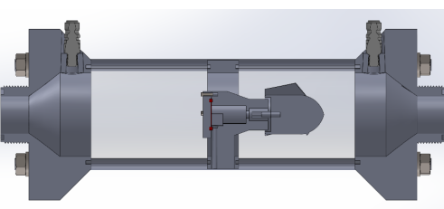
SolidWorks was utilized for the design of the experimental model's components, including the Fluid Table Fixture, transparent acrylic passage pipes, Propeller Mount, and its cross-section, as depicted in Figure 1. Figure 2 illustrates the assembled model.
The clear acrylic construction facilitates visual inspection of the internal flow dynamics and direct observation of the propeller (Figure 3) during operation. The apparatus integrates with the Gunt HM112 via two outer fixtures, which provide threaded interfaces for the water inlet and outlet connections. Two transparent acrylic passage pipes, each 80 mm in outer diameter and 100 mm in length, are robustly secured to these outer fixtures using both sealant and O-rings. The clear acrylic construction facilitates visual inspection of the internal flow dynamics and direct observation of the propeller (Figure 3) during operation. An additional set of O-rings and sealant secures the opposite ends of the passage pipes to the central propeller mount. The entire assembly is structurally reinforced by steel rods fastened with M10 hex nuts and washers at both ends (Figure 2, illustrating the complete assembly). The propeller mount (Figure 1c) itself comprises two distinct components: an outer cylindrical housing featuring a 20 mm diameter central bore on one face, and an internal passage designed for rotational motion. The propeller (Figure 3) is precisely secured through this mount to a pair of bevel gears, arranged at a 90-degree angle. This gearing mechanism efficiently translates the propeller's rotational motion to an external shaft, which directly couples to a generator. This design significantly streamlines the experimental setup by circumventing the need for generator waterproofing or the fabrication of an external waterproof housing, thereby minimizing complexity, reducing overall cost, and mitigating potential hydrodynamic inefficiencies that could otherwise compromise system performance.
The propeller itself is a Kaplan-style design featuring multiple blades, engineered to allow the blade pitch angle (referred to as Angle of blade in Figures 5a-5c for design variation) to be adjusted manually throughout testing. This propeller is attached to a 1/8-inch steel shaft that extends through the propeller mount to the first bevel gear. This shaft's motion is then translated via the bevel gears to the generator's input shaft, thus enabling the direct measurement of voltage output corresponding to the work performed by the propeller at each pre-set pitch angle.
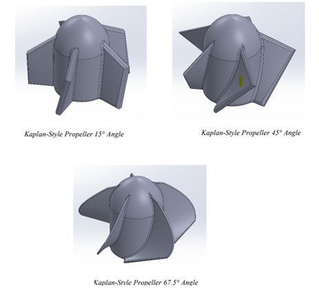
Multiple propellers were designed with distinct blade pitch angles of 15°, 45°, and 67.5°. All propellers maintained the same nominal diameter, ensuring that the blade pitch angle was the sole variable investigated across experiments. After design finalization, the non-propeller components of the apparatus were fabricated using a fused deposition modelling (FDM) 3D printer. The propellers themselves were produced via a resin-based stereolithography (SLA) 3D printer. SLA was specifically selected for propeller fabrication to ensure complete infill, thereby enhancing blade strength and minimizing deflection during operation.
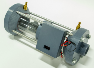
2.1 Building prototype and testing
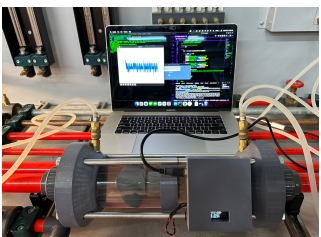
Following manufacturing, the components were assembled using epoxy for sealing and M10 mechanical hardware for structural integrity. The fully assembled apparatus, subsequently utilized for testing, is depicted in Figure 4.
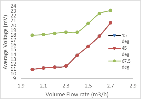
Differential pressure sensors were connected at the apparatus's inlet and exit, allowing the Flow Master device to directly output precise pressure differentials. Each of the three distinct propellers was then systematically tested across a range of input water flow rates, incrementally increasing from 2 to 2.7 m³/h in 0.1 m³/h steps. For each flow rate interval and for every propeller, the corresponding voltage output from the generator was meticulously recorded as illustrated in Figure 5. Figure 6 presents the average voltage output as a function of volume flow rate. The 67.5-degree blade pitch angle consistently produced the highest average voltage output across all tested flow rates, indicating it's likely the most efficient angle for capturing energy from the water flow. In contrast, the 15-degree and 45-degree blade pitch angles produced similar voltage outputs to each other but were less effective overall.
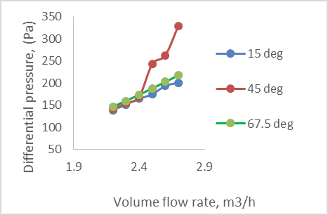
Increasing the volume flow rate raises the differential pressure of the water, which is a fundamental principle of fluid dynamics. The data shows that at a 45° blade angle, the differential pressure increases more significantly than at a 15° or 67.5° blade angle. This suggests that the 45° configuration is most effective at converting flow rate into a substantial pressure change, as shown in Figure 7. This is due to the hydrodynamic properties of the 45° blade. The angle of a blade determines how much "bite" it takes out of the water.
3. CFD Analysis
For three-dimensional, incompressible and steady state Newtonian fluid, the continuity equation and momentum equation in a rotating reference frame are:


Where ω is the angular velocity vector of the blade, r is the position vector from the axis of rotation, V is the tangential velocity. The CFD package is used to solve Navier-Stokes equations. It enables the use of different discretization schemes and solution algorithms, together with boundary conditions, volume flowrate 2-2.7 m3/h
The meshing shown in Figure 8, was executed using a solid mesh with the highest standard refinement level available in SolidWorks, using an element size of 0.035 inches. This process generated a total of 2,019,206 computational elements.
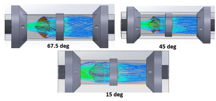
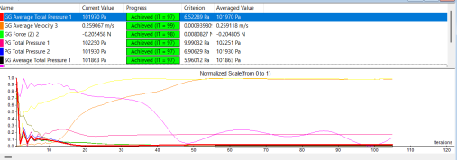
Figure 9 shows the converging graph. to ensure the highest possible accuracy of the results, additional iterations were performed beyond the initial point of convergence. By extending the computational process, even minor fluctuations in the solution were smoothed out, thereby refining the precision of the final data.
Based on the comprehensive CFD analysis, several clear conclusions can be drawn regarding the efficiencies of the propellers tested at multiple angles of attack. The study involved extensive CFD iterations to assess the performance of three different propellers with angles of 15 degrees, 45 degrees, and 67.5 degrees. Figure 10 shows the velocity contour with different angles.
4. Results and Validation
The observed outcomes are consistent with theoretical expectations, reinforcing the notion that there is a strong relationship between the input flow rate of water and the angle of blades. Specifically, as the surface area of a fin that is parallel to the flow increases, the total forces acting on the propeller also increase. This increment in force directly correlates with enhanced efficiency and higher voltage output from the hydroelectric generator. the CFD analysis has provided robust evidence that varying the angle of blade significantly impacts propeller efficiency. The 67.5-degree propeller emerged as the most efficient, highlighting the importance of optimizing fin surface area in relation to flow direction. While overly steep blade angles typically cause water flow to separate from the blade's surface, generating efficiency-reducing vortices and turbulence, the higher output at 67.5° suggests a deviation from this general behaviour. It is plausible that the confined environment of the passage pipe and the specific hydrodynamic interactions within the system prevented severe flow separation or even promoted a beneficial flow attachment unique to this geometry and operational range, thereby minimizing drag and maintaining higher efficiency. On the other hand, As the turbine rotates, the local angle of attack on the blades constantly changes. For any given turbine design and flow condition, there exists an optimal angle of attack that maximizes the lift-to-drag ratio. It is plausible that a fixed blade pitch angle of 67.5° may have, for a significant portion of the turbine's rotation cycle, aligned with or closely approximated this optimal dynamic angle of attack.
These findings contribute to the broader understanding of hydroelectric power generation and pave the way for further advancements in turbine design and optimization.
The CFD analysis showed a strong overall correlation with the experimental results, despite some localized errors. While a few areas had higher-than-expected percent errors, most of the data points fell within an acceptable range, validating the robustness of the experimental design and computational methods. Notably, the experimental force rarely exceeded the force predicted by the CFD simulations. These infrequent but significant discrepancies are a focus for future improvements to ensure the experimental setup more accurately reflects the CFD model. Specifically, the percent error ranged from 6% to 15.8% for the 67.5° propeller angle, 14% to 40% for the 45° propeller angle, and 12% to 16% for the 15° propeller angle. The observed differences between experimental measurements and CFD predictions are likely multifactorial. Key contributors include the inherent uncertainty of experimental data stemming from sensor limitations, manufacturing deviations resulting in differences between 'as-designed' and 'as-built' geometries, and the known influence of the selected turbulence model (such as k-epsilon) on simulation results.
Tables 1, 2, and 3 present a comparison of experimental and CFD-simulated force values against the volume flow rate. The data show that the percentage of error between the experimental and CFD results is lowest at a 67.5° blade angle compared to the 45° and 15° angles. This suggests the model's predictions are most accurate for the 67.5° configuration. The presence of this variation, particularly at the upper end of the spectrum, signals specific areas where the current design and experimental methodology could be enhanced. The larger deviations highlight the need for targeted improvements, such as minimizing potential sources of systematic error, refining the precision of measurement tools, and ensuring a more accurate replication of boundary conditions within the experimental setup.
Table 1. Comparison the force from Exp. and CFD vs. volume flowrate at propeller 15 degree
|
volume flowrate, m3/h |
Exp. |
CFD |
|
2.2 |
0.6 |
0.7 |
|
2.3 |
0.68 |
0.8 |
|
2.4 |
0.75 |
0.85 |
|
2.5 |
0.77 |
0.7 |
Table 2. Comparison the force from Exp. and CFD vs. volume flowrate at propeller 45 degree
|
volume flowrate, m3/h |
Exp. |
CFD |
|
2.2 |
0.45 |
0.5 |
|
2.3 |
0.68 |
0.6 |
|
2.4 |
0.8 |
0.65 |
|
2.5 |
0.9 |
0.7 |
Table 3. Comparison the force from Exp. and CFD vs. volume flowrate at propeller 67.5 degree
|
volume flowrate, m3/h |
Exp. |
CFD |
|
2.2 |
0.72 |
0.68 |
|
2.3 |
1 |
0.98 |
|
2.4 |
1.2 |
1 |
|
2.5 |
1.3 |
1.2 |
4.1 A Comprehensive Approach to Power Estimation in Variable Riverine Flows
The high-power output observed for the 67.5° blade angle in a laboratory setting is valuable as a proof of concept under idealized conditions. However, applying this result directly to a river environment is unreliable. In a river, the optimal blade angle is a complex variable influenced by site-specific factors such as flow variability, turbulence, and sediment load. Therefore, both extensive field testing and advanced computational modelling are necessary to determine the most effective blade angle for generating power in a real-world river environment. On the other hand, the optimal angle is also dependent on the specific flow velocity and characteristics of the river or tidal current. What works for a low-speed river may not be ideal for a high-speed tidal current.
5. Conclusion
Throughout the evaluation process of optimizing the angle of blades for hydrokinetic turbine blades, significant insights have been gained, leading to valuable conclusions. However, to enhance the accuracy and reliability of future analyses, several improvements have been planned. Firstly, the design of the propeller mount is slated for enhancement. The upgraded mount will incorporate a gearbox, which will enable the generator to be positioned outside the apparatus. This modification is crucial as it will minimize the risk of water intrusion into the generator, thereby improving the overall efficiency across all tested angles of blades. Secondly, the apparatus itself will be elongated to provide a smoother transition between the input connection and the inner diameter of the passage pipe. This adjustment aims to reduce turbulence and flow separation, leading to more stable and accurate data during testing. This work presents a significant anomaly in hydrokinetic turbine performance. Generally, at a high angle of blades (67.5 degrees), the propeller blades would experience severe stall, leading to a drastic reduction in power output. At 67.5 degrees, the power output might have been unexpectedly high, surpassing the power output observed at lower angles of attack, 15 and 45 degrees. It might be due to the complex hydrokinetic turbine systems, interactions between the propeller, the surrounding structure, and the flow field lead to this unexpected phenomenon. The experimental and CFD simulations demonstrated results consistent with theoretical predictions. As the angle of blades increased, the force exerted on the blades and the resulting generator rotational speed also increased. The initial hypothesis was validated, demonstrating the significant influence of blade angle on hydrokinetic turbine performance. The most notable finding was the superior performance of the 67.5° blade angle, which produced a higher power output than the 15° and 45° angles. This result was unexpected. The CFD simulations were successfully validated by experimental data, with the 67.5° blade angle showing the lowest percentage of error compared to the other angles. The observed differences between experimental measurements and CFD predictions are likely multifactorial.
References
[1] Ahialey, Kabo-Bah, and Gyamfi, "Impacts of LULC and climate changes on hydroelectric power generation and development: A systematic review," ScienceDirect, Vol. 9, Issue 11, Nov. 2023, e21247. View Article
[2] Sharma, Mishra, and Baral, "Climate change impacts on Seti Gandaki River flow from hydroelectric power perspectives, Nepal," Springer Nature Journals, Vol. 10, No. 28, 2024. View Article
[3] Uria Martinez, Rocio, and Johnson, Megan, "U.S. Hydroelectric power Market Report 2023," United States, Jan. 2023. View Article
[4] Fatih Kale, Naz Yilmaz et al., "Design and Optimization of the hydrokinetic turbine blades using statistical approaches", Journal of Renewable Energy, volume 256, 2026. View Article
[5] Anyi M., and Kirke B. "Evaluation of small axial flow hydrokinetic turbines for remote communities," Energy Sustainable Development, pp 110-116, 2010. View Article
[6] Waterpower Technologies Office, "Types of Hydroelectric power Turbines", U.S. Department of Energy, 2023.
[7] Mohajan and Hardham, "Greenhouse gas emissions increase global warming," International Journal of Economic and Political Integration, Vol. 1, No. 2, Dec. 2011.
[8] Lillahulhaq, Sandy, Mahardika, Akbar, Saragih, "Experimental study of small hydro turbine propeller performance with a variety of blade angles of attack," Sinergi, Vol. 26, No. 3, Oct. 2022 View Article
[9] A. Ramadan, Mohamed Nawar and M.H. Mohamed, "Performance evaluation of a drag hydro kinetic turbine for rivers current energy extraction- case study", volume 195, 2020 View Article
[10] Abdullah Muratoglu and M .Ishak Yuce,"Design of a River Hydrokinetic Turbine Using Optimization and CFD Simulations", volume 143, Journal of Energy Engineering. View Article
[11] Herman Vermaak, Kanzumba Kusakana and Sandile Koko, "Status of micro-hydrokinetic river technology in rural applications: A review of literature", Journal Renewable and Sustainable Energy, volume 29, 2014 View Article
[12] Woods, John, "Hydrokinetic turbine systems for remote river applications in cold climates", FGS - Electronic Theses and Practica, 2017, View Article