Journal of Fluid Flow, Heat and Mass Transfer (JFFHMT)
ISSN: 2368-6111

Volume 12 - Year 2025 - Pages 279-286
DOI: 10.11159/jffhmt.2025.027
Advanced CFD Modelling of Falling Film Evaporation on a Horizontal Tube using Sharp Interface Tracking
Yasaman Tohidi1, Scott J. Ormiston1
1University of Manitoba, Department of Mechanical Engineering
75A Chancellors Circle, Winnipeg, R3T 5V6, MB, Canada
tohidiy@myumanitoba.ca; scott.ormiston@umanitoba.ca
Abstract - This study numerically investigates the fluid flow and thermal characteristics of falling film evaporation over a horizontal tube. Water film in the vicinity of a co-current air flow flows over an isothermal tube surface. A two-dimensional two-phase laminar flow model is employed for modelling evaporation using an in-house Fortran code. A sharp interface method is used to determine the liquid gas interface. A finite volume approach was employed to discretise a set of elliptic governing equations. The results are validated against previous studies. Results, obtained from a particular test case, including film thickness, interfacial temperature, local heat transfer coefficient, and total evaporated mass are presented and discussed.
Keywords: Numerical method, Evaporation, Two-phase, Horizontal tube, Elliptic equations.
© Copyright 2025 Authors - This is an Open Access article published under the Creative Commons Attribution License terms Creative Commons Attribution License terms. Unrestricted use, distribution, and reproduction in any medium are permitted, provided the original work is properly cited.
Date Received: 2024-07-19
Date Revised: 2025-05-06
Date Accepted: 2025-05-15
Date Published: 2025-07-28
1. Introduction
Falling film evaporation plays a crucial role in facilitating heat transfer from hot surfaces and in transforming seawater into potable water through mass transfer. Film-wise evaporation is one of the most popular evaporation processes in which a thin layer of liquid that forms near a gas layer falls over the entire wall surface within a device known as a falling film evaporator. There are two common geometries used in industrial falling film applications: inside vertical channels [1], [2], [17] and over horizontal tubes [3], [4]. Horizontal tubes are widely employed geometries in industrial applications due to their ability to achieve higher heat transfer coefficients even with slight temperature variations.
2. Related Work
In the area of numerical analysis of the evaporation of a falling film over horizontal tubes, previous researchers used either CFD in-house codes or commercial software to perform the simulations. In all those studies that used a commercial code, the volume of fluid method (VOF) was utilized to find the liquid film thickness. Al-Ansari and Owen [5] performed research on the thermal and flow features of the evaporation process around a horizontal tube and the condensation process along the channel length. Using a brine falling film, they concluded that a thicker film thickness could affect the evaporation rate negatively. Moreover, they mentioned that a minimum film thickness limitation exists to avoid a dry surface. Qiu et al. [6] investigated the change of water film thickness on the surface of an adiabatic horizontal tube. They reported that the minimum film thickness is located between 90 to 140 degrees. Zhao et al. [7] used a transient solver to determine the film thickness over a horizontal tube. Proposing a correlation for the film thickness, they predicted the minimum film thickness located after 90 degrees. Qui et al. [8] simulated water and ethylene glycol falling films around a horizontal tube using a transient solver. They showed that the liquid viscosity is an important parameter affecting the falling film characteristics. Wang et al. [9] suggested a correlation for the film thickness using the ANSYS Fluent VOF 3-D model for both pure water and seawater. They found that the film thickness of the seawater film is larger in some regions due to the greater viscosity of seawater. Lin et al. [10] used a three-dimensional model to simulate flow over a horizontal tube. They used pure water as the liquid film and determined the effects of the Reynolds number on the film thickness and heat transfer coefficient. Balaji et al. [11] used a two-dimensional solution of the governing equations and a VOF approach. The liquid falling film was either pure or saline water in their study. They studied the effects of changes in the tube diameter and tube spacing on the heat transfer coefficient. Zhao et al. [12] explored the impacts of surface heat flux and liquid flow rate on the heat transfer coefficient of falling film over a horizontal tube. They revealed that the heat transfer coefficient is increasing for higher liquid flow rates. They also observed that changing the surface heat flux has negligible effects on the average heat transfer coefficient.
Some researchers experimentally investigated the evaporation process over a horizontal tube surface. Yang and Shen [13] studied evaporation for seawater and examined the impacts of the wall heat flux and salinity of seawater on the heat transfer coefficient. They found that there was a slight difference between the heat transfer coefficients of pure water and saline water. Chen et al. [14] performed experimental research on the effects of the properties of fresh and saline water on the film thickness around a horizontal tube. They observed that, for higher liquid mass flow rates, the film becomes thicker. Recently, Li et al. [15] utilized an experimental method to study the falling film evaporation of fresh water and saline water. They studied the impacts of liquid mass flow rate and salinity on the heat transfer coefficient. Additionally, they developed a correlation for the Nusselt number valid for a wide range of flow modes.
The geometry and flow dynamics of the evaporation process are complicated. The governing equations exhibit strong non-linearities and mutual dependencies between heat and mass transfer, which necessitates a robust numerical solution approach. Previous models that solved the full governing equations (elliptic approach) employed the Volume of Fluid method (VOF), which introduced an additional equation to compute the gas volume fraction in interface cells. However, a significant drawback of this method is its inability to accurately find the location of the liquid-gas interface, thereby compromising the precise application of interface jump conditions. It is evident that even though previous numerical studies have explored the heat and flow characteristics of evaporation, there is a gap in using a full elliptic model with an accurate interface modelling method for liquid and gas flow over horizontal tubes. This research employs an elliptic approach combined with an interface tracking method for simulating heat and mass transfer. The study presents and discusses results obtained from simulating a water falling film in the presence of co-current air flow.
3. Problem statement
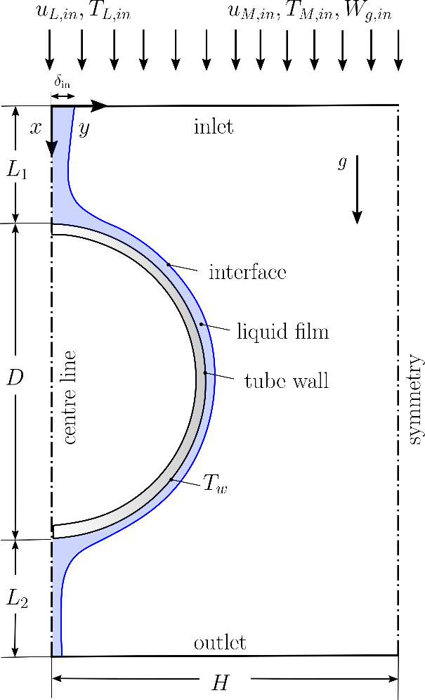
The domain of falling liquid film over a horizontal tube is shown in Figure 1. A thin liquid flows on the tube surface exposed to a uniform temperature, and a gas stream flows downwards in the vicinity of the film. As the liquid film flows over the surface, its thickness decreases due to the evaporation of the liquid. As the problem is symmetric, only a half of the tube is modelled. The tube wall region is not modelled.
4. Governing equations
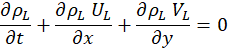
The flow is laminar, Newtonian, steady, and incompressible. The 2-D governing equations are formulated in x-y Cartesian coordinates, with x denoting the stream-wise direction and y the transverse direction. In the liquid phase, the governing system of equations can be written as follows:


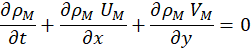
In the gas phase, the governing system of equations can be written as follows:


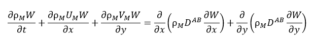
In these equations U, V, T, W, μ, Cp, ρ, DAB, k, and g denote axial velocity, tangential velocity, temperature, air mass fraction, dynamic viscosity, specific heat, density, diffusivity, conductivity, and gravity, respectively. Subscripts L and M represent liquid and gas mixture, respectively, whereas the subscripts v and g stand for vapour and gas, respectively. The local relative static pressure is denoted by P. A reference pressure (PL,in) is added to the local pressure for the properties calculation [16].
5. Boundary conditions
The boundary conditions utilized in the computational domain are:
- At the inlet (x = 0): uniform axial velocity and temperature plus zero transverse velocity in the liquid phase, and uniform air mass fraction, axial velocity, and temperature plus zero transverse velocity in the gas phase
- At the tube surface: zero slip and impermeable plus uniform temperature
- At the centre line (y = 0): zero gradient for axial velocity and temperature plus zero normal velocity in the liquid phase
- At the symmetry line (on the right side of the domain, y = H): zero gradient for temperature, axial velocity and air mass fraction plus zero normal velocity
- At the outlet (x = L1+D+L2): zero axial-direction gradient for all solution parameters
6. Interface conditions
In order to couple the liquid and gas phases at the interface (y=δ), the following conditions are utilized at the interface: normal force balance, tangential force balance, continuity of tangential velocity, continuity of temperature, impermeability of gas, energy balance, zero pressure gradient. These interface conditions have been thoroughly discussed in [2].
7. Numerical method
The computational domain includes 21 panels: 7 panels in the liquid phase and 14 panels in the gas phase. This configuration allows effective controlling of grid resolution in regions with higher gradients. The two phases are separated with an interface that is adjusted in each iteration. The initial value of the film thickness is δin everywhere in the liquid phase. The nine partial differential equations given by Equations (1) to (9) along with the given boundary and interface conditions, are solved simultaneously for the velocities, pressure, temperature in both phases and air mass fraction in the gas phase using the methodology described in [2]. After a solution is obtained on a fixed grid, the interface location is updated by using a mass balance equation on each liquid column in x-direction.
8. Grid independence study
In this study, the finest grid had the following node numbers: Ny,L = 60, Ny,M = 200, and Nx = 700, where Ny,L and Ny,M are node numbers in y-direction for the liquid and gas phase, respectively, and Nx is the node numbers in x-direction. The film thickness and interfacial temperature were compared for a couple of grids. In comparison to the finest grid, a domain with Ny,L = 30, Ny,M = 100, and Nx = 390 had the maximum percent difference of 0.13 and 0.58 for the film thickness and interfacial temperature, respectively. These variations are regarded as sufficiently small, so the above-mentioned grid was utilized in this study
9. Validation
In the present study, the results are validated through comparison with previous numerical and experimental studies [12], [14]. The working conditions of cases used for the validation purposes are summarized in Table 1, where:
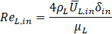
The inlet mixture Reynolds number is defined as ![]() and is set to 50 in both cases. Also, the inlet mixture temperature, TM,in, inlet reference pressure, Pref,in, and inlet gas mass fraction, Wg,in are equal to 20℃, 101.325 kPa, and 0.933, respectively, in both cases.
and is set to 50 in both cases. Also, the inlet mixture temperature, TM,in, inlet reference pressure, Pref,in, and inlet gas mass fraction, Wg,in are equal to 20℃, 101.325 kPa, and 0.933, respectively, in both cases.
Table 1. Working conditions for validation test cases.
|
Case |
D [mm]1 |
ReL,in2 |
Q''wall |
TL,in [℃]4 |
|
Chen et al. [14] |
25.4 |
184 |
0.0 |
20 |
|
Zhao et al. [12] |
12.7 |
198 |
47.3 |
46 |
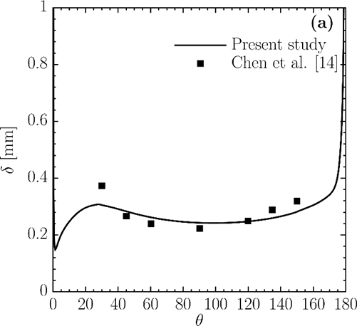
Figure 2a demonstrates the comparison of the liquid film thickness along the circumferential angle with the previous experimental study [14]. As seen in this figure, the results agree well with the experimental data. The local heat transfer coefficient compared with the numerical results presented in Zhao et al. [12] in Figure 2b. There are some differences close to the top of the tube, which can be due to the greater spatial resolution used in the code simulations. In addition, oscillations were observed in the results of Zhao et al. in that region. Over the rest of the domain, however, the present results are consistent with those in the previous numerical study. Based on the two comparisons, it is concluded that the present model reasonably represents the characteristics of the system.
10. Results and Discussion
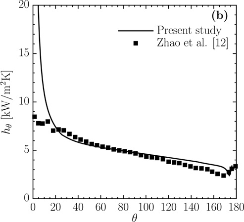
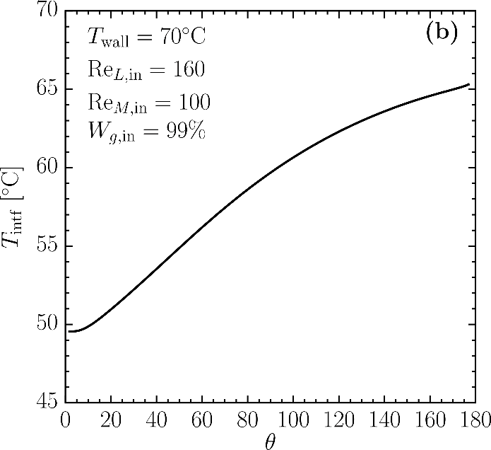
The parameters utilized in the parametric study simulation include: D=14 mm, H=114.3 mm, L1= 7 mm, L2=127 mm, ReL,in =160, ReM,in =100, TL,in =50℃ , TW =70℃ , TM,in =50℃ , Pref,in =1 atm, and Wg,in = 0.99. Figure 3a demonstrates the liquid film thickness over the circumferential angle. Film thickness is defined as the normal distance between the tube surface and liquid-gas interface; therefore, it goes to infinity at the top and bottom of the tube. For circumferential angles less than 5° , it decreases sharply, and then, it thickens up to 25°. After that, the thickness gradually decreases until reaching a local minimum value at around 100°. Figure 3b depicts the interfacial temperature along the circumferential angle. The temperature is increasing because the surface temperature is higher than that of the liquid film. Energy is transferred as sensible heat from the tube surface to the liquid film which leads to the interface temperature increase along the circumferential angle.
The local heat transfer coefficient (hθ) is calculated by the following equation:
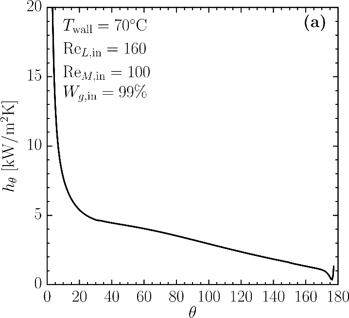
The change of heat transfer coefficient over the circumferential angle is depicted in Figure 4a. The highest heat transfer coefficient is observed at a circumferential angle less than 20° (impingement region). The heat transfer coefficient decreases steadily up to 175°. Following that, there is a slight increase observed at the lower part of the tube. This is due to the stagnation point in that region, which creates a recirculation zone in the liquid film, thereby influencing the heat transfer coefficient.
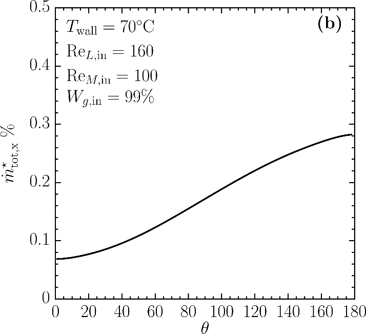
The total relative amount of evaporated water per unit depth is defined as:
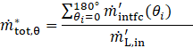
Where, ![]() is the interface mass flow rate per unit depth, and
is the interface mass flow rate per unit depth, and ![]() is the inlet mass flow rate per unit depth. Figure 4b depicts the total relative mass flow rate over the circumferential angle. As the liquid film flows over the tube surface, the mass leaves the falling film through the interface and is added to the gas phase as water vapour. For the practical applications, tube bundles are usually used instead of a single tube to maximize the amount of evaporated liquid and heat transfer in the system.
is the inlet mass flow rate per unit depth. Figure 4b depicts the total relative mass flow rate over the circumferential angle. As the liquid film flows over the tube surface, the mass leaves the falling film through the interface and is added to the gas phase as water vapour. For the practical applications, tube bundles are usually used instead of a single tube to maximize the amount of evaporated liquid and heat transfer in the system.
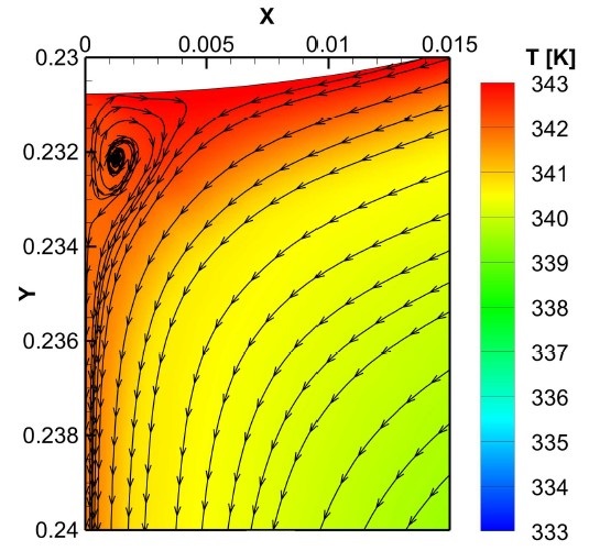
Figure 5 depicts the flow streamlines at the bottom of the tube. In this figure, the x and y axes have been scaled by dividing their values by the total length (L1+D+L2) and width (H) of the domain, respectively. As seen in this figure, a recirculation zone is formed at the lower stagnation point in the liquid film, affecting the heat transfer in that region.
11. Conclusion
A comprehensive elliptic numerical model was used for the simulation of water evaporation process over the horizontal tube surface. The solution fields were the axial and transverse velocity components, temperature, and pressure in both phases plus air mass fraction in the gas phase. Previous studies were utilized for validation of the present model.
The present results indicate that:
- A local minimum thickness of the liquid film was observed at a circumferential angle of around 100°.
- The interface temperature increases over the circumferential angle.
- The heat transfer coefficient decreases along the tube wall and shows a local increase at the lower part of the tube.
- The model is able to predict the local interface mass transfer along the circumferential angle.
The results of the present study can be used for the future design and optimization of industrial falling film evaporators. This study will help to select the operating conditions that enhance the heat and mass transfer efficiency, and it could be applied in different industrial applications such as cooling systems, desalination, and food industries, where an efficient thermal management is crucial.
References
[1] Y. Tohidi and S. J. Ormiston, "Numerical analysis of evaporation from a falling film in a vertical parallel plate channel,"International Journal of Heat and Mass Transfer, vol. 196, pp. 123282-123282, Nov. 2022, doi: https://doi.org/10.1016/j.ijheatmasstransfer.2022.123282. View Article
[2] Y. Tohidi and S. J. Ormiston, "Falling film evaporation in a partially heated parallel plate channel: Elliptic numerical analysis with an excess moisture condensation model," International Journal of Heat and Mass Transfer,vol.210, pp.124174-124174,Aug.2023,doi: https://doi.org/10.1016/j.ijheatmasstransfer.2023.124174. View Article
[3] K. Bourouni, M.T. Chaibi, and L. Tadrist, "Analytical analysis of heat transfer in liquid film dripping around a horizontal tube," Desalination, vol. 141, no. 1, pp. 7-13, Dec. 2001, doi: https://doi.org/10.1016/s0011-9164(01)00384-8. View Article
[4] G. Kocamustafaogullari and I. Y. Chen, "Falling film heat transfer analysis on a bank of horizontal tube evaporator," AIChE Journal, vol. 34, no. 9, pp. 1539-1549, Sep. 1988, doi: https://doi.org/10.1002/aic.690340916. View Article
[5] A. d. Al-Ansari and I. Owen, "Thermal and hydrodynamic analysis of the condensation and evaporation processes in horizontal tube desalination plant," International Journal of Heat and Mass Transfer, vol. 42, no. 9, pp. 1633-1644, May 1999, doi: https://doi.org/10.1016/s0017-9310(98)00240-3. View Article
[6] Q. Qiu, X. Zhu, L. Mu, and S. Shen, "Numerical study of falling film thickness over fully wetted horizontal round tube," International Journal of Heat and Mass Transfer, vol. 84, pp. 893-897, May 2015, doi: https://doi.org/10.1016/j.ijheatmasstransfer.2015.01.024. View Article
[7] C.-Y. Zhao, W.-T. Ji, P.-H. Jin, Y.-J. Zhong, and W.-Q. Tao, "Hydrodynamic behaviors of the falling film flow on a horizontal tube and construction of new film thickness correlation," International Journal of Heat and Mass Transfer, vol. 119, pp. 564-576, Apr. 2018, doi: https://doi.org/10.1016/j.ijheatmasstransfer.2017.11.086. View Article
[8] Q. Qiu, X. Zhang, S. Quan, X. Zhu, and S. Shen, "3D numerical study of the liquid film distribution on the surface of a horizontal-tube falling-film evaporator," International Journal of Heat and Mass Transfer, vol. 124, pp. 943-952, Sep. 2018, doi: https://doi.org/10.1016/j.ijheatmasstransfer.2018.04.020. View Article
[9] J. Wang, X. Chen, T. Lu, X. Chen, S. Shen, and B. Liu, "Three-dimensional film thickness distribution of horizontal tube falling film with column flow," Applied thermal engineering, vol. 154, pp. 140-149, May 2019, doi: https://doi.org/10.1016/j.applthermaleng.2019.03.041. View Article
[10] S. Lin, X. Liu, and X. Li, "The spatial distribution of liquid film thickness outside the horizontal falling film tube," International Journal of Heat and Mass Transfer, vol. 143, p. 118577, Nov. 2019, doi: https://doi.org/10.1016/j.ijheatmasstransfer.2019.118577. View Article
[11] D. Balaji, R. Velraj, and M. V. Ramana Murthy, "Numerical Investigation on the Effect of Tube Geometry and Feeder Height on the Heat Transfer Performance of Horizontal Tube Falling Film Evaporation," Journal of Heat Transfer, vol. 141, no. 11, Sep. 2019, doi: https://doi.org/10.1115/1.4044730. View Article
[12] C.-Y. Zhao, W.-T. Ji, Y.-L. He, Y.-J. Zhong, and W.-Q. Tao, "A comprehensive numerical study on the subcooled falling film heat transfer on a horizontal smooth tube," International Journal of Heat and Mass Transfer, vol. 119, pp. 259-270, Apr. 2018, doi: https://doi.org/10.1016/j.ijheatmasstransfer.2017.11.077. View Article
[13] L. Yang and S. Shen, "Experimental study of falling film evaporation heat transfer outside horizontal tubes," Desalination, vol. 220, no. 1-3, pp. 654-660, Mar. 2008, doi: https://doi.org/10.1016/j.desal.2007.02.046. View Article
[14] X. Chen, S. Shen, Y. Wang, J. Chen, and J. Zhang, "Measurement on falling film thickness distribution around horizontal tube with laser-induced fluorescence technology," International Journal of Heat and Mass Transfer, vol. 89, pp. 707-713, Oct. 2015, doi: https://doi.org/10.1016/j.ijheatmasstransfer.2015.05.016. View Article
[15] C. Li, L. Zhang, X. Mu, X. Chen and S. Shen, A correlation of heat transfer for falling film evaporation on the horizontal tube with multiple-precision expansion method, International Journal of Heat and Mass Transfer, 221 (2024), 125022, doi: https://doi.org/10.1016/j.ijheatmasstransfer.2023.125022 View Article
[16] F. Hassaninejadfarahani, M. K. Guyot, and S. J. Ormiston, "Numerical analysis of mixed-convection laminar film condensation from high air mass fraction steam-air mixtures in vertical tubes," International Journal of Heat and Mass Transfer, vol. 78, pp. 170-180, Nov. 2014, doi: https://doi.org/10.1016/j.ijheatmasstransfer.2014.06.047. View Article
[17] Y. Tohidi and S. J. Ormiston, "A two-phase sharp-interface numerical model of falling film thermal desalination in a vertical channel," Heat and Mass Transfer, vol. 61, Dec. 2024, doi: https://doi.org/10.1007/s00231-024-03527-3. View Article