Journal of Fluid Flow, Heat and Mass Transfer (JFFHMT)
ISSN: 2368-6111

Volume 12 - Year 2025 - Pages 265-278
DOI: 10.11159/jffhmt.2025.026
Impactor-Assisted Atomization in Multi-Jet Twin-Fluid Injectors for FCC Risers
Deepak Kumar1, Abhijit Kushari1, Pramod Kumar2, Hemant Mishra2
1Indian Institute of Technology Kanpur, Department of Aerospace Engineering
Kanpur, 208016, India
deepakkr@iitk.ac.in; akushari@iitk.ac.in
2Hindustan Petroleum Corporation Limited
Bangalore, India
Abstract - The Fluidized Bed Catalytic Cracking relies heavily on the atomization efficiency of the feed injection system, where vacuum gas oil is sprayed into the riser reactor for rapid vaporization and catalyst contact. This study experimentally investigates the spray behavior of a twin-fluid nozzle designed for FCC applications, focusing on the influence of air-to-liquid ratio (ALR) on droplet dynamics. Spatial measurements reveal that increasing ALR significantly reduces the section-averaged Sauter Mean Diameter (SMD) due to enhanced aerodynamic shear. The 3-hole injector consistently outperforms the 4-hole design, generating finer and more uniform droplets. Droplet size distributions exhibit lognormal behavior, with decreasing variance at higher ALRs, indicating improved spray uniformity. In contrast, axial velocity distributions deviate from normality, reflecting the influence of turbulent air–droplet interactions. The power-law correlation between SMD and ALR demonstrates that droplet breakup is primarily controlled by the air-to-liquid mass ratio and injector geometry.
Keywords: Impactor plate, Twin fluid injector, FCC Riser, SMD distribution, PDPA.
© Copyright 2025 Authors - This is an Open Access article published under the Creative Commons Attribution License terms Creative Commons Attribution License terms. Unrestricted use, distribution, and reproduction in any medium are permitted, provided the original work is properly cited.
Date Received: 2025-02-28
Date Revised: 2025-05-24
Date Accepted: 2025-06-17
Date Published: 2025-07-04
1. Introduction
Fluid Catalytic Cracking is a cornerstone process in petroleum refining, enabling the transformation of low-grade, heavy hydrocarbons into high-value products such as gasoline, olefins, and light cycle oils [2]. The FCC system comprises a riser reactor and a regenerator unit, where the feedstock—typically vacuum gas oil—is atomized and introduced at the base of the riser in the form of fine droplets. This atomization process plays a pivotal role in determining the mixing efficiency and reaction kinetics, as the liquid must rapidly vaporize and mix with the high-temperature circulating catalyst [3].
The advent of highly active zeolite-based catalysts in modern FCC systems has significantly reduced reaction residence times to just a few seconds [4], [5]. Therefore, the effectiveness of the atomization process becomes critical, especially considering the high viscosity and boiling points of heavy feedstocks. Fine atomization is required to ensure rapid and complete vaporization, which directly influences the efficiency and selectivity of the catalytic cracking reaction.
To meet these stringent performance requirements, FCC units employ twin-fluid atomizers that utilize compressed air to enhance feed dispersion. These atomizers are generally categorized into internal and external mixing types based on the location of gas–liquid interaction, and further into air-blast or air-assist modes depending on the gas flow rate and velocity. Owing to their operational robustness and adaptability to heavy feed atomization, twin-fluid injectors have been widely adopted in FCC risers for several decades.
The present investigation builds upon earlier studies [6,7] that examined the atomization performance of a newly designed twin-fluid injector and the influence of an impactor plate on spray formation. This study extends the analysis by comparing the spray characteristics of twin-fluid injectors with 3-hole and 4-hole configurations under a range of operating conditions. Using a Phase Doppler Particle Analyzer, detailed measurements of droplet size distribution and spray dynamics are conducted at various axial locations. The findings aim to provide valuable insights for enhancing injector design, with the goal of improving atomization efficiency in FCC riser applications.
2. Related Work
A significant body of literature has addressed the performance of twin-fluid atomizers in industrial and combustion applications. Guo et al. [8] demonstrated that the spray angle increases with rising liquid flow rate at a fixed gas pressure, whereas increasing the gas pressure at constant liquid flow narrows the spray cone. Chen and Lefebvre [9] observed that at low ambient pressure, the spray cone angle increases with the gas-to-liquid mass ratio (GLR), but at elevated pressures, a peak angle occurs at an intermediate GLR due to internal two-phase flow transitions.
Kushari et al. [10,11] reported that even a small air injection rate can achieve effective atomization, and emphasized that reducing the air injection area or increasing injector length leads to smaller droplet sizes. Ju et al. [12] utilized sonic compressed air (0.4 MPa) in air-assisted atomization of heavy oils, enabling fine sprays with controlled fuel flow rates. Kin et al. [13] visualized the flow structures within mixing chambers and identified that atomization primarily results from liquid film breakup along chamber walls. Nguyen et al. [14] investigated two atomizer configurations and observed droplet diameters as low as 10 µm at ALRs less than unity. They proposed a correlation linking droplet size with injector geometry and operating parameters. Kufferath et al. [15] highlighted the influence of flow regimes on radial Sauter Mean Diameter distributions, noting axial peaks in laminar flow and more uniform profiles in turbulent flow.
Karnawat et al. [16,17] evaluated twin-fluid atomizer performance under controlled laboratory conditions, while Ferreira et al. [18,19] demonstrated that increasing airflow rates decrease SMD, and identified channel diameter under choked conditions as a critical factor in achieving minimal droplet sizes. Lal et al. [20] explored controlled atomization for fire suppression applications, and Zheu et al. [21] analyzed Y-type single-hole injectors, showing that droplet size decreases non-linearly with increasing ALR. Kumar et al. [22] performed a detailed experimental study on a novel twin-fluid nozzle tailored for FCC riser applications, incorporating an impactor bolt to enhance air-liquid interaction. Their findings emphasized the effect of impactor positioning, mixing length, and slit geometry on droplet size and velocity distributions. The study confirmed that increased mixing length and optimal bolt placement significantly improve atomization quality, with minimal influence from slit size variations. Recent advances by Kumar et al. [23,24] have further explored twin-fluid atomization in FCC applications. In their study [23], the performance of a twin-fluid injector using glycerol–water mixtures were experimentally evaluated to simulate high-viscosity feed behavior, providing valuable insights into droplet size trends under varying air-to-liquid ratios. Complementing this, their work [24] investigates the influence of fluid viscosity on injector performance, emphasizing the role of rheological properties in shaping atomization characteristics.
These prior investigations underscore the complex interplay between geometry, operating parameters, and atomization quality in twin-fluid systems, motivating a focused study on multi-hole configurations for FCC applications.
3. Experimental Setup and Measurements Procedures
The MS The following subsections present a comprehensive description of the experimental facility, the design of the FCC riser injector, and the diagnostic methods used for spray characterization.
3. 1. Experimental Apparatus
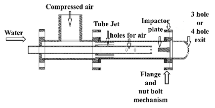
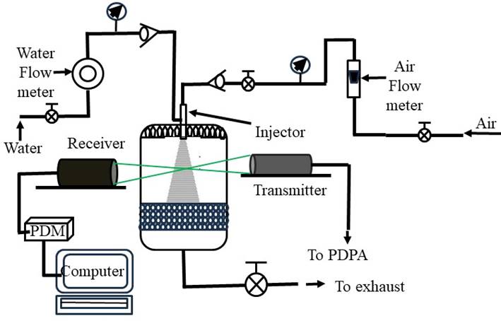
The twin-fluid atomizer used in this study is shown in Fig. 1 and comprises two nozzle configurations—one with three orifices and another with four orifices. Water and air were used as the working fluids. A 6 mm diameter central tube supplies water to the injector, with two 2 mm diameter ports at its end directing flow into the assembly. Surrounding this, a 12 mm diameter outer tube supplies air. To accelerate the airflow, a jet plate with four 1.5 mm diameter holes is installed inside the air passage. Additionally, two 2 mm diameter holes located 18 mm upstream of the central tube exit allow a small amount of air to enter the water stream, enhancing liquid acceleration. At the exit, an impactor plate induces primary breakup of the liquid jet. The resulting droplets are carried downstream by the high-speed airflow and exit through six rectangular slits (4.5 mm × 2 mm each) arranged around the impactor plate to form the spray. The fully assembled injector is mounted vertically at the top of a spray chamber (0.75 m × 0.75 m × 1.25 m), which provides optical access for PDPA measurements (Fig. 2). A honeycomb structure at the chamber base suppresses mist formation and prevents interference with the optical diagnostics. The water is supplied from a pressurized tank using compressed air, with flow controlled by a pressure regulator and monitored by a rotameter. Air is provided from a high-pressure laboratory line, regulated and monitored by a needle valve, pressure controller, and rotameter. Pressure corrections were applied using a gauge with ±1% full-scale accuracy to account for density variations.
3. 2. Test Matrix and Measurement Strategy
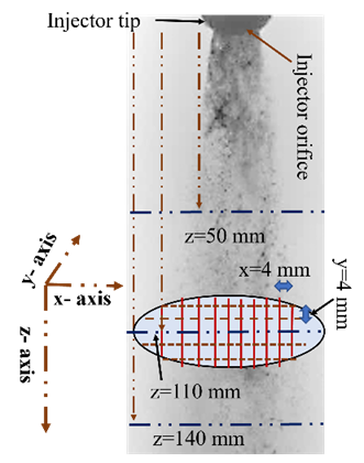
The spray characterization was conducted under independently controlled air and water flow rates to systematically evaluate the influence of operating parameters. Two water flow rates and three airflow rates were selected for each injector configuration. Detailed operating conditions for the 3-hole and 4-hole twin-fluid injectors are provided in Table 1 and Table 2, respectively. While the two injectors differ slightly in their total exit areas, the variations in flow parameters were minimal and did not significantly affect the comparative analysis. Droplet size and axial velocity were measured using a Phase Doppler Particle Analyzer at multiple axial and radial locations. Measurements were performed both along the spray centerline and across a defined transverse plane. Along the centerline, data were acquired at 10 mm intervals starting from 10 mm downstream of the nozzle exit, extending up to 180 mm. To capture the spatial distribution of the spray at a fixed downstream location, cross-sectional measurements were carried out at 110 mm from the nozzle exit over a grid spanning x = –24 mm to +24 mm and y = –20 mm to +20 mm, with 4 mm spacing in both directions. The measurement domain and grid layout are shown in Fig. 3.
Table 1. Operating Parameters for the 4-Hole Injector.
|
S. No. |
|
|
|
|
ALR |
|
1. |
0.05 |
1.1 |
0.0015 |
0.017 |
0.085 |
|
2. |
0.1 |
1.2 |
0.0015 |
0.026 |
0.058 |
|
3. |
0.1 |
2.1 |
0.0029 |
0.017 |
0.165 |
|
4. |
0.45 |
2.3 |
0.0029 |
0.026 |
0.111 |
|
5. |
0.5 |
3.7 |
0.0048 |
0.017 |
0.28 |
|
6. |
0.8 |
3.8 |
0.0048 |
0.026 |
0.19 |
 (bar)
(bar) (bar)
(bar) (kg/s)
 (kg/s)
Table 2. Operating conditions for the 3-hole injector.
|
S. No. |
Pl(bar) |
P2(bar) |
|
|
ALR |
|
1. |
0.2 |
1 |
0.0014 |
0.017 |
0.083 |
|
2. |
0.3 |
1.1 |
0.0015 |
0.026 |
0.057 |
|
3. |
0.2 |
2 |
0.0028 |
0.017 |
0.163 |
|
4. |
0.5 |
2.2 |
0.0029 |
0.026 |
0.112 |
|
5. |
1 |
3.7 |
0.0048 |
0.017 |
0.28 |
|
6. |
1.2 |
3.9 |
0.0049 |
0.026 |
0.19 |
4. Experimental Results and Discussion
This section presents a detailed analysis of the spray characteristics for the two injector configurations employed in fluidized bed catalytic cracking. The evaluation focuses on the Sauter Mean Diameter and droplet velocity distributions, which were measured both along the spray centerline and across a transverse plane. These measurements provide a comprehensive understanding of the spatial evolution of the spray, offering valuable insights into the droplet breakup and dispersion behaviour associated with each injector design.
4. 1. Axial Distribution of SMD and Velocity
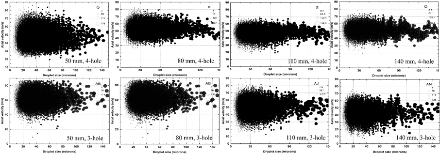
To evaluate the spray quality of both injectors, Fig. 4 illustrates the relationship between droplet size and velocity at ṁ = 0.017 kg/s and ṁ > = 0.0048 kg/s, across multiple downstream locations for the 3-hole and 4-hole configurations. Across all measurement planes, a consistent inverse trend is observed—smaller droplets tend to exhibit higher velocities, while larger droplets travel more slowly. This behavior is governed by aerodynamic drag and momentum exchange, as smaller droplets, due to their higher surface-area-to-mass ratio, decelerate more rapidly when subjected to the surrounding air. The 4-hole injector demonstrates a narrower and more uniform size distribution, with a higher concentration of fine droplets (<60 μm) and a relatively stable velocity range between 30–70 m/s. The scarcity of larger droplets indicates more effective atomization and a well-dispersed spray. As the spray travels downstream—from 50 mm to 140 mm—the overall droplet velocity decreases gradually due to continuous drag and dispersion effects.
In contrast, the 3-hole injector produces a broader range of droplet sizes and velocities, with a higher presence of large droplets (>80 μm), particularly at 110 mm and 140 mm. These larger droplets exhibit slower breakup and retain more momentum, suggesting weaker interaction with the surrounding airflow and lower atomization efficiency. Although both injectors initially generate a dense cloud of fine droplets near the nozzle (at 50 mm), the difference in spray evolution becomes more apparent further downstream. At 110 mm, the 4-hole injector continues to maintain a uniform distribution, while the 3-hole injector shows growing dominance of coarser droplets. By 140 mm, the large droplets (>100 μm) from the 3-hole injector still retain significant velocity, while in the 4-hole case, velocities taper off more smoothly—implying more efficient momentum dissipation and improved mixing.
The enhanced atomization performance of the 4-hole injector can be attributed to increased turbulence and shear intensity near the exit region, promoting finer droplet formation and more uniform dispersion. On the other hand, the 3-hole injector, having fewer discharge points, generates larger primary droplets that require longer distances to break up. As expected, smaller droplets in both cases lose velocity quickly due to higher drag, while larger droplets—especially in the 3-hole injector—retain momentum and contribute to a less uniform spray structure. Overall, the 4-hole injector achieves superior atomization through finer droplet production, consistent velocity attenuation, and a more homogeneous spray field, which are critical for enhanced mixing and combustion efficiency in FCC riser environments.
4. 2. Spatial Distribution of SMD and Velocity
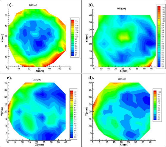
The spatial distribution of droplet Sauter Mean Diameter (SMD, D₃₂) was measured 110 mm downstream from the injector outlet for two configurations: a 4-hole injector and a 3-hole injector. Each was operated at two distinct liquid mass flow rates—0.017 kg/s and 0.026 kg/s—while maintaining a constant air mass flow rate of 0.0015 kg/s. The SMD distribution provides a direct measure of atomization quality, with lower values corresponding to finer droplets and more efficient breakup [25]. For the 4-hole injector at 0.017 kg/s (Figure 5a), the droplet field is characterized by a concentrated region of finer droplets (D₃₂ ≈ 84–98 µm) at the center, surrounded by a periphery of coarser droplets (>110 µm). This spatial variation arises from non-uniform aerodynamic shear; in the spray core, the high relative velocity between air and liquid promotes the growth of Kelvin–Helmholtz (KH) instabilities, leading to more effective atomization [26–28]. Toward the spray edges, however, the shear weakens and droplet coalescence may dominate, resulting in larger droplets. In Figure 5b, with increased liquid mass flow (0.026 kg/s), the overall SMD increases (~90–105 µm), and the size distribution becomes more uniform. This reflects a reduced air-to-liquid momentum flux ratio (q), which suppresses shear-induced breakup and increases droplet inertia, thereby limiting fragmentation [29,30].
The 3-hole injector (Figures 5c and 5d) consistently produces smaller droplets under both operating conditions. At 0.017 kg/s (Figure 5c), the SMD ranges from 40–70 µm, indicative of efficient primary breakup. This is attributed to enhanced localized shear and jet isolation due to fewer orifices and greater spacing between liquid jets, which minimizes jet–jet interaction and promotes more uniform air entrainment [31,32]. Even at the higher flow rate of 0.026 kg/s (Figure 5d), the core remains populated with fine droplets (~60–75 µm), although slightly coarser droplets (~100 µm) appear near the periphery. This shows the 3-hole injector's superior atomization stability and robustness, even when the liquid momentum is increased.
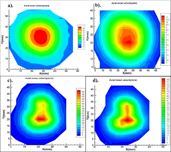
For The axial velocity distributions in Figure 6 further illustrate the coupling between aerodynamic forces and droplet dynamics. In Figure 6a, the 4-hole injector at 0.017 kg/s exhibits a peak velocity of ~9 m/s at the spray core, which decays radially outward. This pattern reflects the velocity gradient induced by air entrainment and drag, with the central zone comprising smaller droplets (Figure 5a) that accelerate more effectively [33]. As the liquid flow increases (Figure 6b), the peak axial velocity rises modestly to ~11 m/s. However, because larger droplets dominate the distribution (Figure 5b), the aerodynamic drag becomes less effective, as the droplets' higher inertia resists acceleration [34].
In contrast, the 3-hole injector shows substantially higher droplet velocities in both cases. At 0.017 kg/s (Figure 6c), the peak velocity exceeds 50 m/s, aligned with the production of fine droplets seen in Figure 5c. Smaller droplets exhibit higher surface-area-to-mass ratios, making them more susceptible to aerodynamic acceleration [35]. This efficient momentum exchange confirms that finer atomization is directly linked to greater downstream penetration. At the higher liquid flow rate (0.026 kg/s), Figure 6d still exhibits a well-focused high-velocity core (~59 m/s), demonstrating that the aerodynamic forces remain effective due to preserved droplet fineness (Figure 5d). A consistent inverse relationship between SMD and axial droplet velocity is evident across Figures 5a–d and 6a–d: regions with smaller droplets correspond to zones of higher velocity. This is consistent with fundamental fluid dynamics, where smaller droplets are more easily accelerated by air drag due to their reduced inertia and higher aerodynamic responsiveness [36]. The 3-hole injector outperforms the 4-hole design by producing finer, faster droplets under both flow conditions. This performance is attributed to geometric advantages, including better spatial jet separation and more uniform air–liquid shear zones, which improve the atomization process [31,36].
The 4-hole injector, while capable of delivering a higher total liquid mass, shows reduced performance at higher flow rates due to jet interference and inadequate shear-layer development. The deterioration in both SMD and velocity fields for the 4-hole configuration under high liquid loading emphasizes the need to balance liquid and air momentum to maintain atomization efficiency [29,37].
4. 3. Section-averaged size and velocity distribution
Figure 7 presents a comparison of the section-averaged Sauter Mean Diameter (D₃₂) as a function of the air-to-liquid mass flow ratio (ALR) for both 3-hole and 4-hole injector configurations. The results clearly demonstrate that droplet size decreases with increasing ALR for both injectors, highlighting the fundamental role of air entrainment in enhancing atomization. As the ALR increases, the relative momentum of the air stream becomes stronger, intensifying shear forces at the liquid–gas interface. This promotes the growth of Kelvin–Helmholtz instabilities, which are primarily responsible for disintegrating the liquid jets into finer droplets during the primary breakup stage. Consequently, higher ALR values lead to smaller droplet diameters, as seen in the downward trends of both curves.
Notably, the 3-hole injector consistently produces finer droplets than the 4-hole injector across the entire ALR range. This difference arises from the injector geometry and the nature of the air–liquid interaction. In the 3-hole injector, the increased spacing between jets reduces mutual interference and allows more uniform air access around each liquid jet. This leads to more efficient atomization due to better localized shear and enhanced air entrainment. In contrast, the 4-hole injector, with its denser jet arrangement, experiences greater interaction between adjacent jets, which can disrupt the airflow and lead to partial shielding or coalescence effects. As a result, the atomization efficiency of the 4-hole injector is lower, particularly at higher liquid loading or when air momentum is limited.
Additionally, the slope of the correlation curve for the 3-hole injector indicates a more sensitive response to changes in ALR, especially in the low-to-moderate range. This suggests that the 3-hole configuration utilizes the available air momentum more effectively, achieving significant reductions in droplet size even with modest increases in ALR. On the other hand, the flatter curve associated with the 4-hole injector reflects a reduced sensitivity to ALR, indicating that beyond a certain point, additional air contributes less to improving atomization. This plateau behavior likely results from saturation in local turbulence and diminished shear effectiveness once the spray becomes too dense or jet interactions dominate the flow field. Figure 7 illustrates the variation of section-averaged Sauter Mean Diameter (D₃₂) with respect to the air-to-liquid mass flow ratio (ALR) for 3-hole and 4-hole injectors. The trend demonstrates a consistent decrease in D₃₂ with increasing ALR for both configurations, confirming that greater air momentum enhances atomization by intensifying shear forces at the liquid–gas interface. Higher ALR values lead to stronger aerodynamic interactions that promote Kelvin–Helmholtz instabilities, accelerating the disintegration of liquid jets into finer droplets. This physical behavior is reflected in both the experimental data and the fitted trend lines.
To quantitatively describe this relationship, a power-law model of the form
was used, where a and b are empirical constants obtained through regression analysis. In this model, a represents the pre-exponential factor that determines the baseline droplet size, while b indicates how sensitively the droplet size responds to changes in ALR. A more negative b implies a steeper decrease in droplet size with increasing air assistance, reflecting more efficient atomization dynamics. The values of these constants differ significantly between the two injector geometries, highlighting the impact of design on atomization performance. As presented in Table 3, the 3-hole injector yields a power-law coefficient a = 18.23 and an exponent b = –0.57, with a high coefficient of determination (R² = 0.916), indicating a strong correlation between ALR and D₃₂. In contrast, the 4-hole injector exhibits a larger a = 34.73 and a less steep exponent b = –0.35, with a lower R² value of 0.71, signifying weaker sensitivity to ALR and reduced model fit. These differences align with the physical observations. The 3-hole injector, due to its wider jet spacing and improved air access, is more responsive to changes in ALR and consistently produces finer droplets across all operating conditions. The steeper slope of its fitted curve confirms that even modest increases in air flow significantly enhance droplet breakup. On the other hand, the 4-hole injector demonstrates a flatter slope and larger droplet sizes overall, suggesting limited responsiveness to increased air momentum, particularly at higher ALRs. This may be due to denser jet interactions and less effective air entrainment, which hinder the breakup process
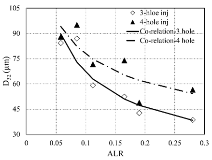
Table 3. Power-law constants and R2 for 3-hole and 4-hole injectors.
|
Injectors |
empirical constants |
|
|
|
a |
b |
R2 | |
|
3-hole injector |
18.23 |
-0.57 |
0.916 |
|
4-hole injector |
34.73 |
-0.35 |
0.71 |
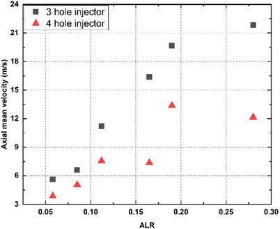
Figure 8 presents a comparative analysis of the section-averaged mean axial velocity of spray droplets for 3-hole and 4-hole injectors as a function of air-to-liquid ratio (ALR). This figure offers a dynamic perspective on spray behavior by quantifying the net forward momentum of the atomized droplets—an essential parameter that influences spray penetration, dispersion, and mixing quality in practical applications such as combustion and thermal processing. As shown in the plot, increasing the ALR leads to a clear upward trend in axial droplet velocity for both injector types, reflecting the enhanced aerodynamic interaction at higher air mass flows. However, the two configurations exhibit markedly different responses. The 3-hole injector consistently produces droplets with significantly higher axial velocities across the full range of ALR values tested. This superior velocity response highlights the enhanced air–liquid momentum coupling enabled by the 3-hole design, which allows more uniform and concentrated air flow around each jet. As a result, the finer droplets generated (as observed in earlier SMD trends) are more effectively accelerated downstream due to their lower inertia and higher surface-area-to-mass ratio. In contrast, the 4-hole injector demonstrates limited velocity gains with increasing ALR. Even at higher ALRs, the droplet velocities remain comparatively lower, plateauing around ~12–13 m/s. This behavior suggests that the additional air introduced into the 4-hole spray field does not translate efficiently into droplet acceleration. This inefficiency can be attributed to the denser jet arrangement in the 4-hole configuration, which likely results in jet crowding and disrupted airflow patterns, impeding the uniform transfer of air momentum to the droplets. Additionally, the larger droplet sizes produced by the 4-hole injector—especially under low ALR conditions—exhibit greater inertia, making them less responsive to aerodynamic acceleration. The sharper rise in axial velocity for the 3-hole injector also implies better spray penetration and deeper reach into the surrounding environment, which is particularly beneficial for applications requiring fast and uniform mixing of droplets with surrounding gas. In comparison, the flatter trajectory of the 4-hole data points suggests that beyond a certain ALR threshold, further air input yields diminishing returns in terms of droplet acceleration.
Figure 9 illustrates the section-wise probability density functions (PDFs) of droplet size distributions at a fixed downstream location for two ALR conditions, using both 3-hole and 4-hole injectors. The first two plots on the left represent the 3-hole injector, while the corresponding right-hand plots represent the 4-hole injector. These statistical distributions provide an important measure of droplet size spread and uniformity—key indicators of atomizer performance. The data reveal that, for both injector types, an increase in ALR from 0.16 to 0.19 leads to a shift in the droplet size distribution toward smaller values, as indicated by the leftward shift in the probability peaks and the corresponding reduction in Sauter Mean Diameter (SMD). More specifically, for the 3-hole injector, the SMD decreases from 52.42 µm at ALR = 0.16 to 42.71 µm at ALR = 0.19, accompanied by a reduction in variance and a tightening of the distribution. This indicates a more monodisperse spray at higher ALR, confirming that increased air momentum facilitates more uniform atomization. In contrast, the 4-hole injector shows a higher initial SMD of 71.16 µm at ALR = 0.16, decreasing to 56.48 µm at ALR = 0.19. Although the trend is consistent with that of the 3-hole injector, the absolute droplet sizes and variances are notably higher, reflecting less efficient atomization and broader size dispersion—likely due to jet interaction and weaker local shear near each orifice.
A key observation across all subfigures is that the droplet size distributions closely follow a lognormal profile, a well-documented feature of sprays resulting from fragmentation processes governed by multiplicative random effects during jet breakup. The fitted lognormal curves (in red) closely match the experimental data (in purple), validating the use of lognormal models for describing size statistics in twin-fluid atomizers. This behavior is further supported by the quantitative statistics provided in Tables 4 and 5, which summarize the mean diameter, SMD, variance, and lognormal parameters (μ and σ) for a range of ALR values. For the 3-hole injector (Table 4), SMD decreases significantly from 84.3 µm at ALR = 0.05 to 42.71 µm at ALR = 0.19.
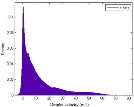
This sharp reduction is accompanied by a notable drop in variance (from 603.71 to 144.43) and a decreasing σ, indicating a narrower and more uniform spray. Interestingly, while the mean size decreases with increasing ALR, the value of μ remains relatively consistent (~2.86–3.16), suggesting a stable distribution center in logarithmic space, while σ governs the spread. In contrast, Figure 10 presents the corresponding axial velocity distribution for the droplets at the same plane. Unlike the droplet size distributions, the velocity profile does not conform to any conventional statistical model, such as Gaussian or lognormal. The data exhibit multiple peaks and a highly asymmetric shape, indicating complex, nonuniform momentum transfer processes. This irregularity can be attributed to the interaction of droplets with turbulent air structures, local recirculation zones, and varying degrees of aerodynamic acceleration—factors that are inherently chaotic and sensitive to local conditions within the spray field.
These findings support the broader conclusion that ALR significantly influences not just droplet size, but also its distribution characteristics, while velocity fields require more detailed spatial and temporal resolution for accurate statistical modelling.
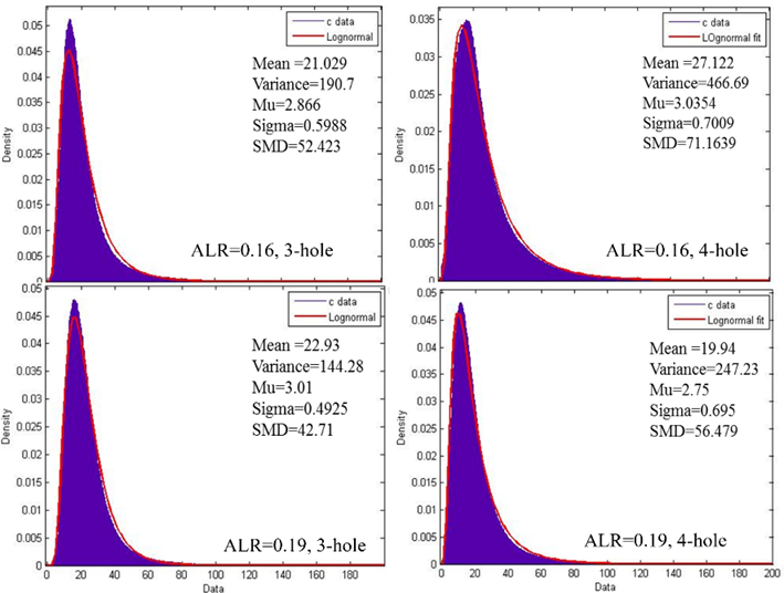
Table 4. Summary of section-wise averaged mean size, SMD, μ, and σ for 3-hole injector 1.
|
ALR |
Mean |
SMD |
σ |
µ |
variance |
|
0.05 |
27.69 |
84.3 |
3.03 |
0.76 |
603.71 |
|
0.08 |
25.35 |
86.12 |
2.91 |
0.81 |
587.23 |
|
0.11 |
26.88 |
53.16 |
3.16 |
0.49 |
202.44 |
|
0.16 |
21.03 |
52.42 |
2.86 |
0.59 |
190.71 |
|
0.19 |
22.31 |
42.71 |
3.01 |
0.49 |
144.43 |
Table 5. Summary of section-wise averaged mean size, SMD, μ, and σ for 4-hole injector.
|
ALR |
Mean |
SMD |
σ |
µ |
variance |
|
0.05 |
31.07 |
95.07 |
3.07 |
0.86 |
1055.1 |
|
0.08 |
31.66 |
88.02 |
3.14 |
0.78 |
864.67 |
|
0.11 |
34.26 |
73.92 |
3.35 |
0.61 |
517.38 |
|
0.16 |
27.12 |
71.16 |
3.05 |
0.71 |
466.67 |
|
0.19 |
19.94 |
56.47 |
2.75 |
0.69 |
247.23 |
5. Conclusion
A twin-fluid atomizer featuring an impactor plate was developed and experimentally assessed for application in modern FCC riser systems. Two nozzle configurations—one with three discharge orifices and another with four—were evaluated to investigate the effects of geometric variation on atomization behavior. Detailed droplet size and velocity measurements were carried out using Phase Doppler Particle Analyzer (PDPA) at various downstream locations under different air-to-liquid ratios (ALRs). The conclusions are as follows:
- The 4-hole injector demonstrated better atomization performance, producing finer and more uniformly distributed droplets, resulting in a more homogeneous spray field suitable for efficient gas–liquid mixing in FCC riser environments.
- The 3-hole injector generated larger droplets with higher axial velocities but exhibited less uniformity and broader velocity distributions, indicating delayed breakup and reduced atomization efficiency.
- For both injectors, the maximum droplet velocity was observed along the spray centerline and decreased radially outward due to momentum loss and aerodynamic drag.
- Small droplets exhibited higher axial velocities and negligible radial components, while larger droplets showed increased radial velocities and lower axial velocities, highlighting the size-dependent aerodynamic response.
- At constant water flow rate, increasing air mass flow rate led to higher droplet velocities and reduced Sauter Mean Diameter (SMD), emphasizing the dominant role of air kinetic energy in the atomization process.
- At constant air mass flow rate, increasing the water flow rate caused a moderate increase in SMD with little change in droplet velocity, indicating a reduced breakup efficiency under liquid-dominant conditions.
- For the same ALR, the 3-hole injector—with a smaller total exit area—produced higher droplet velocities and lower SMD compared to the 4-hole configuration, suggesting increased local shear and turbulence near the discharge region.
- Section-averaged analysis at 110 mm downstream showed that SMD decreased and mean axial velocity increased with rising ALR for both injector types.
- The droplet size distribution across the spray section followed a lognormal trend, while velocity distribution showed no specific statistical pattern.
Overall, the study confirms that injector geometry, flow rate conditions, and air-to-liquid ratio significantly influence atomization quality. The 4-hole configuration offers more efficient spray characteristics, whereas the 3-hole design yields coarser atomization and greater variability, making it less favorable for uniform mixing in FCC riser applications
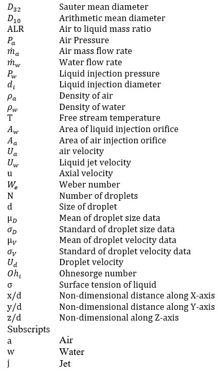
Nomenclature
References
[1] A. H. Lefebvre, Atomization and Sprays. New York: Hemisphere Publishing Corporation of Taylor & Francis, 1989.
[2] P. B. Venuto and E. T. Habib, Fluid Catalytic Cracking with Zeolite Catalysts. New York: Marcel Dekker, 1979.
[3] K. N. Theologos, A. I. Lygeros, and N. C. Markatos, “Feedstock atomization effects on FCC riser reactors selectivity,” Chem. Eng. Sci., vol. 54, no. 22, pp. 5617–5625, 1999. View Article
[4] C. Mirgain, C. Briens, and M. D. Pozo, “Modeling of feed vaporization in fluid catalytic cracking,” Ind. Eng. Chem. Res., vol. 39, no. 11, pp. 4392–4399, 2000. View Article
[5] A. Gupta and D. S. Rao, “Model for the performance of a fluid catalytic cracking (FCC) riser reactor: Effect of feed atomization,” Chem. Eng. Sci., vol. 56, no. 15, pp. 4489–4503, 2001. View Article
[6] D. Kumar, T. Sikroria, A. Kushari, P. Kumar, and G. Sriganesh, “A twin-fluid injector for FCC feed injection,” Int. J. Petrochem. Sci. Eng., vol. 4, no. 3, pp. 109–115, 2019. View Article
[7] D. Kumar, T. Sikroria, A. Kushari, P. Kumar, and G. Sriganesh, "Spray characteristics from a twin-fluid atomizer with internal impactor" ILASS-Asia 2016, 18th Annual Conference on Liquid Atomization and Spray Systems - Asia, Chennai, India. 6- 9 Nov. 2016.
[8] L. J. Guo, G. J. Li, B. Chen, X. J. Chen, D. D. Papailiou, and Th. Panidis, “Study on gas-liquid two-phase spraying characteristics of nozzles for the humidification of smoke,” Exp. Therm. Fluid Sci., vol. 26, pp. 715–722, 2002. View Article
[9] A. H. Lefebvre and J. S. Chin, “Flow patterns in internal-mixing, twin-fluid atomizers,” Atomization Sprays, vol. 3, no. 4, pp. 463–475, 1993. View Article
[10] A. Kushari, Y. Neumeier, O. Israeli, E. Lubarsky, and B. T. Zinn, “Internally mixed liquid injector for active control of atomization process,” J. Propul. Power, vol. 17, no. 4, pp. 878–882, 2001. View Article
[11] A. Kushari, “Effect of injector geometry on the performance of an internally mixed liquid atomizer,” Fuel Process Technol., vol. 91, no. 11, pp. 1650–1654, 2010. View Article
[12] S. C. Ju and X. W. Li, “Experimental study on internal mixing sonic flow air assist atomizer for heavy oils,” in Proc. Int. Gas Turbine and Aeroengine Congress and Exposition, Brussels, Belgium, Jun. 11–14, 1990, ASME, Paper T6.
[13] S. Kim, S. Kondo, K. Nishida, and H. Hiroyasu, “Effects of mixing chamber geometry and flow on spray characteristics from an internal mixing twin-fluid atomizer,” Int. J. Fluid Mech. Res., vol. 24, no. 1–3, pp. 76–87, 1997. View Article
[14] D. A. Nguyen and M. J. Rhodes, “Producing fine drops of water by twin-fluid atomisation,” Powder Technol., vol. 99, no. 3, pp. 285–292, 1998. View Article
[15] A. Kufferath, B. Wende, and W. Leuckel, “Influence of liquid flow conditions on spray characteristics of internal-mixing twin-fluid atomizers,” Int. J. Heat Fluid Flow, vol. 20, no. 5, pp. 513–519, 1999. View Article
[16] J. Karnawat and A. Kushari, “Controlled atomization using a twin-fluid swirl atomizer,” Exp. Fluids, vol. 41, no. 4, pp. 649–663, 2006. View Article
[17] J. Karnawat and A. Kushari, “Spray evolution in a twin-fluid swirl atomizer,” Atomization Sprays, vol. 18, no. 5, pp. 449–470, 2008. View Article
[18] G. Ferreira, F. Barreras, A. Lozano, J. A. Garcia, and E. Lincheta, “Effect of the inner twin-fluid nozzle with an internal mixing chamber,” Atomization Sprays, vol. 19, no. 9, pp. 873–884, 2009. View Article
[19] G. Ferreira, J. A. Garcia, F. Barreras, A. Lozano, and E. Lincheta, “Design optimization of twin-fluid atomizers with an internal mixing chamber for heavy fuel oils,” Fuel Process Technol., vol. 90, no. 2, pp. 270–278, 2009. View Article
[20] S. Lal, A. Kushari, M. Gupta, J. C. Kapoor, and S. Maji, “Experimental study of an air-assisted mist generator,” Exp. Therm. Fluid Sci., vol. 34, no. 8, pp. 1029–1035, 2010. View Article
[21] L. Broniarz-Press, M. Ochowiak, J. Rozanski, and S. Woziwodzki, “The atomization of water-oil emulsions,” Exp. Therm. Fluid Sci., vol. 33, no. 6, pp. 955–962, 2009. View Article
[22] D. Kumar, A. Kushari, P. Kumar, and H. Mishra, “Droplet Size Distribution in Twin Fluid Nozzle for Modern FCC Riser,” Journal of Fluid Flow, Heat and Mass Transfer, Vol. 11, pp. 363–375, 2024. DOI: 10.11159/jffhmt.2024.036. View Article
[23] D. Kumar, A. Kushari, P. Kumar, and H. Mishra, “Twin Fluid Injector for FCC Feed Injection: A Performance Analysis with Glycerol Mixtures,” Proc. 16th Triennial International Conference on Liquid Atomization and Spray Systems (ICLASS 2024), Shanghai, China, 2024.
[24] D. Kumar, A. Kushari, P. K. Singh, and P. Kumar, “Effect of Viscosity on the Performance of Twin-Fluid Injector for Modern FCC,” in Recent Trends in Thermal and Fluid Sciences, A. Singh, D. P. Mishra, and G. Bhat, Eds., Lecture Notes in Mechanical Engineering, Springer, Singapore, 2024. View Article
[25] A. H. Lefebvre and V. G. McDonell, Atomization and Sprays, 2nd ed., CRC Press, 2017. View Article
[26] J. C. Lasheras and E. J. Hopfinger, “Liquid Jet Instability and Atomization in a Coaxial Gas Stream,” Annu. Rev. Fluid Mech., Vol. 32, pp. 275–308, 2000. View Article
[27] G. M. Faeth, “Current Status of Droplet and Liquid Combustion,” Prog. Energy Combust. Sci., Vol. 3, pp. 191–224, 1977. View Article
[28] S. P. Lin and R. D. Reitz, “Drop and Spray Formation from a Liquid Jet,” Annu. Rev. Fluid Mech., Vol. 30, pp. 85–105, 1998. View Article
[29] C. H. Wang, X. Liu, and C. K. Law, “Flame Propagation and Structure in Stratified Mixtures,” Combust. Flame, Vol. 96, pp. 217–232, 1994.
[30] E. Villermaux, “Fragmentation,” Annu. Rev. Fluid Mech., Vol. 39, pp. 419–446, 2007. View Article
[31] L. Zhou, et al., “Experimental Study on Atomization Characteristics of a Pressure-Swirl Atomizer,” Exp. Therm. Fluid Sci., Vol. 83, pp. 123–131, 2017.
[32] H. Ghassemi and N. Ashgriz, “Breakup of Planar Liquid Jets in High-Speed Gas Streams,” Atomization and Sprays, Vol. 6, No. 3, pp. 289–306, 1996.
[33] N. K. Rizk and A. H. Lefebvre, “Structure of Atomizing Airblast Sprays,” J. Propul. Power, Vol. 1, No. 3, pp. 193–199, 1985. View Article
[34] G. G. Nasr, A. J. Yule, and L. Bendig, Industrial Sprays and Atomization, Springer, 2002. View Article
[35] J. K. Dukowicz, “Quasi-Steady Drop Formation from a Liquid Jet,” J. Comput. Phys., Vol. 35, pp. 229–253, 1980. View Article
[36] H. Liu, Science and Engineering of Droplets, William Andrew Publishing, 2000.
[37] G. Sovran and T. A. Newton, “Design Considerations for High-Speed Twin-Fluid Atomizers,” ASME J. Eng. Gas Turbines Power, Vol. 128, pp. 678–686, 2006.
[38] A. Lozano, F. Barreras, and A. Liñán, “Analysis of the Primary Atomization Region in Pressure-Swirl Atomizers,” Atomization and Sprays, Vol. 12, pp. 403–426, 2002.