Journal of Fluid Flow, Heat and Mass Transfer (JFFHMT)
ISSN: 2368-6111

Volume 12 - Year 2025 - Pages 242-250
DOI: 10.11159/jffhmt.2025.024
Numerical Investigation of Hybrid Immersion Cooling Strategies for Battery Packs in Light Electric Vehicles
Stefano Landini1, Jack Panter1,Anindita Roy2, Gordhan Das Valasai3, Mohammad Fawzi Ismail4
1School of Engineering, Mathematics and Physics, University of East Anglia, NR4 7TJ, Norwich UK
s.landini@uea.ac.uk; j.panter@uea.ac.uk
2Mechanical Engineering Department, Symbiosis Institute of Technology, Symbiosis International (Deemed) University, Pune 412115, India
anindita.roy@sitpune.edu.in
3Department of Mechanical Engineering, Quaid -e- Awam University of Engineering, Science and Technology, Sakrand Road, Nawabshah, Shaheed Benazirabad, Sindh 67450, Pakistan
valasai@quest.edu.pk
4 Department of Renewable Energy Engineering, Amman Arab University, Amman, Jordan
m.ismail@aau.edu.jo
Abstract - This work investigates a new hybrid thermal management system (TMS) for light electric vehicle (LEV) battery packs that uses dielectric liquid immersion cooling, heat pipes and fins to effectively control lithium-ion battery (LIB) thermal load. Different commercial dielectric oil chemistries (Cargill DE-11772 and EF-3221, LK-STO50, and MIVOLT-DFK) are evaluated as heat transfer fluids (HTFs) and compared with air and deionised water as benchmark. Additionally, the effects of heat pipe diameters (4 mm, 6 mm, and 8 mm) and the number of fins (1, 2, 3, and 5) are analysed for two configurations: fins evenly distributed along the heat pipe and fins placed only on the upper half. A 3D steady-state CFD model is developed in Ansys 2024R2 to simulate the proposed TMS for a 4S4P (14.8V, 10 Ah) Lithium-Nickel Manganese Cobalt (NMC) battery pack. Under typical 2C discharge rate, the model examines the TMS thermal performance when simulating heat transfer with and without buoyancy effects. Buoyancy improves cooling performance, especially for viscous fluids, lowering battery, HTF, and heat sink temperatures by 20%. With modest LIB heat generation rates (up to 25 kW/m³), the TMS ensures effective cooling with minimum temperature increase. However, when reaching heat generation rates up to 100 kW/m³, the battery temperature reaches 91.13°C, revealing the system's cooling capability limitations. The study examines the effect of changing heat sink and insulation equivalent convective heat transfer coefficients. Increasing the heat sink coefficient from 10 to 100 W/m²K lowers the battery temperature from 138°C to 49°C, while increasing the insulation equivalent heat transfer coefficient from 1 to 50 W/m²K lowers battery temperature from 92°C to 46°C. Also, the effect of heat pipes diameter and fins number and vertical distribution is analysed, pointing to the design with 5 evenly distributed fins to be the best thermally performing while limiting additional TMS mass. This study shows that the hybrid TMS using heat pipes, fins,immersionfins, immersion cooling improves compact LEV safety, performance, and battery longevity under high-demand situations.
Keywords: Lithium-ion batteries, Light electric vehicles, Thermal management, Immersion cooling.
© Copyright 2025 Authors - This is an Open Access article published under the Creative Commons Attribution License terms Creative Commons Attribution License terms. Unrestricted use, distribution, and reproduction in any medium are permitted, provided the original work is properly cited.
Date Received: 2025-02-24
Date Revised: 2025-05-15
Date Accepted: 2025-06-02
Date Published: 2025-06-11
Nomenclature
1. Introduction
Lithium-ion batteries (LIBs) power electric vehicles (EVs) due to their high energy storage capacity, low mass, and extended lifespan. The efficiency and safety of such devices are susceptible to temperature changes. Thermal runaway occurs when the battery temperature rises uncontrolled, posing a danger of fire or explosion that can only be prevented by a thermal management system (TMS). Due to high discharge rates (DR) and battery pack conditions, including high heat, EVs and other high-power applications have that problem. Besides being safe, the components are properly shielded, and the battery lasts longer and performs better [1, 2].
Since LIBs are widely utilised in EVs, innovative cooling techniques for thermal load management have been extensively studied. Though inefficient at high power utilisation, conventional air-cooling solutions are more popular due to their simplicity. Specifically in two-wheeled EVs, the space available for an intricate cooling mechanism is insufficient, therefore effective compact light TMS are needed. Researchers have developed PCMs, passive and active liquid cooling, and hybrid cooling methods to address these issues. Fluid chemistry, flow rate, ambient temperature, and battery configuration affect fluid efficacy and cooling performance. By optimising battery pack temperature and eliminating thermal gradients, a well-designed TMS may improve LIB safety, performance, and lifespan [3, 4].
Air cooling is one of the simplest and most affordable ways for controlling LIB temperature. It broadly consists in blowing air across the battery cells to remove the generate heat during operation. Misar and Thombre [5] analysed the application of high-thermal-conductivity potting material along with air cooling to a 3S3P NMC 21700 battery pack in electric two-wheelers. This configuration was discovered to lower temperature variation by a quarter, enhancing temperature uniformity within the battery pack. In a similar manner, Zhang, et al. [6] also worked on airflow control in an air cooled LIB pack observing that altering the position of the air cooling channel exit led to reduced maximum temperature and thermal non-uniformity with improvement under 2C discharge rates.
Liquid cooling systems use a coolant, e.g. mixture of water or water glycol, which flows through conduits interior or exterior of the battery pack to remove heat. Suresh Patil, et al. [7] compared water-glycol cold plate cooling with dielectric fluid immersion cooling of a 50 V LIB pack. This proved that the immersion cooling system was capable to reduce the maximum temperature by 9.3% during high discharge rates (up to 5C) more than the water-glycol cooling technique. Additionally, Wu, et al. [8] also pointed other modern challenges noting that higher flow rates of coolants result in excessive energy consumption without a proportional improvement of cooling. Nonetheless, Wu, et al. [8], and Liu, et al. [9] highlighted that the water-glycol mixtures and other liquid coolants can deliver lower maximum temperature in high-rate discharge.
Immersion cooling consists in the entire battery pack being submerged in a dielectric (non-electrically conductive) heat transfer fluid (HTF) which absorbs heat and dissipates it by natural buoyancy-driven convection cells into a heat sink. This method is particularly effective to avoid concentration of heat (thermal hotspots) and cool all the surface of the battery uniformly including the tabs, so it is suitable for high power and/or high energy density LIB. Thiru Kumaran and Hemavathi [10] proved that the maximum temperature of a 50 V LIB pack under 3C discharges could effectively drop by 35.95% if using dielectric fluid immersion cooling, thus preventing thermal runaway. Williams, et al. [11] also independently confirmed the usability of Novec 7000 dielectric fluid to keep the thermal difference below 1°C across a 26650 LiFePO4 cylindrical cell module charging at up to 4C rate. As Thiru Kumaran and Hemavathi [10] and Williams, et al. [11] stated, when mineral oil and Novec 7000 dielectric fluids were used, battery temperatures reduced, and temperature differences in the battery modules were measured minimally. Liquid dielectrics minimise electrical short circuits and offer uniform cool flow rates and heat dissipation without electric conductivity.
Novel interest in the research community is now focusing on combination of cooling systems to enhance thermal performance and reduce volumes, weight, and cost. The latter is typically achieved by constraining the TMS mechanism to be based on passive heat transfer. Zou, et al. [12] recently investigated a dual-cooling system which incorporated static liquid immersion and liquid forced convection tubes. This system was able to lower the maximum temperature of battery module to 43.3°C when discharging at a rate of 3C at an ambient temperature of 25°C. Wang, et al. [13] proved that by using both immersion and direct forced convection cooling method, safe LIB operation time below 35°C was extended by 150% compared to air natural convection. Wang, et al. [14] investigated two-phase dielectric liquid immersion cooling integrated with forced air-cooling. The hybrid system was shown to be effective in enhancing temperature uniformity under during high-rate discharges. Similarly, in Liu, et al. [15] and Zhu, et al. [16], it was demonstrated that the use of multiple cooling techniques would help to enhance the overall regulating ability and safety.
From the revised literature, there is evidence of limited research efforts on developing light compact cost-effective TMS for two-wheeled EVs and light electric vehicles (LEVs), which are gaining steeply popularity across cities in all continents, especially EU and Asia. In these applications, air-cooled systems, whether natural or induced convection, are currently adopted due to spatial constraints and the complexities associated with indirect liquid cooling systems. However, these TMS are proved to be inadequate for maintaining optimal temperature control independent of environmental conditions. Therefore, this research aims to evaluate the feasibility of a novel hybrid passive LIB TMS that integrates dielectric liquid immersion cooling with heat pipes and various fins configurations, specifically tailored for electric two-wheeler applications. A numerical investigation was conducted on different prototypes of this hybrid immersion cooling system, which operates without HTF circulation.
2. Methodology
1. 1. Geometry
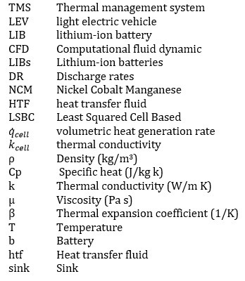
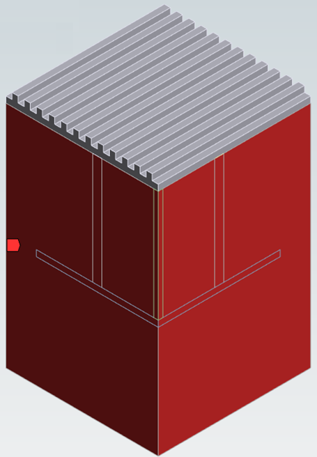
This study included the design and thermal performance evaluation by CFD numerical analysis of a single-phase immersion cooled battery pack equipped with heat pipes, fins, and topping heat sink for rapid heat dissipation. A benchmark prototype (Figure 1) is based on a typical 2-wheeler 4S4P (4 series, 4 parallel) 14.8V 10 Ah Lithium-Nickel Manganese Cobalt (NMC) oxide LIB, where cylindrical cells are typically preferred being more readily available, less expensive, and easier to assemble. The properties of the NMC LIB are reported in Table 1. All numerical simulations conducted where based on a steady-state operating condition and a discharge rate of 2C. This represents a stress condition of 2-wheeler EV battery pack.
The aim was to examine the effectiveness of immersion cooling with different HTF (air, de-ionised water, four commercial dielectric oils) and different TMS components configurations (heat pipes and fins configurations). All these cases were compared with the simplest TMS design where the LIB cells are placed within the same enclosure (same volume, without topping heat sink) filled with either air or pristine dielectric oil.
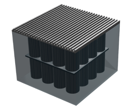
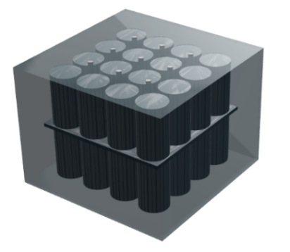
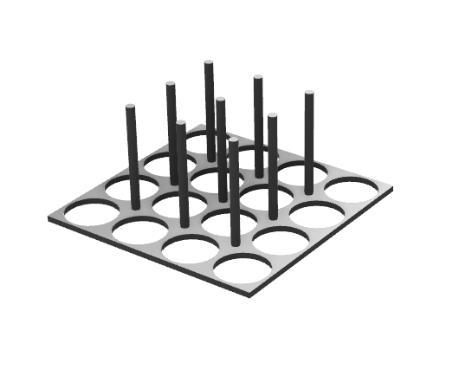
CFD models of the TMS, including LIB cells, fins, heat pipes, heat sink, and HTF were created on ANSYS (2024 R2) to simulate the physics and evaluate the performance of the proposed LIB TMS. Figure 1 shows the benchmark TMS design proposed including HTF, a single fin, nine heat pipes (4-mm diameter), and a topping heat sink.
Table 1: Thermophysical properties of LIB NMC 18650 cells
|
Parameter |
Value |
|
Diameter [mm] |
18 |
|
Height [mm] |
65 |
|
Nominal capacity [Ah] |
2.5 |
|
Nominal voltage [V] |
3.7 |
|
Min/Max cut-off voltage [V] |
2.8 / 4.8 |
|
Cathode/Anode Chemistry |
NMC Graphite |
|
Density [kg/m3] |
2,000 |
|
Specific Heat Capacity [J/kg K] |
1,000 |
|
Radial Thermal Conductivity [W/m K] |
1 |
|
Axial Thermal Conductivity [W/m K] |
30 |
2. 2. Computational Fluid Dynamics Modelling
All simulations were based on a constant LIB cells’ volumetric heat generation rate of 100 kW/m3 based on experimental evidenced gathered, representative of a standard 2C discharge rate for 18650 LIB NMC cells. Within the cell body, only the energy balance is solved (Equation 1), where kcell stands for the effective anisotropic thermal conductivity (W/mK), and q'cell denotes the volumetric heat generation rate (W/m3) of the battery. Direction determines the LIB cell's effective thermal conductivity kcell, which is 1 W/m K in the radial direction and 30 W/mK in the axial direction, as reported in Table 1.

Within the HTF body, continuity, momentum and energy equations are solved (Equation 2, 3, 4). A laminar viscous model was employed, as the HTF is confined within an enclosure and no turbulence builds up. The buoyancy effect was implemented by employing a Boussinesq model for the density based on appropriate expansion coefficient (reported in Table 2 for each HTF). The different HTF chemistries employed included air, deionised water, and a selection of four commercial dielectric oils typically employed for either battery packs, datacentres and transformers cooling (Cargill DE11772 and EF3221, LK-STO50, MIVOLT-DFK).
Heat pipes were simulated as equivalent full metal bodies with the same thermophysical properties of the fin (Al) apart from an equivalent effective thermal conductivity (10,000 W/m K) to represent the two-phase liquid-gas phase change-based heat transfer. The thermophysical properties of HTFs, fins and heat pipes are reported in Table 2.
Table 2: Thermophysical properties of HTFs, fins and heat pipes. The properties are density ρ (kg/m3), specific heat capacity Cp (J/kg K), thermal conductivity k (W/mK), dynamic viscosity µ (Pa s), and the volumetric expansion coefficient at constant pressure β (1/K).
|
Fluid |
ρ |
Cp |
k |
µ |
β |
|
Air |
1.225 |
1006 |
0.0242 |
1.8E-5 |
0.0034 |
|
Water |
998 |
4182 |
0.6 |
1.0E-3 |
0.0002 |
|
Cargill DE-11772 |
860 |
1500 |
0.132 |
2.8E-3 |
0.0008 |
|
Cargill EF-3221 |
910 |
1970 |
0.148 |
7.0E-3 |
0.0008 |
|
LK-STO50 |
960 |
1510 |
0.151 |
5.0E-2 |
0.0008 |
|
MIVOLT-DFK |
968 |
1902 |
0.147 |
7.3E-2 |
0.0008 |
|
Fin (Al) |
2719 |
871 |
202.4 |
- |
- |
|
Heat Pipes |
2719 |
871 |
10,000 |
- |
- |
The CFD solution method included pressure-based solver, SIMPLEC pressure-velocity coupling, Least Squared Cell Based (LSBC) gradient discretisation, PRESTO pressure spatial discretisation and second order upwind discretisation for both momentum and energy equations. All steady-state simulations were initialised at 25°C and steady fluid (v=0).
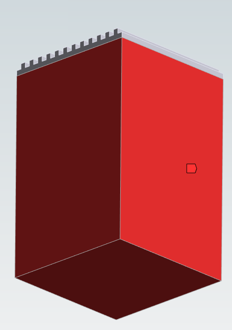
The following assumptions were applied: (i) all materials properties were considered constant; (ii) the impact of the HTF buoyancy was included by employing the Boussinesq model; (iii) heat transfer is in three dimensions; (iv) radiation heat transfer is negligible; (v) ideal thermal contact between all bodies, i.e. negligible thermal contact resistances; (vi) constant LIB cell heat generation rate during steady state (worst case scenario); (vii) due to the geometrical and thermal symmetry conditions, a quarter of the real control volume was simulated identifying three types of boundary conditions (i.e. walls), being symmetry, convection and insulation (sides, bottom) as shown in Figure 2; (viii) convective cooling on the heat sink based on an equivalent heat transfer coefficient of 20 W/m2K and 25°C, unless specified differently; (xi) insulation walls characterised by an equivalent heat transfer coefficient of 1 W/m2K and 25°C, unless specified differently.

2. 3. Mesh sensitivity analysis
A mesh based on shared topology between bodies was generated in Ansys Fluent Meshing. A thorough mesh independency study was carried out by changing the element size in all bodies and carry on simulations for three selected HTFs (air, deionised water, Cargill DE-11772). This was done to identify the minimum number of elements necessary to minimise solution sensitivity, processing time, and RAM.
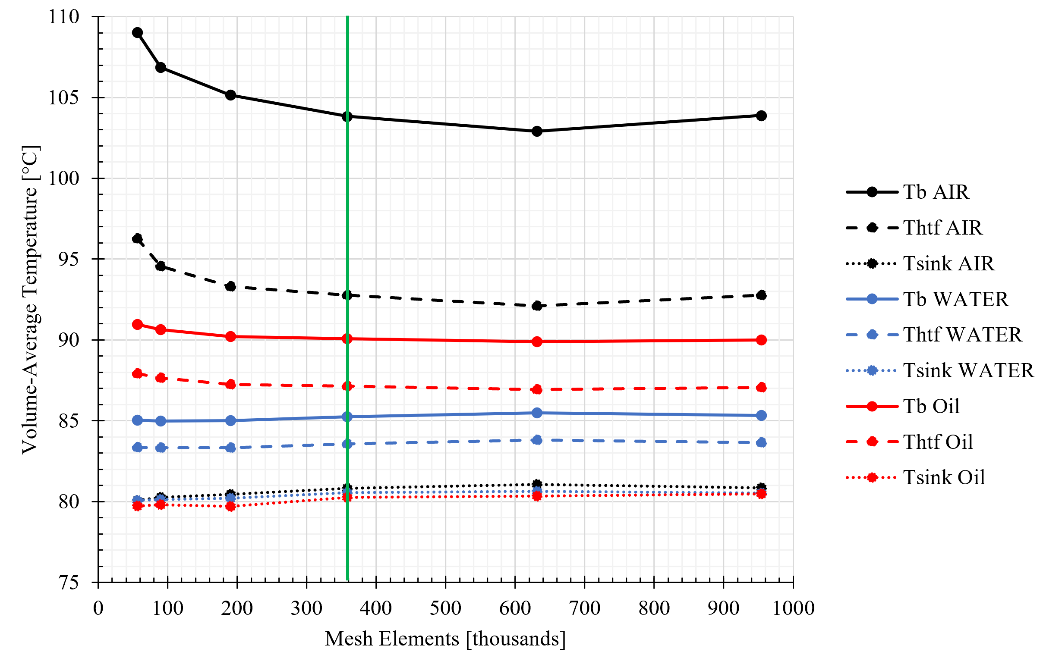
The results of the mesh independency study are reported in Figure 3, showing the variation of the volume-average temperature of battery (Tb), HTF (THTF), and heat sink (Tsink) for different mesh element counts, from course (53k elements) to fine (954k elements). It is evident that for all HTF 358k elements (green line in Figure 3) guarantee mesh independency while minimising processing time and RAM. Henceforth, this mesh was selected for all simulations.
3. Results
The benchmark TMS cooling effectiveness (including one fin, 9 heat pipes, and a topping heat sink, refer to Figure 1) is compared with the simplest TMS design where the batteries are placed within the same enclosure (same volume, excluding the topping heat sink) and exposed to air (A) or pristine dielectric oil (O). The results are reported in Table 3. The results demonstrate how the benchmark TMS evidently outperforms the simple A and O TMS in terms of Tmax minimisation while increasing the TMS mass.
Table 3: Benchmark TMS effectiveness compared to simple air (A) and oil (O) TMS, focussing on battery maximum temperature (Tmax ), temperature disuniformity ( ∆T), and TMS mass vs battery mass (mTMS )
|
Design |
Tmax(°C) |
∆T(°C) |
mTMS(%) |
|
Benchmark |
93.20 |
5.70 |
97.8 |
|
O |
149.86 |
3.32 |
79.40 |
|
A |
451.57 |
62.26 |
0.02 |
3. 1. Effect of HTF buoyancy and chemistry
To fully understand the effect of buoyancy, which is naturally present in the physics of the benchmark TMS heats transfer mechanism, the CFD model was tested with and without Boussinesq model. The results are shown in Figure 4, focussing on the volume-average temperature of the battery cells (Tb). In the absence of buoyancy, temperatures rises in all HTFs owing to restricted natural convective heat transfer. In this model, the HTF is treated effectively as a solid with equivalent thermo-physical properties. For instance, buoyancy contributes to reducing Tb from 100.16°C to 91.73°C when using Cargill DE-11772. This behaviour is reflected for all HTFs, with an average decrease of Tb across different HTFs of 5.32°C. These comparisons demonstrate that buoyancy must be included in the CFD model and improves overall cooling efficiency by enhancing heat transfer by natural convection, especially in fluids with elevated viscosities, such as dielectric oils.
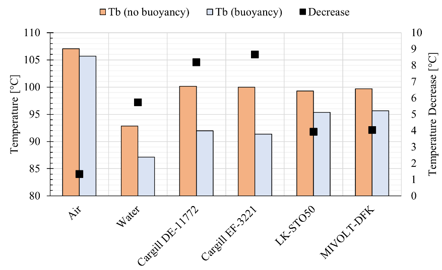
Moreover, when considering the effect of buoyancy, the best performing HTF are deionised water (impractical to be used in real battery packs due to ionisation issues) and the two commercial Cargill dielectric oils. This is because these HTF possess high specific heat capacity (cp) and limited dynamic viscosity (μ)., i.e. high Rayleigh number (Equation 5) and related predisposition to buoyancy-driven natural convection.

3. 2. Effect of LIB volumetric heat generation rate
The effect of different LIB volumetric heat generation rates on the cooling performance of the TMS were investigated using Cargill DE-11772 as the selected HTF. As expected, the volume average battery temperature Tb increases mostly linearly with the heat generation rate. At low heat generation rates (1–25 kW/m³), the TMS ensures efficient cooling, with battery temperatures in the range of 27°C to 43°C, therefore limiting the need for convection on the topping heat sink (refer to Figure 2). As the heat generation rates rises to high levels (75–100 kW/m³), Tb rises to 91.73°C, pointing to the TMS cooling limitations, necessitating supplementary cooling techniques applied to both heat sink and lateral walls (refer to Figure 2.b 2.c) to sustain safe LIB operating conditions.
3. 3. Effect of equivalent convective heat transfer coefficient on heat sink and insulation
Figure 5 illustrates the impact of varying the equivalent convective heat transfer coefficient (h) of either the topping heat sink (hconv) or insulation wall (hins) when using Cargill DE-11772 as HTF and under the volumetric heat generation rate of 100 kW/m3. It is evident that in this steady-state worst case scenario, the TMS should be exposed to 50 W/m²K at the topping heat sink (i.e. forced convection) or 15 W/m²K at the insulation wall (i.e. natural convection) to guarantee operating temperatures below 60°C. Overall, both enhanced heat sink and insulation boundary conditions are crucial for optimising thermal management and maintaining safe operating temperatures for the battery system.
3. 4. Effect of heat pipes diameter
The effect of different heat pipes diameter (refer to Figure 6) on the cooling performance of the TMS has been investigated using Cargill DE-11772 as the selected HTF. Heat pipes of 4mm (benchmark), 6mm, 8mm diameter were simulated.
The results reported in Table 4 show that the heat pipes diameter does not influence appreciably the TMS thermal performance as both battery maximum temperature (Tmax) and temperature disuniformity (∆T) reduce by 1.11% and 1.57 %, respectively. However, bigger heat pipes demand additional TMS mass.
Table 4: Effect of heat pipes diameter (dHP) on battery maximum temperature (Tmax), temperature disuniformity (∆T), and TMS mass vs battery mass (mTMS)
|
dHP(mm) |
(Tmax°C) |
∆T(°C) |
mTMS(%) |
|
Benchmark (4) |
93.20 |
5.70 |
97.8 |
|
6 |
92.55 |
5.56 |
99.5 |
|
8 |
92.16 |
5.61 |
102.1 |

3. 5. Effect of fins number and configuration
The effect of different fin numbers and their vertical distribution within the HTF enclosure on the cooling performance of the TMS has been investigated using Cargill DE-11772. Fins numbers were varied as 1 (benchmark), 2, 3, 5. The vertical distribution were either even or focussed on the top half of the HTF enclosure, as shown in Figure 7.
The results reported in Table 5 show that the configuration with 5 evenly distributed fins provides the minimum battery maximum temperature (Tmax) of 89.22 °C and temperature disuniformity (∆T) of 2.45 °C compared to all configurations; however, the mass of the TMS (mTMS) increases by 7.5 %.
Table 5: The influence of fins number (nfins) and distribution on battery maximum temperature (Tmax), temperature disuniformity (∆T), and TMS mass (mTMS)
| nfins |
Distribution |
Tmax(°C) |
∆T(°C) |
mTMS(%) |
|
5 |
Even |
89.22 |
2.45 |
105.0 |
|
3 |
Even |
89.77 |
2.85 |
101.8 |
|
2 |
Even |
90.16 |
3.04 |
99.8 |
|
5 |
Top |
89.45 |
3.22 |
104.1 |
|
3 |
Top |
89.95 |
3.26 |
100.9 |
|
2 |
Top |
90.31 |
3.44 |
99.3 |
|
1 |
- |
93.20 |
5.70 |
97.8 |
3. 6. Pareto plot overview of all cases
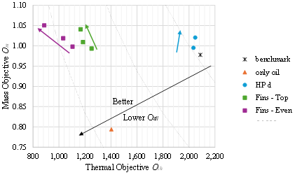
As all designs reported in Tables 3, 4, 5 are characterised by different thermal performances and additional masses, both crucial in practical EV applications as two and three-wheelers, it is quite effective to report all cases in a Pareto Plot, as shown in Figure 7. This approach has been previously proposed and employed by Landini et al. [17] and Ismail et al. [18]. The two objectives selected are Oth (thermal) and Omass (mass) for X and Y axis, respectively. These are defined as reported in Equations 6 and 7, where Tmax [K] is the battery maximum temperature, ∆T [K] temperature disuniformity, mTMS [kg] is the mass of the TMS and mcell [kg] is the mass of the LIB cells. An overall objective Oall is then calculated as the product of the two objectives Oth and Omass. By definition, the Pareto Plot shows the better performing designs located closer to the origin of the axis.


As can be clearly seen in Figure 8, the best performing design in terms of lowest Oth and Oall is the TMS characterised by 5 fins evenly distributed. All TMS with evenly distributed finds outperformance the TMS with fins located on the top. It must be also noted that the simple design with only oil has similar overall performance compared to the multiple finned designs, however it does not guarantee good Oth.

Conclusion
The study demonstrates the effectiveness of a hybrid thermal management system combining heat pipes and dielectric fluid immersion cooling for LIB packs in light electric vehicles. The hybrid system significantly outperforms conventional air cooling, reducing LIB temperatures and minimising thermal gradients, thereby preventing thermal hotspots and enhancing safety. The inclusion of buoyancy effects further improves cooling performance, especially for viscous dielectric fluids, reducing battery temperatures by up to 10°C.
At lower heat generation rates (1–50 kW/m³), the hybrid system maintains effective cooling, but as the rate increases to 100 kW/m³, the cooling capacity is challenged, with battery temperature reaching 91.13°C, indicating the need for supplementary cooling strategies under extreme conditions. Therefore, optimising the heat sink and insulation convective heat transfer coefficients is critical, as increasing these values significantly reduces LIB temperatures, highlighting the importance of sound TMS design.
Moreover, the effect of heat pipes diameter and fins number and vertical distribution is analysed, pointing to the design with 5 evenly distributed fins to be the best thermally performing while limiting additional TMS mass.
Overall, the hybrid TMS, with its combination of heat pipes, fins, and immersion cooling, offers a promising solution for efficient and compact thermal management in light electric vehicles, ensuring improved battery safety, performance, and lifespan under demanding operating conditions.
References
[1] S. Singh, S. Kumar, M. Vohra, S. Praveenkumar, D. Kumar, and S. Ghotekar, "An intense review on the performance of PCM-based lithium-ion battery cooling with aging effect in Indian climate conditions," Inorganic Chemistry Communications, vol. 169, 2024, doi: 10.1016/j.inoche.2024.113032. View Article
[2] D. M. Weragoda, G. Tian, A. Burkitbayev, K.-H. Lo, and T. Zhang, "A comprehensive review on heat pipe based battery thermal management systems," Applied Thermal Engineering, vol. 224, 2023, doi: 10.1016/j.applthermaleng.2023.120070. View Article
[3] A. Mitra, R. Kumar, D. K. Singh, and Z. Said, "Advances in the improvement of thermal-conductivity of phase change material-based lithium-ion battery thermal management systems: An updated review," Journal of Energy Storage, vol. 53, 2022, doi: 10.1016/j.est.2022.105195. View Article
[4] W. Wu, G. F. Smaisim, S. M. Sajadi, M. A. Fagiry, Z. Li, M. A. Shamseldin, and H. Ş. Aybar, "Impact of phase change material-based heatsinks on lithium-ion battery thermal management: A comprehensive review," Journal of Energy Storage, vol. 52, 2022, doi: 10.1016/j.est.2022.104874. View Article
[5] A. E. Misar and S. B. Thombre, "Thermal management of Li-ion battery pack using potting material and air cooling for electric two-wheelers," Journal of Energy Storage, vol. 101, 2024, doi: 10.1016/j.est.2024.113760. View Article
[6] S.-b. Zhang, F. Nie, J.-p. Cheng, H. Yang, and Q. Gao, "Optimizing the air flow pattern to improve the performance of the air-cooling lithium-ion battery pack," Applied Thermal Engineering, vol. 236, 2024, doi: 10.1016/j.applthermaleng.2023.121486. View Article
[7] M. Suresh Patil, J.-H. Seo, and M.-Y. Lee, "A novel dielectric fluid immersion cooling technology for Li-ion battery thermal management," Energy Conversion and Management, vol. 229, 2021, doi: 10.1016/j.enconman.2020.113715. View Article
[8] X. Wu, Y. Lu, H. Ouyang, X. Ren, J. Yang, H. Guo, X. Han, C. Zhang, and Y. Wu, "Theoretical and experimental investigations on liquid immersion cooling battery packs for electric vehicles based on analysis of battery heat generation characteristics," Energy Conversion and Management, vol. 310, 2024, doi: 10.1016/j.enconman.2024.118478. View Article
[9] J. Liu, Q. Ma, and X. Li, "Numerical study on heat dissipation performance of a lithium-ion battery module based on immersion cooling," Journal of Energy Storage, vol. 66, 2023, doi: 10.1016/j.est.2023.107511. View Article
[10] A. Thiru Kumaran and S. Hemavathi, "Optimization of Lithium-ion battery thermal performance using dielectric fluid immersion cooling technique," Process Safety and Environmental Protection, vol. 189, pp. 768-781, 2024, doi: 10.1016/j.psep.2024.06.117. View Article
[11] N. P. Williams, D. Trimble, and S. M. O'Shaughnessy, "An experimental investigation of liquid immersion cooling of a four cell lithium-ion battery module," Journal of Energy Storage, vol. 86, 2024, doi: 10.1016/j.est.2024.111289. View Article
[12] Z. Zou, J. Xie, Y. Luo, G. Zhang, and X. Yang, "Numerical study on a novel thermal management system coupling immersion cooling with cooling tubes for power battery modules," Journal of Energy Storage, vol. 83, 2024, doi: 10.1016/j.est.2024.110634. View Article
[13] Z. Wang, R. Zhao, S. Wang, and D. Huang, "Heat transfer characteristics and influencing factors of immersion coupled direct cooling for battery thermal management," Journal of Energy Storage, vol. 62, 2023, doi: 10.1016/j.est.2023.106821. View Article
[14] Y. Wang, C. Li, X. Wen, W. Cai, Y. Jiang, C. Wen, Y. Wang, L. Hu, H. Yu, H. Zhu, H. Guo, and D. Liu, "Experimental studies on two-phase immersion liquid cooling for Li-ion battery thermal management," Journal of Energy Storage, vol. 72, 2023, doi: 10.1016/j.est.2023.108748. View Article
[15] Q. Liu, C. Sun, J. Zhang, Q. Shi, K. Li, B. Yu, C. Xu, and X. Ju, "The electro-thermal equalization behaviors of battery modules with immersion cooling," Applied Energy, vol. 351, 2023, doi: 10.1016/j.apenergy.2023.121826. View Article
[16] H. Zhu, Y. Ma, J. E, and S. Wei, "Channel structure design and optimization for immersion cooling system of lithium-ion batteries," Journal of Energy Storage, vol. 77, 2024, doi: 10.1016/j.est.2023.109930. View Article
[17] S. Landini, W. Delgado-Diaz, R. Ravotti, R. Waser, A. Stamatiou, J. Worlitschek, and T.S. O'Donovan, “Effect of geometry and thermal mass of Direct-Metal-Laser-Sintered aluminium Heat Exchangers filled with phase change materials on Lithium-Ion cells’ passive cooling”, Applied Thermal Engineering, vol. 195, 2021, doi: 10.1016/j.applthermaleng.2021.117151. View Article
[18] M. Ismail, J.R. Panter, and S. Landini, "Numerical investigation of fin geometries on the effectiveness of passive, phase-change material −based thermal management systems for lithium-ion batteries", Applied Thermal Engineering, vol. 262, 2025, doi: 10.1016/j.applthermaleng.2024.125216. View Article