Journal of Fluid Flow, Heat and Mass Transfer (JFFHMT)
ISSN: 2368-6111

Volume 12 - Year 2025 - Pages 226-241
DOI: 10.11159/jffhmt.2025.023
Investigation of Heat Transfer and Vortex Dynamics in Relation to Film Cooling Effectiveness of Cratered Injection
Abhishek Verma1, Debi Prasad Mishraa1,2
1Department of Aerospace Engineering, Indian Institute of Technology, Kanpur, India 208016
abhishv@iitk.ac.in
2Department of Mechanical Engineering, National Institute of Technical Teachers' Training and Research, Kolkata, India
mishra@iitk.ac.in
Abstract - A thorough numerical analysis of of cratered injection holes which are frequently seen in turbine blades with thermal barrier coatings (TBCs)—is presented in the current research. During the TBC application process, injection holes are typically masked, resulting in a characteristic cratered geometry where the hole is surrounded by a raised layer of coating. This alteration in surface topology is expected to influence the flow behavior and cooling effectiveness compared to standard cylindrical holes. The objective of this research is to evaluate the influence of such cratered geometries on film cooling effectiveness and associated vortex dynamics. Three-dimensional simulations are performed using the k-ε to resolve the flow field and thermal characteristics. The study is conducted at a fixed mainstream Reynolds number, based on the freestream velocity and hole diameter. Film cooling effectiveness is evaluated for both cylindrical and off-centered forward cratered (OCFC) holes across three blowing ratios (BR): 0.6, 1.0, and 1.4. Air is used as the coolant, maintaining a density ratio of 1.14. The results indicate that cratered holes consistently yield higher area-averaged film cooling effectiveness in comparison to cylindrical holes. The enhancement is attributed to the altered vortex structures and improved lateral spreading of the coolant film induced by the crater geometry. The most significant performance gain is observed at BR = 1.0 with lower vorticity, where cratered holes exhibit up to a 48% improvement in cooling effectiveness.
Keywords: Cratered holes, Film cooling, Effectiveness, vorticity, Cylindrical shape, Gas turbine.
© Copyright 2025 Authors - This is an Open Access article published under the Creative Commons Attribution License terms Creative Commons Attribution License terms. Unrestricted use, distribution, and reproduction in any medium are permitted, provided the original work is properly cited.
Date Received: 2025-02-24
Date Revised: 2025-05-15
Date Accepted: 2025-06-02
Date Published: 2025-06-11
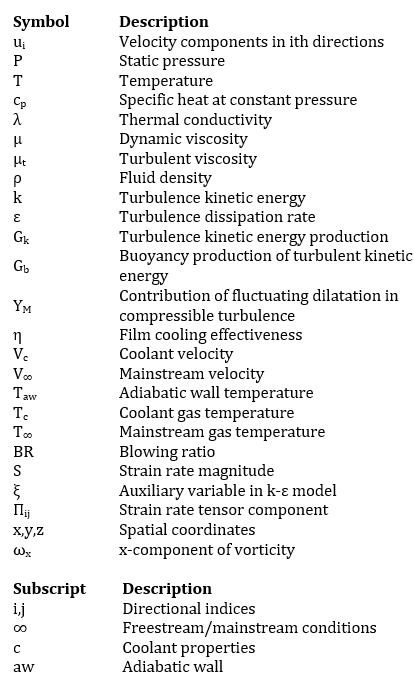
Nomenclature
1. Introduction
The gas turbine (GT) engines operate under extreme thermal conditions, particularly in the high-pressure turbine section, where blades are exposed to hot combustion gases at temperatures that often exceed the melting point of the base metal alloys [1]. To ensure the safe and efficient operation of these turbines, effective cooling strategies are essential [2,3]. Among the various cooling methods developed, film stratified cooling is mandatory for preventing turbine blades by forming a layer of air along the surface, thereby minimizing the direct impact of hot gases and reducing thermal stresses [4–6]. Traditionally, turbulated internal cooling passages [7] have been used to lower the temperature of turbine blades by enhancing convective heat transfer within the blade structure. However, to further shield the external surfaces from intense thermal loading, film cooling is employed in conjunction. In this technique, coolant typically bled from the compressor, is ejected through small discrete holes drilled in the blade’s outer surface, forming a thin insulating film that reduces heat transfer from the mainstream hot gas to the metal surface [8–10]. As turbine inlet temperatures continue to rise with advancements in engine efficiency and thrust output, the demand for more efficient and reliable cooling injection geometries has increased. In relatively low-temperature turbine environments, simple cylindrical film cooling holes, typically inclined at an angle to the surface in the direction of flow have shown adequate performance [11,12]. However, these Structures may not suffice under elevated temperature gradients or when thermal durability is a critical requirement.
To further enhance surface protection, especially in high-temperature environments such as those found in industrial gas turbines and thermal reactors, thermal barrier coatings (TBCs) have become a standard solution [13]. These are ceramic-based coatings applied in thin layers on the external surface of turbine components. During the application of TBCs, the cooling holes are often masked to prevent blockage, which inadvertently creates geometric features such as trenches or craters around the hole exit [14,15]. These features significantly alter the local flow dynamics and the interaction between both the gases. While these cratered or recessed configurations were initially considered incidental outcomes of the TBC application process, recent studies have shown that they may actually benefit film cooling performance. The cratered geometry can act as a secondary expansion zone, modifying the jet’s momentum characteristics and promoting better lateral spreading of the cold film over the flat plane [15]. This transformation in the coolant-mainstream interaction leads to a more uniform and effective cooling film. Over the years, researchers have extensively investigated various film cooling hole designs to improve cooling effectiveness, particularly under high blowing ratios (BRs), defined as the ratio of coolant jet momentum to that of the mainstream flow. The performance of film cooling holes is known to be highly sensitive to geometric factors such as hole exit shape, inclination angle, compound angle, hole aspect ratio, and spacing. Among these parameters, hole exit design has emerged as a particularly influential factor. The seminal work of Goldstein et al. [16] in 1974 was among the first to highlight the importance of hole shape in determining film cooling performance. They studied fan-shaped holes that featured lateral expansion with a 10° diffusion angle at the exit. This design reduced the jet's exit velocity and helped achieve wider coolant film coverage, significantly improving cooling effectiveness compared to cylindrical holes. Since then, numerous shaped hole designs have been developed and studied, including conical, laid-back fan-shaped, console-shaped, and anti-vortex designs[17–20]. Shaped holes have consistently shown superior performance, particularly at higher blowing ratios (BR > 0.5), where cylindrical hole layouts often fail due to excessive jet liftoff or mainstream penetration. For instance, shaped holes enable smoother coolant ejection, reduce jet separation, and maintain closer adherence of the cooling film to the surface, thus enhancing adiabatic film cooling effectiveness [21,22]. Innovative features such as triangular tabs placed upstream of the cooling holes have also been investigated [23]. These notches induce anti-kidney-pair vortices—secondary flow structures that counteract the traditional vortex pairs responsible for lifting the coolant jet off the surface. By suppressing jet penetration into the mainstream flow, these vortices promote closer adherence of the coolant film and increase the lateral spread. Experimental studies have shown up to a 300% increase in local adiabatic effectiveness using such modifications across a range of blowing ratios (0.5 < BR < 2.0). In more recent advancements, researchers have turned their attention to cratered and trenched hole geometries [14,15,24], where the hole is embedded within a shallow depression. These setups either formed deliberately or as a byproduct of the TBC masking process, offer new mechanisms for enhancing film cooling. The recessed zone acts as a buffer region where the coolant jet can expand and lose some of its momentum before entering the main flow. This transition can result in a less aggressive jet with greater lateral coverage, thereby increasing the area-averaged cooling effectiveness. The cratered configurations represent a promising alternative to conventional shaped holes, especially in applications where mechanical strength, coating durability, and simplified manufacturing are important. While fan-shaped or laid-back hole designs offer high cooling effectiveness, they may require more complex fabrication processes or suffer from durability concerns under cyclic thermal loads. Cratered holes, in contrast, can be integrated more easily during the TBC masking process and may provide comparable improvements in thermal performance. Despite the considerable progress in enhancing film cooling effectiveness through hole shaping and vortex manipulation [25], the search for optimal designs continues. The existing literature confirms that laterally diffused and shaped holes have significantly outperformed simple cylindrical geometries [8,26,27], but there is still room to explore alternative or hybrid exit arrangements. Specifically, setups like off-centered forward cratered holes, where the crater is asymmetric or offset in the streamwise direction, may hold the potential for even better cooling performance by influencing local flow separation and vortex dynamics in favorable ways. The surface characteristics that naturally develop during the masking process in thermal barrier coating (TBC) applications are quite similar to the cratered configuration that is being investigated here. Because of this, it doesn't need any extra machining or intricate shaping, which makes it a useful and affordable way to improve the performance of film cooling. Cratered holes are easily incorporated without sacrificing structural integrity or maintenance protocols, in contrast to fan-shaped or trenched holes, which may need complex manufacturing processes or provide durability issues under cyclic heat loads. Additionally, the present study's limitations are now clearly stated. Both the settling chamber's affect and the numerical model's assumption of constant thermophysical parameters can have an impact on the development of coolant flow. In order to increase forecast accuracy and fully capture the complexity of turbine cooling settings, future work will strive to integrate more realistic boundary conditions and property fluctuations, even if these simplifications are typical in preliminary parametric research.
This study aims to contribute to this ongoing exploration by focusing on the film cooling effectiveness, vortex dynamics, and flow behavior associated with cratered injection geometries. Using the k-ε turbulence model for simulations, the study compares the cooling performance of standard cylindrical holes (CY) with that of off-centered forward cratered holes across a range of blowing ratios. The results provide new insights into how crater-induced flow modifications influence cooling film attachment, lateral spreading, and overall thermal protection of turbine blade surfaces. While previous research [14,15] has demonstrated improvements in film cooling effectiveness with cratered and trenched hole geometries, the impact of cratered geometry on vortex interactions remains insufficiently explored. Additionally, the effects of varying BRs and injection exit geometries on film cooling procedures need further investigation. This study aims to address these gaps by examining the impact of cratered cooling ejection geometries on heat transfer and effectiveness. Specifically, we also investigate the role of vorticity in enhancing film effectiveness and transmission of heat through fluids. The vorticity due to jet in cross flow, which forms the rotating vortices near the injection point, depends on the BR and the associated velocity gradient that significantly affects film effectiveness. The vorticity established by the jet in cross flow also depends on injection exit shapes, which control the near injection flow velocity gradient, mostly in the vertical direction (y-direction in this research) of the resultant flow. This specific aspect has not been investigated before. The variation of the velocity gradient is also analyzed for both injection hole types. A 3D RANS approach is employed for BRs of 0.6, 1.0, and 1.4. The injection geometry and associated vorticity from the jet in cross-flow are optimized to enhance heat transfer. This numerical research uses a three-dimensional domain to compare the geometric impact of cylindrical holes and off-centered forward cratered (OCFC) holes, examining how vortex interactions and BRs effects the film layer across a flat surface.
2.Computational domain setup and specifications
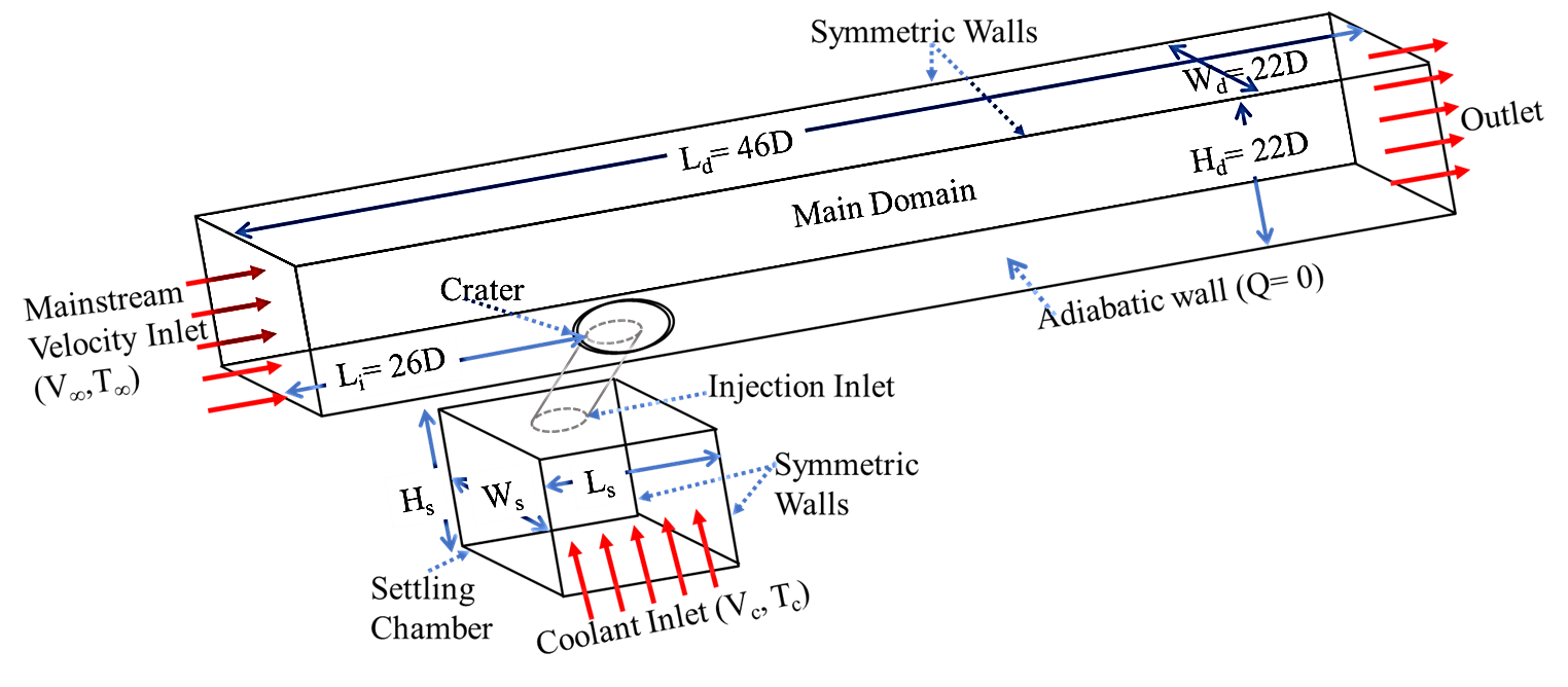
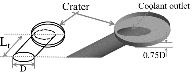
To examine the three-dimensional geometric influences, vortex structures, temperature distribution, and fluid flow behavior relevant to air-film cooling, this study investigates two configurations: a conventional cylindrical film cooling hole and a cratered setup connected to a cylindrical metering tube. The cratered design features a depression with a depth of 0.75 mm integrated into the circular tube, intended to alter jet behavior and enhance lateral coolant coverage. The computational domain (as shown in figure. 1 and 2) is segmented into three key zones: the mainstream flow duct, the injection tubes, and a settling chamber. The total domain spans (Ld) 46D in the streamwise direction and 22D in height (Hd), where D is the hole diameter. The film cooling hole is located at a streamwise distance (Li) of 26D from the inlet. The injection angle (α) is maintained at 35°, a value supported by prior optimization studies [14,15].
While the length of the coolant passage and settling chamber can influence jet development and numerical predictions, the effect of the settling chamber is excluded from the present study. The geometric arrangements and parameters used in the simulations are summarized in Table 1. The metering tube length (Lt) is set to 3.1D (see figure. 2). The entry diameter of both holes is 6.35 mm. The settling chamber dimensions are consistently kept at 14D in length, height, and width (Hs=Ws=Ls). The inclusion of a crater geometry at the exit modifies the coolant jet dynamics, reducing its momentum and promoting wider lateral dispersion, which enhances surface cooling effectiveness compared to standard cylindrical injection.
Table 1: Geometric parameters and symbols
|
Parameter |
Symbol |
Value |
|
Hole diameter |
D |
6.35mm |
|
Crater depth |
td |
0.75mm |
|
Injection angle |
Α |
35° |
|
Computational domain length |
Ld |
46D |
|
Computational domain height |
Hd |
22D |
|
Distance from inlet to hole |
Li |
26D |
|
Metering tube length |
Lt |
0.75D |
|
Settling chamber length, height and width |
Hs=Ws=Ls |
14D |
3. Grid construction
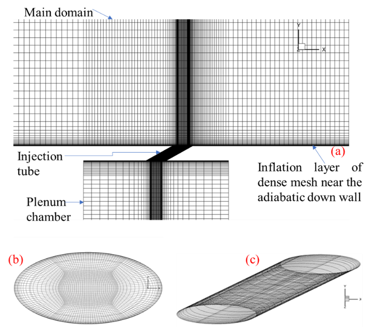
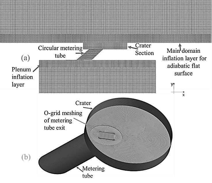
To perform the simulations, a hexahedral structured mesh was developed using a grid generation tool. Each case, cylindrical injection, and cratered injection, comprised approximately 7.9 million cells, as illustrated in Figures 3 and 4. The multi-block strategy ensured enhanced control over grid quality, especially in regions with high velocity and temperature gradients. Figures 3(a) and 4(a) depict the computational domains for the cylindrical and cratered geometries, respectively. In both cases, mesh refinement was implemented in critical regions such as the flat adiabatic surface and near the coolant injection inlets using inflation layers. Accurately resolving boundary layer formation and preserving the mixing between the coolant and mainstream flows required these layers. Each setup utilized a single injection hole with an inlet diameter D =6.35mm, and the injection tube length was maintained at 3D, adhering to standard design practices [19,28].
To ensure the fidelity of numerical results, the mesh quality was assessed using several key metrics. The non-dimensional wall distance ![]() was maintained between 30 and 300, suitable for simulations using the realizable wall function in the k-ε turbulence model. Grid skewness was kept below 0.25 to minimize numerical errors. The grid expansion ratio
was maintained between 30 and 300, suitable for simulations using the realizable wall function in the k-ε turbulence model. Grid skewness was kept below 0.25 to minimize numerical errors. The grid expansion ratio ![]() was limited to 1.2 to ensure gradual layer growth.
was limited to 1.2 to ensure gradual layer growth.
Figures 3(b)–(c) and 4(b) display the refined mesh distribution concentrated around the hole exits, where accurate resolution is critical. An O-grid meshing approach is applied to the metering section to effectively manage cell skewness, a key factor in achieving reliable numerical results. The use of the O-grid significantly enhances the local grid alignment, minimizing skewness and improving cell orthogonality. This, in turn, allows for a more accurate capture of velocity gradients, shear layers, and vortex dynamics in the vicinity of the injection holes. The refined mesh structure is crucial for resolving the intricate interactions between the coolant jet and the mainstream flow, which directly influence film cooling effectiveness. By concentrating mesh density in the near-hole region, the simulation is better equipped to represent the detailed behavior of jet penetration, spreading, and associated vortex structures.
4. Numerical procedure and turbulence model
The present study employs the commercial CFD software ANSYS Fluent to perform numerical simulations. A mathematical model was developed by solving the three-dimensional, steady-state, incompressible Reynolds-Averaged Navier–Stokes (RANS) equations, along with the energy equation [29], to accurately represent the velocity field and temperature distribution. To model turbulence, the realizable k-ε turbulence model was adopted due to its proven capability in predicting complex flow phenomena such as boundary layer development, recirculation zones, and shear-driven mixing, especially in regions subjected to strong thermal gradients. The k-ε model, particularly its realizable variant, is well-suited for film cooling applications in gas turbine engines, where it helps capture key flow features such as jet-mainstream interaction, turbulence-induced mixing, and momentum diffusion. Its formulation, which solves transport equations for turbulent kinetic energy (k) and its dissipation rate (ε), enhances the model's ability to simulate the influence of turbulence on convective heat transfer. A major advantage of the k-ε model in cooling film simulations is its robustness and computational efficiency, allowing reliable predictions of adiabatic film cooling effectiveness, jet spread, and coolant trajectory under varying operating conditions. Previous research [30,31] has validated its accuracy for a wide range of blowing ratios and mainstream turbulence intensities, confirming its suitability for evaluating coolant coverage and thermal shielding performance in high-temperature environments.
4.1 Mathematical framework
To perform the fluid flow analysis, the governing equations for incompressible mass conservation, momentum, and energy transport were solved. In the context of turbulent flow, additional equations are introduced to capture the effects of turbulence, necessitating the application of a suitable turbulence model to account for energy dissipation and turbulent transport. In this study, the fluid properties were assumed to be constant, a common and empirically supported simplification for simulations involving moderate temperature variations. The numerical solution was obtained using ANSYS Fluent, with convergence criteria set to ensure solution accuracy and stability. Specifically, the residuals for the continuity equation were restricted below 10⁻⁶, while velocity and energy equation residuals converged consistently to values less than 10⁻⁸ and 10⁻⁴, respectively. For turbulence quantities k and ε, convergence was achieved with residuals also below 10⁻⁴.To enhance accuracy, a second-order upwind discretization scheme was adopted for the momentum, energy, and turbulence variables. This approach improves solution precision, especially in regions with steep gradients, by reducing numerical diffusion and providing better spatial resolution of the flow field. This discretization method, with strict residual criteria, ensures a reliable prediction of film cooling effectiveness and thermal behavior.
Continuity and momentum equations.

Energy equations.
Realizable k-ε model. The underlying transport equations provide the turbulence kinetic energy (k), and its rate of dissipation (ε):

where
and
In the above equations, Gk denotes the turbulence kinetic energy production by the mean velocity gradients. C1ε and C2 are constants. The turbulent Prandtl numbers are denoted by σk and σε.
Adiabatic film effectiveness (η) is normalized by the temperature difference between the mainstream gas (T∞) and the coolant gas (Tc). The local effectiveness over the surface is computed using Eq. (8), which quantifies the efficiency of the coolant film in protecting the surface. This is achieved by comparing the local wall temperature to the temperatures of the mainstream and coolant gases. This normalization allows for a standardized comparison of film cooling performance under different injection geometric conditions.

4.2. Boundary conditions
Figure 1 presents the computational domain layout along with the assigned boundary conditions, which include a velocity inlet, a pressure outlet, symmetric boundaries, domain walls, and an adiabatic bottom surface. Each boundary is defined with specific conditions to accurately simulate the physical behavior of the film cooling process. At the mainstream inlet, a hot flue gas velocity of 20.2 m/s is prescribed, consistent with benchmark studies by Zhao et al. [19,28], ensuring comparability and model validation. At the point of settling (plenum) chamber's entrance, the blowing ratio (BR), an important measure demonstrating the proportion of cooling fluid to mainstream gas, is adjusted. This makes it possible to determine the mass flow of the injected coolant that is suitable for every modeling context. The flat plate's bottom surface is subjected to the adiabatic wall boundary condition (Q = 0), which prevents the transmission of heat from the wall and permits precise assessment of the effectiveness of surface film cooling. A temperature ratio (Tc/T∞) of 1.14 is maintained, with the mainstream temperature (T∞) set at 323K and the coolant temperature (Tc) fixed at 288 K. These thermal conditions are also aligned with validated literature values. A detailed list of boundary conditions and their respective zones is provided in Table 2.
Table 2. Boundary conditions of computational domain
|
Region |
Boundary condition |
Value |
|
Main duct hot gas inlet |
Velocity Inlet |
V∞=20.2 m/s, T∞=323K |
|
Coolant gas inlet |
Velocity Inlet |
BR=0.6 to 1.4, Tc=288K |
|
Main-domain outlet |
Pressure Outlet |
1 atm |
|
Side walls of main domain |
Symmetric |
- |
|
Side walls of the plenum |
Symmetric |
- |
|
All other walls |
No-Slip Walls |
- |
4.3. Grid independence test
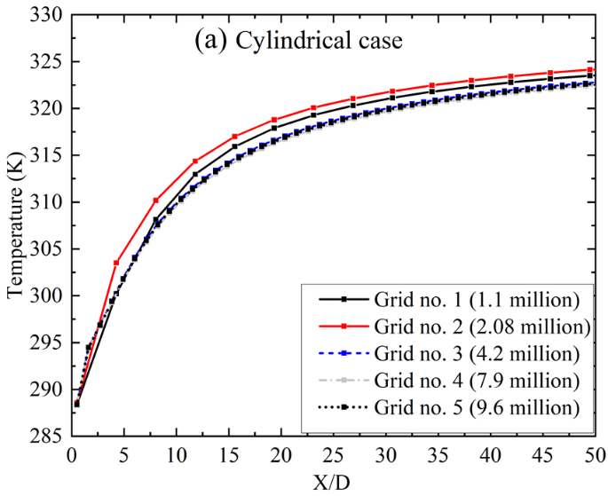
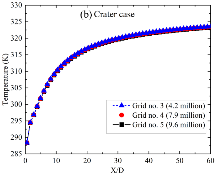
A grid independence study was conducted to identify an optimal mesh density for both cylindrical (see figure 5(a)) and cratered injection configurations (see figure 5(b)). Simulations were performed at BR=0.6, evaluating five different grid sizes ranging from 1.1 million to 9.6 million cells. A pressure-based solver was employed, using the SIMPLE algorithm to couple pressure and velocity fields. Figure 5 presents a comparison of centerline temperature profiles along the normalized streamwise distance (X/D) for each grid level. The results reveal that the profiles begin to converge beyond grid number 3 (4.2 million cells), with negligible variation observed between grid number 4 (7.9 million cells) and grid number 5 (9.6 million cells) in both injection cases. This convergence indicates that the solution is approaching grid independence, where further refinement does not significantly impact the accuracy of the results. Based on this analysis, grid number 4 was selected as the optimal mesh, offering a good compromise between computational cost and solution precision. All subsequent numerical results in the study are based on this grid resolution. The grid independence test ensures confidence in the mesh quality and establishes reliability in the predicted thermal and flow behavior across both geometries.
5. Results
5.1 Validation of present simulations
To validate the numerical model, its predictions were compared against previously reported experimental data for cylindrical injection holes, particularly from the two-phase flow study by Zhao et al. [19,28]. In their work, the coolant gas temperature was reduced due to the evaporation of water droplets, and the centerline film cooling effectiveness data were normalized accordingly. The present study adopts these conditions and evaluates the centerline film effectiveness at a mass flux ratio (BR) of 0.6, ensuring consistency with the referenced experimental setup.
Figure 6 illustrates the comparison between the simulation results and the experimental data [19,28]. The model demonstrates good overall agreement, although a slight overprediction in film effectiveness is evident across the centerline. This minor deviation can be attributed to several factors. First, inherent uncertainties in experimental measurements and the turbulence model's drawbacks, particularly the realizable k-ε model used in this study, can affect accuracy. Moreover, local flow conditions near the coolant exit, including surface roughness, geometric imperfections, and sharp hole edges, may influence vortex dynamics and mixing behavior. The larger discrepancy of 12% observed at X/D = 5 can likely be attributed to near-hole interactions, which are difficult to model accurately in RANS-based simulations. Nevertheless, the overall agreement further supports the validity of the numerical model.

5.2 Vorticity and velocity gradient variation
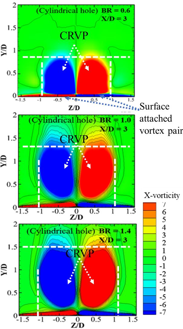
The vorticity, which is a measure of the local rotation in a fluid flow, and the velocity gradient variation are analyzed in this section. The x-component of vorticity, often referred to as ωx, represents the rotation or spinning of fluid elements around the x-axis. The x-vorticity, as plotted in figure 7 for cylindrical injection cases and in figure 8 for crater cases, is a crucial parameter in understanding the rotational dynamics of the flow. For a three-dimensional velocity field, the x-vorticity is given by the equation:
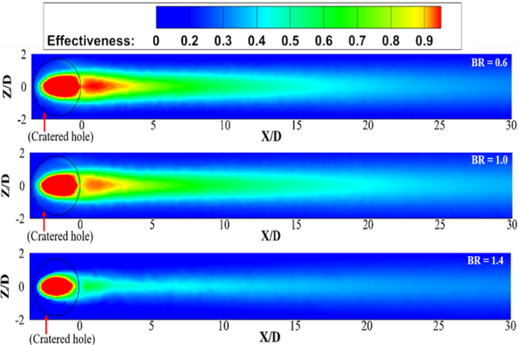
As the flow in this study is three-dimensional, x-vorticity is significant as it indicates the rotation of fluid elements about the x-axis due to variations in the transverse velocity components. The partial derivative of the y-component of the velocity with respect to z, denoted as (∂ν/∂z), measures the rate at which the y-component of the velocity changes as move in the z-direction. This term is important in film cooling to understand the lateral spread and mixing of the coolant gas at the exit of the injection and over the expanded surface as it moves in the X/D direction (see figure 9). At a BR of 0.6, the cylindrical hole exhibits strong and concentrated regions of vorticity, as illustrated in figure 7, indicating significant formation of vortices near the injection hole at a normalized distance of X/D=3. This causes the intense mixing of the coolant air with the hot mainstream, increasing the temperature of the cooling film over the flat surface. Although the BR is low, there is no separation of the film from the surface, which is beneficial. These results for the cylindrical hole are consistent with previous studies [15,32,33] that identified BR = 0.6 as the optimal BR for cylindrical cases. In contrast, the cratered hole exhibits a more diffused vorticity field with broader, less concentrated regions of vorticity as shown in figure 8. This indicates vortex formation with a comparatively lower strength than in the cylindrical case. The coolant jet remains closer to the surface, enhancing lateral spread compared to the cylindrical case and reducing jet lift-off, resulting in more uniform cooling coverage. When the BR is increased from 0.6 to 1.0, the contour of x-vorticity for both cylindrical and cratered holes at the same streamwise distance shows consistent trends. The vorticity strength is higher in the cylindrical case, indicating increased mixing of the hot mainstream with the coolant. Due to the increased momentum of the jet, separation starts near the injection point. On the other hand, at BR = 1.0, the cratered hole shows less vorticity strength compared to the cylindrical case. However, with the increase in BR, there is a minimal increase in vorticity in the cratered case. The lateral expansion is more pronounced in the cratered case at BR = 1.0, indicating better coolant spread and coverage. At a higher BR of 1.4, the vorticity continuously intensifies for both injection cases, as shown in figure 7and 8. Higher BRs are unsuitable for the cylindrical case as the jet penetration and mixing of the coolant become more pronounced [34]. The high momentum of the strongly revolving vortical structures lifts the coolant film, causing it to detach from the surface. This detachment dramatically lowers the effectiveness by preventing the coolant from maintaining close contact with the surface.
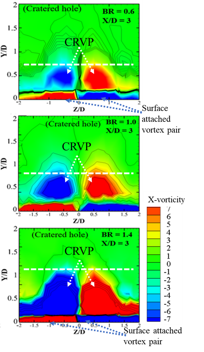
In contrast, while the vorticity also increases for the cratered hole at higher BRs (1.0 and 1.4), the coolant jet remains closer to the surface due to the injection's geometric features. There is still considerable lateral spread of the film, though slightly less than at BR = 0.6 and 1.0, and a slight jet lift-off is identified near the injection in this case too. Thus, higher BRs exacerbate the inefficiencies in cylindrical holes but do not severely impact the performance of cratered holes, which continue to provide more effective and uniform cooling coverage.
Figure 7 clearly shows that with the increase of BR, the vortex strength increases, as identified by observing the x-vorticity distribution. The white dotted lines indicate the maximum expansion of the vorticity along the yz plane. The vertical and lateral expansion of the vortex can be easily compared by observing the white lines in figure 7. It has been noticed that the vertical expansion of the vortex is more than the lateral expansion in the cylindrical case, which increases with BR. This means that coolant jets with higher momentum fly away with the mainstream hot gas at BR = 1.4, resulting in a low cooling effect on the surface. On the other hand, vertical expansion is less in the cratered injection hole case, resulting in attached coolant jet film at higher BRs.
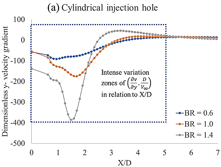
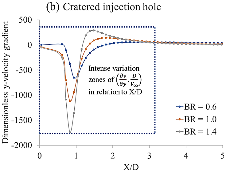
Figure 9 illustrates the dimensionless y-velocity gradient variation along the X/D direction, normalized by the mainstream velocity (V∞) and the hole diameter (D), providing a clearer picture of vortex interaction at near injection locations. The term (∂v/∂z) specifically tells us how the velocity in the y-direction varies along the z-axis, which is important for understanding vorticity in the fluid and associated lateral dispersion of film. These zones indicate significant vorticity generation and fluid element rotation around the x-axis. For BR = 0.6, the negative gradient is less pronounced, resulting in moderate mixing and spread of the coolant. At higher BRs of 1.0 and 1.4, the negative gradient becomes more intense, indicating stronger vortical structures and increased coolant-mainstream mixing. However, the higher momentum also leads to partial jet lift-off and reduced cooling effectiveness. In the cratered injection case (Figure 9(b)), the dimensionless y-velocity gradient exhibits intense variation zones up to X/D=2.7. The high negative gradient observed for BR = 0.6 enhances immediate spreading of the coolant upon ejection, leading to effective lateral distribution. At BR = 1.0 and 1.4, the gradient intensity slightly increases, but the coolant remains closer to the surface, maintaining effective lateral spread and reducing jet lift-off compared to the cylindrical case. This gradient is directly related to the calculation of x-vorticity (ωx), given by Equation (9). Figure 9 supports the observation that cratered holes, with their geometric features, produce a more controlled and diffused vorticity field, enhancing cooling performance by maintaining the coolant closer to the surface. This improved interaction between the coolant jet and the mainstream flow in the cratered hole configuration leads to better lateral spread and reduced jet lift-off, resulting in more uniform cooling coverage compared to cylindrical holes.
5.3. Geometric impact on effectiveness distribution
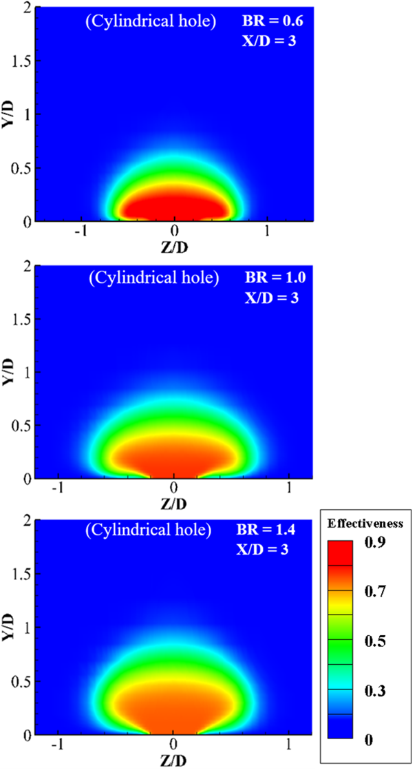
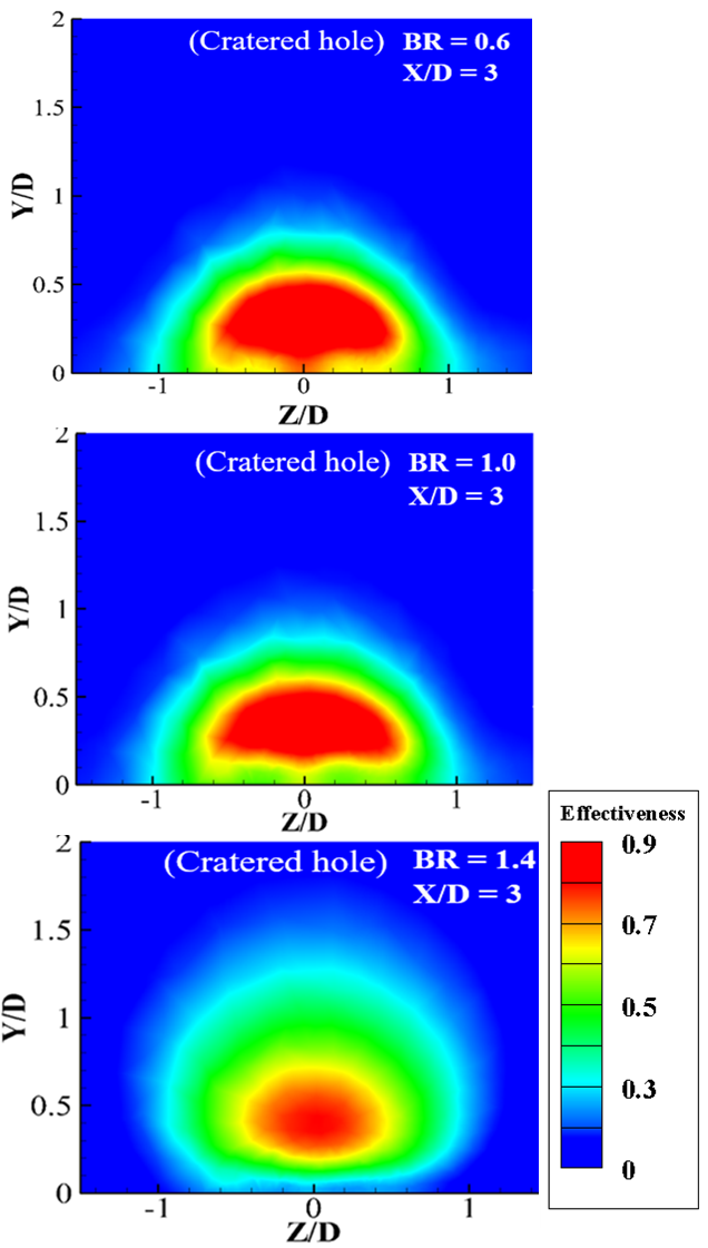
The injection geometric impacts on effectiveness with varying BRs are investigated in this section. Film effectiveness results are presented for three blowing ratios of 0.6, 1.0, and 1.4, with a density ratio of 1.14 (air), and two injection geometries: cylindrical and cratered holes. Figure 10 and 11 illustrates the local film effectiveness of CY for coolant air. Figure 12 and 13 further supports these findings by showing the lateral distribution of effectiveness for cratered injection holes at BR = 0.6, 1.0, and 1.4. The diffused vorticity field in cratered holes as discussed in previous section, enhances lateral spread and maintains the coolant film closer to the surface, resulting in more uniform cooling coverage. Figures 12 and 13 illustrates the vertical effectiveness distribution on the y-z plane for both cylindrical and cratered injection holes at different BRs (0.6, 1.0, and 1.4) and at X/D=3. At BR = 1.0, cratered holes maintain their superiority with comparatively a broader and more uniform effectiveness distribution laterally. At BR = 1.4, while the effectiveness decreases for both configurations, cratered holes still perform better except the region up to X/D = 5, providing more effective coverage than cylindrical holes specially for longer X/D distance.
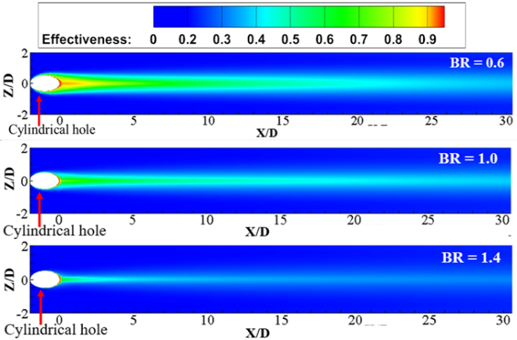
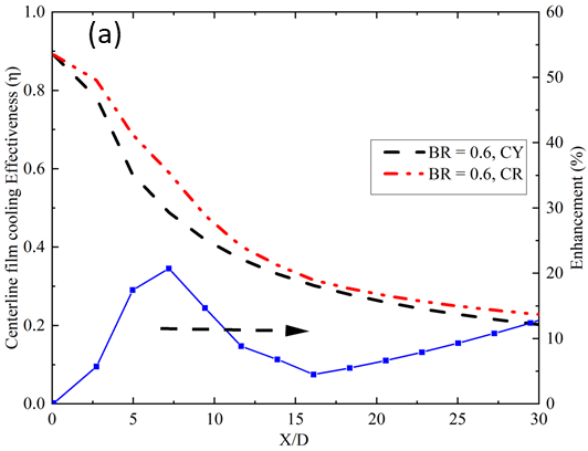
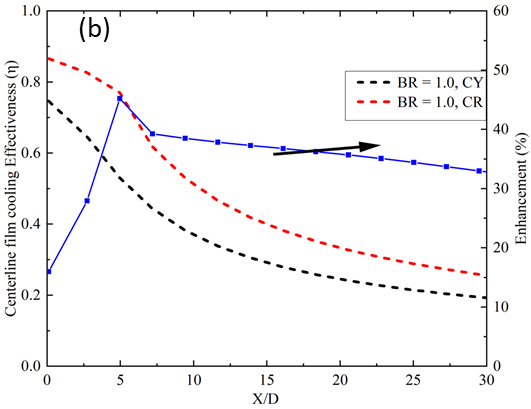
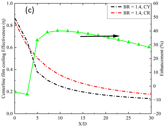
Figure 14 illustrates the centerline film cooling effectiveness and enhancement for both cylindrical and cratered holes at BR of 0.6, 1.0, and 1.4 along X/D. The data demonstrates that cratered holes consistently provide superior performance compared to cylindrical holes at all blowing ratios, except at BR = 1.4. At lower BRs (0.6), the enhancement is driven by. At BR = 0.6, the peak enhancement of 20% is found at X/D=7 compared to the cylindrical case due to the immediate and effective lateral spread of the coolant. Also, the higher film cooling effectiveness at BR = 0.6 is attributed to the expansion of the coolant jet at the crater of the injection, which causes most of the coolant fluid to remain attached for a longer X/D distance. The percentage enhancement is particularly significant at BR = 1.0, reaching approximately 48%. This enhancement is due to the controlled and diffused vorticity field produced by cratered holes, which reduces jet lift-off and ensures better cooling coverage. On the other hand, for blowing ratios of 0.6 and 1.0, the appearance of a vortices couple that results in additionally longitudinal dispersion of the film in the cratered hole case can be ascribed to enhanced effectiveness close to the injection hole (X/D<5).
The cratered hole performed better at BR = 1.0 compare to other BRs, and can be considered optimal for off-centered forward cratered (OCFC) holes. Lower effectiveness at the injection hole (X/D<10) for a high blowing ratio of 1.4 in the cylindrical example can be ascribed to the existence of a counter-rotating vortex pair (CRVP) corresponding to a jet in a crossflow. This is evident in figure 10 and 12, where the lateral distribution of effectiveness shows reduced performance at higher BRs due to increased jet penetration and lift-off. At higher BRs (1.4), although the enhancement decreases slightly, cratered holes still maintain better performance due to their ability to keep the coolant film attached to the surface and achieve more uniform lateral spread. At BR = 1.4, the film cooling effectiveness for cratered holes up to X/D = 5 is slightly lower than that of the cylindrical geometry. This decrease in effectiveness is attributed to the high-momentum coolant fluid encountering the sharp edge of the cratered hole after expanding from the circular metering tube, which directs the coolant vertically in the y direction and additionally causes separation from the film on the surface. However, the effectiveness disparity is less than 10%. With an increase in X/D distance, the effectiveness enhancement begins, and a peak enhancement of 40% is noticed at X/D=9. The reason for the lower effectiveness of the cratered hole compared to the cylindrical hole at BR = 1.4 up to X/D=5 is that the momentum of the coolant is almost equal in both injection holes, which tends to separate the film from the surface. Additionally, the crater edge directs the coolant vertically after the collision of the jet.
Finally, according to the study, areas of high x-vorticity in the cylindrical case result in more coolant–mainstream blending, which lowers interface effectiveness and film adhesion. The coolant is kept nearer the surface by the increasingly dispersed and vertically confined vortices created by OCFC holes, resulting in greater lateral coverage and lowers lift-off. This phenomenon is particularly noticeable at BR = 1.0, where the regulated vortex strength leads to a cooling effectiveness that is up to 0.5 times greater than that of cylindrical holes.
5.4. Overall (area-averaged) cooling performance
The area-averaged cooling effectiveness (ξ) and its percentage enhancement vary significantly with BRs for cylindrical and cratered injection holes (see figure. 15). At BR = 0.6, the enhancement provided by cratered holes is marginal, with a percentage increase of approximately 8%. This improvement is driven by the cratered hole's ability to create a diffused vorticity field, promoting immediate and effective lateral spread of the coolant. Additionally, at lower BR, the momentum of the coolant fluid is very low. Since the cratered hole expands the coolant jet before ejecting it into the mainstream, the coolant is further retarded, providing heavy cooling just near the hole locations.
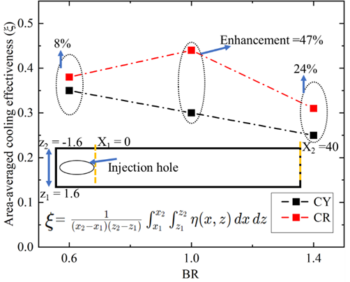
At BR = 1.0, the cratered hole exhibits the highest enhancement, approximately 48.15%. This significant increase is due to the geometric features of the cratered holes that keep the coolant closer to the surface and enhance lateral spread for longer X/D distance without significant detachment. In cylindrical holes, stronger vortices at this BR increase mixing and also cause the coolant jet to lift off, reducing effectiveness. The cratered holes, however, maintain more stable and effective cooling films by controlling vortex strength. At BR = 1.4, the enhancement percentage is approximately 24%. Although the enhancement decreases slightly due to increased jet momentum and partial lift-off, cratered holes still perform better than cylindrical ones due to their consistent lateral spread. The velocity gradient, especially in cratered holes, plays a key role in spreading the coolant efficiently across the surface, resulting in higher area-averaged cooling effectiveness.
6. Conclusion
For crucial parts like turbine blades and combustor liners in aviation combustion engines, film cooling is imperative for controlling heat transport and distributing the temperature. This numerical study explores the film cooling effectiveness of cylindrical and cratered hole geometries for three blowing ratios: 0.6, 1.0, and 1.4, using air as the coolant (with a density ratio of 1.14). The study emphasizes the significant impact of injection geometry on film cooling performance, as the distribution of effectiveness and vorticity determines the spreading of the coolant jet and its efficiency. Key conclusions include:
- Cylindrical holes demonstrate reduced effectiveness at higher BRs due to increased vorticity and early film separation.
- Cratered holes generally provide better cooling performance than cylindrical holes, except at BR = 1.4 near the injection site. The enhanced effectiveness at lower and moderate blowing ratios is attributed to a more diffused vorticity field, which promotes effective lateral coolant spread, reduces jet lift-off, and enhances coverage.
- At higher blowing ratios (BR = 1.4), the high momentum of the coolant in cratered holes leads to film separation after expansion, which diminishes near-hole effectiveness.
- Across all blowing ratios, cratered holes show superior area-averaged cooling effectiveness. At BR = 1.0, cratered holes achieve a remarkable 48.15% improvement due to the controlled vorticity and stable interaction between the coolant jet and mainstream flow. This leads to the coolant remaining closer to the surface, enhancing lateral spread.
- BR = 1.0 emerges as the optimal blowing ratio for off-centered forward crater (OCFC), offering superior cooling performance.
- cratered holes outperform cylindrical holes by maintaining better lateral and vertical spread, reducing jet lift-off, and ensuring effective coverage.
References
[1] Tian, K., Wang, J., Liu, C., Baleta, J., Yang, L., and Sunden, B., 2018, "Effect of Combined Hole Configuration on Film Cooling with and without Mist Injection," Therm. Sci., 22(5), pp. 1923-1931. View Article
[2] Jubran, B., and Brown, A., 1985, "Film Cooling From Two Rows of Holes Inclined in the Streamwise and Spanwise Directions," J. Eng. Gas Turbines Power, 107(1), p. 84. View Article
[3] Dutta, S., Kaur, I., and Singh, P., 2022, "Review of Film Cooling in Gas Turbines with an Emphasis on Additive Manufacturing-Based Design Evolutions," Energies, 15(19). View Article
[4] Gritsch, M., Schulz, A., and Wittig, S., 1998, "Adiabatic Wall Effectiveness Measurements of Film-Cooling Holes With Expanded Exits," J. Turbomach., 120(3), pp. 549-556. View Article
[5] Schmidt, D. L., Sen, B., and Bogard, D. G., 2010, "Film Cooling With Compound Angle Holes: Adiabatic Effectiveness," J. Turbomach., 118(4), p. 807. View Article
[6] Srinath Ekkad, J.-C. H., 2015, "A Review of Hole Geometry and Coolant Density Effect on Film Cooling," Front. Heat Mass Transf., 6(1), pp. 1-14. View Article
[7] Wright, L., and Gohardani, A., 2009, "Effect of Coolant Ejection in Rectangular and Trapezoidal Trailing-Edge Cooling Passages," J. Thermophys. Heat Transf., 23(2), pp. 316-326. View Article
[8] Miao, J. M., and Wu, C. Y., 2006, "Numerical Approach to Hole Shape Effect on Film Cooling Effectiveness over Flat Plate Including Internal Impingement Cooling Chamber," Int. J. Heat Mass Transf., 49(5-6), pp. 919-938. View Article
[9] Eriksen, V. L., and Goldstein, R. J., 2010, "Heat Transfer and Film Cooling Following Injection Through Inclined Circular Tubes," J. Heat Transfer, 96(2), p. 239. View Article
[10] Chen, A. F., Shiau, C. C., and Han, J. C., 2018, "Turbine Blade Platform Film Cooling with Fan-Shaped Holes under Simulated Swirl Purge Flow and Slashface Leakage Conditions," J. Turbomach., 140(1), pp. 1-11. View Article
[11] Ligrani, P. M., Wigle, J. M., and Jackson, S. W., 2008, "Film-Cooling From Holes With Compound Angle Orientations: Part 2-Results Downstream of a Single Row of Holes With 6d Spanwise Spacing," J. Heat Transfer, 116(2), p. 353. View Article
[12] Ekkad, S. V, Zapata, D., and Han, J. C., 1997, "Film Effectiveness Over a Flat Surface With Air and CO2 Injection Through Compound Angle Holes Using a Transient Liquid Crystal Image Method," J. Turbomach., 119(3), pp. 587-593. View Article
[13] Downs, J. P., and Landis, K. K., 2010, "Turbine Cooling Systems Design: Past, Present and Future," pp. 819-828. View Article
[14] Lu, Y., Dhungel, A., Ekkad, S. V., and Bunker, R. S., 2008, "Film Cooling Measurements for Cratered Cylindrical Inclined Holes," J. Turbomach., 131(1), p. 011005. View Article
[15] Kalghatgi, P., and Acharya, S., 2015, "Improved Film Cooling Effectiveness With a Round Film Cooling Hole Embedded in a Contoured Crater," J. Turbomach., 137(10), p. 101006. View Article
[16] Goldstein, R. J., Eckert, E. R. G., and Burggraf, F., 1974, "Effects of Hole Geometry and Density on Three-Dimensional Film Cooling," Int. J. Heat Mass Transf., 17(5), pp. 595-607. View Article
[17] Cho, H. H., Rhee, D. H., and Kim, B. G., 2001, "Enhancement of Film Cooling Performance Using a Shaped Film Cooling Hole with Compound Angle Injection," JSME Int. Journal, Ser. B Fluids Therm. Eng., 44(1), pp. 99-110. View Article
[18] Gao, Z., Narzary, D. P., and Han, J. C., 2008, "Film Cooling on a Gas Turbine Blade Pressure Side or Suction Side with Axial Shaped Holes," Int. J. Heat Mass Transf. View Article
[19] Zhao, L., and Wang, T., 2014, "An Experimental Study of Mist/ Air Film Cooling on a Flat Plate with Application to Gas Turbine Airfoils-Part I: Heat Transfer," J. Turbomach., 136(7), pp. 1-9. View Article
[20] Liu, C., Zhu, H., Bai, J., and Xu, D., 2010, "Film Cooling Performance of Converging-Slot Holes With Different Exit-Entry Area Ratios," J. Turbomach., 133(1), p. 011020. View Article
[21] Wang, C., Zhang, J., Feng, H., and Huang, Y., 2018, "Large Eddy Simulation of Film Cooling Flow from a Fanshaped Hole," Appl. Therm. Eng., 129, pp. 855-870. View Article
[22] Tyagi, M., and Acharya, S., 2003, "Large Eddy Simulation of Film Cooling Flow from an Inclined Cylindrical Jet," J. Turbomach., 125(4), pp. 734-742. View Article
[23] Kamat, H., Shenoy, S. B., and Kini, C. R., 2017, "Effect of V-Shaped Ribs on Internal Cooling of Gas Turbine Blades," J. Eng. Technol. Sci. View Article
[24] Zhang, R., Song, Y., Han, S., Zhou, L., Li, L., Zhang, H., and Du, X., 2022, "Film Cooling Performance Enhancement of Serrate-Type Trenched Cooling Holes by Injecting Mist into the Cooling Air," Int. J. Therm. Sci., 179(April), pp. 1-16. View Article
[25] Hodges, Craig P. Fernandes, E. F., 2019, "Flow Statistics and Visualization of Multirow Film Cooling Boundary Layers Emanating from Cylindrical and Diffuser Shaped Holes," J. Turbomach., 141(6). View Article
[26] Schroeder, R. P., and Thole, K. A., 2017, "Effect of In-Hole Roughness on Film Cooling from a Shaped Hole," J. Turbomach., 139(3). View Article
[27] Webster, Z. D., Bogard, D. G., Fox, D. W., McClintic, J. W., Jones, F. B., and Dyson, T. E., 2018, "Flow Physics of Diffused-Exit Film Cooling Holes Fed by Internal Crossflow," J. Turbomach., 141(3), p. 031010. View Article
[28] Zhao, L., and Wang, T., 2014, "An Experimental Study of Mist/Air Film Cooling on a Flat Plate with Application to Gas Turbine Airfoils-Part II: Two-Phase Flow Measurements and Droplet Dynamics," J. Turbomach., 136(7), pp. 1-9. View Article
[29] Kanani, H., Shams, M., and Ebrahimi, R., 2009, "Numerical Modelling of Film Cooling with and without Mist Injection," Heat Mass Transf. und Stoffuebertragung, 45(6), pp. 727-741. View Article
[30] Cerantola, D. J., and Birk, A. M., 2017, "Quantifying Blowing Ratio for Shaped Cooling Holes," J. Turbomach., 140(2), p. 021008. View Article
[31] Sun, X., Zhao, G., Jiang, P., Peng, W., and Wang, J., 2018, "Influence of Hole Geometry on Film Cooling Effectiveness for a Constant Exit Flow Area," Appl. Therm. Eng. View Article
[32] Kim, J. H., and Kim, K. Y., 2018, "Film-Cooling Performance of Converged-Inlet Hole Shapes," Int. J. Therm. Sci., 124(May 2017), pp. 196-211. View Article
[33] Brown, A., and Saluja, C. L., 1979, "Film Cooling from a Single Hole and a Row of Holes of Variable Pitch to Diameter Ratio," Int. J. Heat Mass Transf., 22(4), pp. 525-534. View Article
[34] Baldauf, S., Schulz, A., Wittig, S., Stromungsmaschinen, T., Scheurlen, M., and Kwu, S. A. G., 2016, "An Overall Correlation of Film Cooling Effectiveness From One Row of Holes," (2).