Journal of Fluid Flow, Heat and Mass Transfer (JFFHMT)
ISSN: 2368-6111

Volume 12 - Year 2025 - Pages 207-225
DOI: 10.11159/jffhmt.2025.022
Analysis of Two-Phase Film Cooling Mechanisms and Mist Concentration Effects for Enhanced Performance Using Laid-Back Fan-Shaped Holes
Abhishek Verma1, Debi Prasad Mishra1,2
1Department of Aerospace Engineering, Indian Institute of Technology, Kanpur, India 208016
abhishv@iitk.ac.in
2Department of Mechanical Engineering, National Institute of Technical Teachers' Training and Research, Kolkata, India
mishra@iitk.ac.in
Abstract - Film cooling plays a crucial role in protecting gas turbine engine components from extreme temperatures. Recent research has highlighted the potential benefits of introducing water mist into film cooling holes. This study investigates the influence of varying mist droplet concentrations while maintaining a constant droplet size of 5μm. The cooling process is analyzed using the k-ε turbulence model with enhanced wall treatment. Key parameters such as the blowing ratio, momentum flux ratio, and jet vorticity are examined to assess their impact on cooling performance. To simulate the behavior of mist droplets, we employ the discrete phase model with a stochastic tracking approach, allowing for the detailed tracking of individual droplets within the flow field. Mist concentrations of 2%, 4%, 7%, and 10% are evaluated. The results indicate that at a blowing ratio of 1, a higher mist concentration of 10% enhances cooling effectiveness. At a BR of 2, the same mist concentration promotes deeper penetration of the coolant jet into the mainstream flow. In the far downstream region, higher mist concentrations aid in the development of the coolant film along the flat surface, further improving film cooling effectiveness. Additionally, the study highlights the significance of vortex structures generated by crossflow interactions, which play a vital role in coolant–mainstream mixing and overall cooling performance.
Keywords: Effectiveness, Laid-back fan-shaped, Film cooling, Mist models.
© Copyright 2025 Authors - This is an Open Access article published under the Creative Commons Attribution License terms Creative Commons Attribution License terms. Unrestricted use, distribution, and reproduction in any medium are permitted, provided the original work is properly cited.
Date Received: 2025-02-25
Date Revised: 2025-05-15
Date Accepted: 2025-06-02
Date Published: 2025-06-09
Nomenclature
Symbols
1. Introduction
Gas turbines are well-known internal combustion engine that operates in very high temperatures. Increasing the operational lifespan of gas turbine blades can be effectively achieved through advanced cooling techniques, specifically film cooling of the blade surface [1–3]. Traditional methods have employed cylindrical cooling holes; however, recent advancements have focused on optimizing the hole geometry to enhance cooling performance [4–6]. One such advancement involves the implementation of film-cooling holes with a diffuser-shaped expansion at the exit portion of the hole [7,8]. The key mechanism behind this improvement lies in the increased cross-sectional area at the hole exit compared to a standard cylindrical hole. This geometric modification is hypothesized to significantly improve film-cooling efficiency on gas turbine blades. This expansion leads to a reduction in the mean velocity of the exiting jet and subsequently decreases the momentum [9]. As a result, the jet's penetration into the mainstream flow is diminished, which enhances the cooling efficiency by maintaining a more stable and adherent coolant film on the blade surface [10–12]. Moreover, the lateral expansion of the hole plays a crucial role in improving the lateral spread of the cooling jet. This broader dispersion ensures better coverage of the airfoil in the lateral direction, leading to a higher laterally averaged film-cooling efficiency. Empirical studies [11,13] have corroborated these theoretical benefits, demonstrating that cooling holes with expanded exits outperform traditional cylindrical holes in terms of film-cooling performance. Specifically, research has shown that laterally expanded holes result in significant improvements in adiabatic effectiveness. For example, studies [5,14,15] reported improved film-cooling performance using laterally expanded holes, whereas similar enhancements were observed for forward-expanded holes in studies [9,16]. Oliver et al. [17] investigated the effect of freestream Mach number on shaped-hole film cooling using LES at Mach 0.25 and 0.5. Results show a >40% drop in cooling effectiveness at higher Mach due to jet separation, asymmetry, and in-hole shocks. Their findings highlight the sensitivity of cooling performance to Mach number and the need for further joint experimental-computational studies. In order to enhance power production and thermal efficiency in gas turbines, mist enabled film cooling has also been thoroughly studied recently [18]. The behavior of mist films and their relationship to the mainstream flow have been examined in a number of research studies [19–21]. Ragab and Wang [22] evaluated mist/air film cooling with fan-shaped hole across long downstream distances and achieved better cooling efficiency than air-only film cooling. Numerical studies of mist jets striking circular target boundaries showed that the inclusion of droplets significantly increased the thermal transport efficiency. According to computational studies, adiabatic cooling effectiveness can be increased by 30–50% with even a little mist introduction (2% of coolant flow rate), especially in downstream areas where single-phase film cooling is less productive. Jiang et al. [23] investigated the improvement of film cooling by infusing water mist into the air by computational modeling utilizing the Eulerian-Lagrangian particle detection technique. Mist film cooling was expanded to moving turbine blades in subsequent studies, which investigated variables such as blowing ratio (BR), rotational speed, droplet size, momentum flux ratio (MR), and mist percentage (Cm). The findings demonstrated a non-linear trend with mist proportion, with mist cooling efficacy decreasing as rotating speed increases. Cooling performance was enhanced by tiny droplets and lower BRs. According to study by Kim et al. [24], cooling effectiveness rises as mist concentrations and droplet sizes decrease. Complementary research investigated mist-assisted film cooling on flat plates, determining crucial variables like droplet diameter and Cm that affect cooling efficiency. The effectiveness of film cooling both with and without mist on smooth plates was investigated in additional works [25,26] using dual-phase numerical computations. The results showed that larger mist volumes greatly increased cooling effectiveness, while tiny drops performed superior in terms of coolness. Considering extreme temperatures circumstances, research [27–29] on steam cooling systems for turbine blades demonstrated that cooling may produce an average improvement of 100% with 5% mist infusion. Under actual gas turbine circumstances, simulations of [30] shown that mist cooling produced a cooling boost of 5–10%, which led to a 30-68K decrease in adiabatic wall temperature. Investigations by Li and Wang [21,28,29] into mist cooling on curved planes, particularly near the leading edge, revealed that smaller mist droplets significantly enhance cooling. This study numerically examines the combined influence of turbulent intensity and mist concentration on film cooling effectiveness through cylindrical injection. Zhao and Wang's [31,32] experiments showed that mist/air film cooling could achieve up to 190% lateral enhancement and 128% overall enhancement at the centerline. In a comparable manner in internal blade cooling applications, Li et al. [28] reported that mist insertion into steam improved the transmission of heat by as much as 200% close to the stagnation region. Numerical simulations demonstrating a 30% enhancement on the trailing surface and a 20% improvement on the forward surface in revolving ribbed rectangular channels with 2% mist injection additionally confirmed the models created for mist/steam jet cooling, which included heat transfer to the steam, discrete mist, and colliding droplets. Zhang et al. [33] demonstrated that serrated trenched holes combined with mist injection significantly enhance turbine vane cooling. Introducing a wet-bulb-temperature-based effectiveness metric (WFCE), they showed that lower serrate angles, higher mist concentrations, and smaller droplet diameters improve WFCE. An empirical correlation supports further theoretical and practical applications. A clear understanding of the interaction between MR and Cm under fixed turbulence intensity, is essential for optimizing film cooling performance, particularly in configurations using Laid-back fan-shaped holes. However, despite these advances, a critical research gap remains: the combined effect of mist concentration and blowing ratio using Laid-Back Fan-Shaped Injection Holes (LFIH) over an extended streamwise domain has not been thoroughly examined. Most previous works have either neglected the presence of a plenum chamber or limited the analysis to small X/D ranges. Moreover, interactions between mist droplet behavior, jet momentum, and vorticity structures under these configurations are not well understood.
This study investigates the effects of Cm, BR, and MR on the performance of coolant film over a flat surface. While previous research [7-8] has mostly examined limited X/D ranges for laid-back fan-shaped holes (LFIH), significant gaps remain in understanding how cooling effectiveness varies across broader X/D zones. Moreover, most earlier studies [34] have neglected the influence of a plenum chamber attached to the flow domain, despite its substantial role in altering coolant distribution and creating recirculation regions. In this study, the inclusion of a plenum chamber reveals its critical impact on flow dynamics and the spatial dispersion of the cooling film, which has often been underestimated in past analyses. The numerical investigation focuses on the combined effects of BR and Cm on film cooling efficiency. Both area-averaged (overall) mist cooling effectiveness and lateral coolant film distribution are evaluated for the LFIH configuration. The area-averaged mist cooling effectiveness is used as a key metric to assess how effectively the surface is cooled in the presence of mist, while also accounting for geometric modifications of the injection hole. This metric reflects the efficiency with which the coolant fluid reduces surface temperature, considering both the injection hole shape and turbulence in the flow. The complex interdependent influence between MR, Cm, and BR poses a significant challenge in optimizing film cooling with LFIH. This study addresses this challenge by analyzing the interdependent effects of these parameters on coolant film behavior across the entire surface, including the distribution of vorticity at extended X/D locations. The unique contribution of this work lies in offering a comprehensive parametric analysis validated against experimental data of mist-enhanced film cooling using LFIH, revealing optimal conditions and functional correlations that can guide future turbine blade cooling designs.
2. Injection Patterns and Computational Flow Region
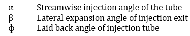
To conduct a reliable and detailed investigation of film cooling behavior, the study employs a meticulously designed computational domain that emphasizes both geometric accuracy and flow fidelity. This domain is purpose-built to resolve the complex interactions between coolant jets and the mainstream flow, particularly the influence of injection hole shape on the resulting thermal and fluid dynamic fields. As illustrated in Figure 1, the simulation is carried out within a fully three-dimensional domain that realistically replicates the physical setup under consideration. Central to this configuration is the use of Laid-Back Fan-Shaped Injection Holes (LFIHs), a geometry known for promoting enhanced lateral coolant dispersion. These injection passages are seamlessly embedded between two critical regions: an upstream plenum chamber and the main flow duct. This integrated layout ensures a continuous and representative simulation of coolant delivery from the reservoir to the hot gas path. The entire computational domain is logically divided into three primary zones: the plenum chamber, which acts as the coolant reservoir; the injection tubes, through which the coolant is delivered; and the main flow channel, where coolant–mainstream interaction and surface cooling occur. The geometric and boundary configurations of these regions are carefully depicted in Figure 1, providing a comprehensive visualization of the model structure. To facilitate generalization and simplify analysis, all dimensions are expressed in non-dimensional terms, normalized by the diameter of the injection hole. These normalized values are clearly summarized in Table 1, allowing for scalability and ease of comparison across different operating conditions or geometrical configurations.
Table 1. Computational domain parameters and their normalized values
|
Parameter |
Value |
|
Length to domain end (Ldi) |
120D |
|
Main domain height (Hm) |
24D |
|
Main domain length (Lm) |
145D |
|
Plenum width (Wp) |
14.2D |
|
Plenum height (Hp) |
14.2D |
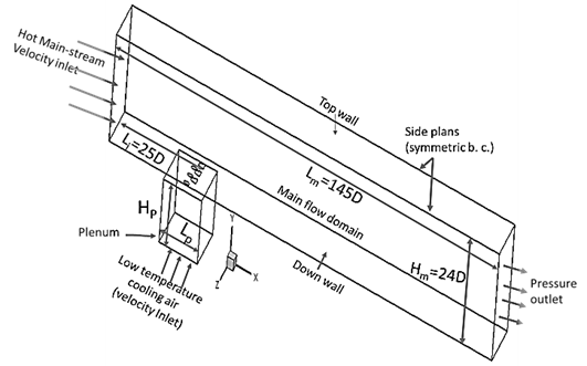
Figure 2 presents the coolant injection schematic used in the film cooling analysis, featuring a single row of three Laid-Back Fan-Shaped Injection Holes. These holes are arranged with an inter-hole pitch (P) of 3.2D, ensuring uniform spacing. The region of interest within the computational domain is carefully defined, extending laterally from Z/D = -1.4 to 1.4 and axially from X/D = 0 to 100, allowing for comprehensive analysis of flow dynamics and coolant film dispersion. Each injection hole is oriented at an inclination angle (α) of 30°, with a streamwise laid-back angle (ɸ) of 14° and a lateral expansion angle (β) of 14°. Figures 1 and 2 collectively provide a detailed view of the injection tube’s integration with the main flow domain, including the throat length (Lt) and total injection length (L). The geometric design promotes effective lateral spreading and enhances the surface coverage of the coolant film, thereby improving overall film cooling effectiveness.
1.1 Computational domain and grid construction
A structured hexahedral computational grid comprising approximately 2.5 million elements was generated using ICEM-CFD to accurately represent the flow domain associated with LFIH. The mesh design ensures topological consistency and smooth transitions across all three major regions of the computational domain: the main flow duct, the injection tubes, and the plenum chamber, as depicted in Figure 3. Special attention was given to mesh refinement near the coolant injection region, particularly around the hole exit, where high-velocity gradients, flow separation, and thermal mixing are expected to occur. These injection apertures have an inlet diameter (D) of 6.35 mm, and the injection tube extends to a length of 3D, as detailed by Ragab and Wang [22]. These apertures were oriented at an inclination angle of 30°, with laid-back and lateral expansion angles of 14° each, to promote lateral spreading of the film. The mesh around the hole exit and film region was designed with non-uniform cell sizing and inflation layers, ensuring finer resolution close to the flat adiabatic surface. These inflation layers help capture near-wall phenomena such as the viscous sublayer and thermal boundary layer, essential for resolving convective heat transfer accurately. The first layer thickness was calculated based on a target y+ value of less than 1, using the expression:

Where y is the first cell height, ν is the kinematic viscosity, and uτ is the friction velocity derived from wall shear stress. This ensured the accurate implementation of enhanced wall treatment models in ANSYS Fluent during RANS-based turbulence modeling.
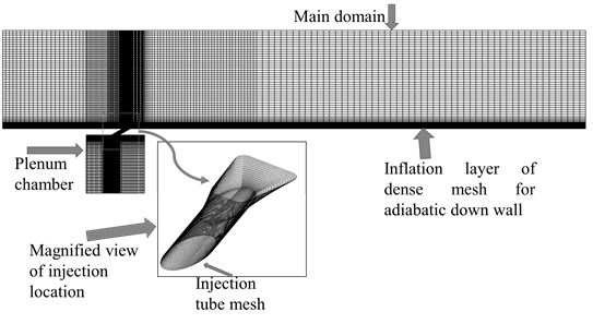
Figure 3 presents a zoomed-in view of the meshing strategy at the injection site, showing a dense node concentration near the exit of the holes and in regions of high thermal gradients. This local refinement is critical for resolving shear layers, jet penetration behavior, and vortex structures such as counter-rotating vortex pairs (CRVPs). Mesh quality metrics, such as orthogonal quality (>0.3) and aspect ratio (<10), were strictly maintained to ensure solver stability and convergence accuracy. The mesh structure is reinforced with inflation layers, increasing density near the flat adiabatic surface and the entry points of the film cooling apertures.
1.2 Computational setup for turbulence and governing equations
The governing transport equations consist of the incompressible mass conservation, momentum, and energy equations, with gas properties assumed to remain constant throughout the domain. In the Discrete Phase Model (DPM) simulations, drag forces acting on the droplets result in momentum exchange between the dispersed and continuous phases, altering the overall flow field. These interactions are incorporated into the Eulerian domain as source terms (DPM sources), enabling the solver to capture the influence of droplet dynamics on the gas phase accurately A coupling is established between the unsteady DPM and the steady-state Eulerian phase due to the continuous particle injection. The simulation follows a Eulerian-Lagrangian framework, where the fluid phase is solved using the Navier–Stokes equations, and individual droplets are tracked through a Lagrangian approach, allowing for a detailed evaluation of droplet trajectories, residence time, and interactions with the cooling surface. To resolve turbulence, the realizable k–ε model is employed. This model offers a robust prediction of turbulent transport and dissipation, particularly for complex flows involving jet-in-crossflow interactions and recirculation typical in film cooling configurations. To enhance numerical accuracy and reduce discretization error, especially in regions with steep gradients (e.g., near the wall or jet exit), a second-order upwind scheme is applied for spatial discretization to approximate the variable at the cell face:

Where ϕf is the variable value at the face, ϕP is the value at the cell center, and ![]() is the displacement vector from the cell center to the face center. This formulation ensures that the solution maintains second-order accuracy, minimizing numerical diffusion and capturing finer details of temperature, velocity, and species gradients in the film cooling region.
is the displacement vector from the cell center to the face center. This formulation ensures that the solution maintains second-order accuracy, minimizing numerical diffusion and capturing finer details of temperature, velocity, and species gradients in the film cooling region.
Continuity and momentum equations

Energy equations
Species transport equations
Turbulent kinetic energy
Turbulent dissipation rate equation
Discrete phase
The motion of each droplet within the mist flow is governed by a balance between inertial forces and the external forces acting upon it primarily aerodynamic drag from the surrounding fluid. This dynamic interaction is mathematically represented through a force balance equation, which quantifies the droplet's acceleration in response to these competing effects. The governing relation is presented below:
where FD is the drag force per unit particle mass.
The drag coefficient (CD) for smooth particles can be derived from:
Here, a1, a2, and a3 are constants that work for different ranges of Reynolds numbers as defined by Morsi and Alexander [35].
The process of droplet vaporization initiates once the droplet's temperature reaches the specified vaporization threshold, denoted Tvap . Vaporization continues progressively as thermal energy is absorbed, and persists until one of two conditions is met: either the droplet temperature rises to the boiling point, Tbp or all volatile components within the droplet those prone to rapid evaporation have been fully depleted.
To account for turbulence effects in the droplet path, stochastic tracking is used. The instantaneous velocity fluctuations acting on droplets are given by:
The eddy lifetime, i.e., the characteristic time over which a turbulent eddy influences droplet motion, is calculated by:

The local adiabatic film-cooling effectiveness is defined as the non-dimensional temperature difference that quantifies the cooling performance of a coolant film over a surface. It is expressed as:
where T∞ is the freestream (mainstream) temperature, Taw is the adiabatic wall temperature, and Tc is the coolant temperature. This definition uses the freestream temperature as the reference to quantify how effectively the coolant protects the surface from hot gas exposure.
The quantity of water droplets in the air, expressed as a percentage of the total mass flow rate of the coolant air (mair), serves as a measure of the concentration of water droplets within the coolant stream. Mist Concentration (%) is defined as:

where mist concentration (%) is the mass fraction of water droplets in percentage form. mmist is the mass flow rate of water droplets, representing the mass of water droplets in the air stream. mair is the total mass flow rate of the air, representing the total mass of air flowing in the system.
1.3 Numerical method, turbulence model validation, and grid-independent test
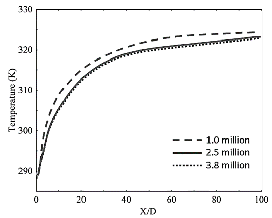
A grid sensitivity analysis was carried out to ensure mesh independence, as illustrated in Figure 4. The comparison across multiple grid densities revealed minimal variation in wall temperature and cooling effectiveness, indicating that further refinement would not significantly impact accuracy. Based on this evaluation, Grid No. 2, comprising approximately 2.5 million structured hexahedral elements, was selected for all subsequent simulations due to its optimal balance between computational efficiency and numerical accuracy. This grid also provided sufficient resolution near the wall and hole exit regions, capturing critical gradients in velocity and temperature without compromising solver stability.
The numerical simulations were conducted using a three-dimensional, steady-state, incompressible Reynolds-Averaged Navier–Stokes (RANS) framework, incorporating the energy equation to model heat transfer effects. To resolve turbulence behavior and flow separation near the wall, the realizable k–ε turbulence model with enhanced wall treatment was employed. This model is known for improved accuracy in predicting jet dispersion, boundary layer flow, and separation under strong thermal gradients, and showed excellent agreement with experimental data [36,37]. To maintain stability and accuracy in pressure–velocity coupling, the SIMPLEC algorithm was used. This method offers faster convergence by reducing the number of required iterations for pressure correction, especially useful in large three-dimensional grids like grid No. 2. By providing better pressure-velocity linkage, SIMPLEC ensures a stable and consistent solution throughout the domain, particularly in regions with strong recirculation, high-velocity gradients, and coolant–mainstream interaction near the film injection site.
1.4 Boundary conditions
Figure 1 offers a comprehensive depiction of the computational setup, showcasing the arrangement of two distinct velocity inlets, a single outlet with specified pressure, and walls modeled with adiabatic thermal conditions. This figure also emphasizes the geometric symmetry of the domain, clearly delineating the symmetry planes along with their associated boundary constraints and spatial subdivisions. At the inflow boundary of the primary flow channel, a freestream velocity of 20 m/s is prescribed for the hot gas. This velocity selection is intentionally aligned with the reference parameters used in the work of Ragab and Wang [37], thus supporting the reliability and comparability of the simulation results. An essential aspect of the boundary design is the enforcement of a blowing ratio (BR) at the lower surface of the plenum chamber, which enables accurate regulation of coolant and mist injection into the flow domain. The corresponding MR is determined by adjusting the mass flow rate of the coolant entering through the plenum, ensuring a physically representative modeling of the coolant–mainstream interaction. To maintain uniformity across all simulated scenarios, the study consistently applies a density ratio of 1.14 and a droplet diameter of 5μm for the injected mist. These values are deliberately selected to mirror conditions reported in prior validated studies [15,22,32], thereby enhancing the credibility and validation of the current computational methodology. For organizational clarity, the boundary condition settings and flow characteristics for different zones are systematically summarized in Tables 2 and 3, which serve as a consolidated reference for replicating or extending the numerical framework.
Table 2. Defined boundary conditions for computational analysis
|
Zone |
Condition |
Values |
|
Hot air inlet |
Velocity |
20 m/s, 327 K |
|
Coolant inlet |
Velocity |
BR: 1.0-2.0, 288.35 K |
|
Outlet |
Pressure |
1 atm |
|
Side Walls |
Symmetry |
- |
|
Remaining Walls |
No-Slip |
- |
Table 3. Defined boundary layer parameters for the computational domain
|
Boundary layer specifications |
Values |
|
Reynolds number based on characteristic length, ReD=V∞×D/ν |
7178 |
|
Momentum thickness, δm (X/D=−6) |
0.73 |
|
Reδm =V∞× δm/ν |
789 |
|
Boundary layer thickness, δ99 |
5.3mm |
2 RESULTS and DISCUSSION
2.1 Validation of numerical model
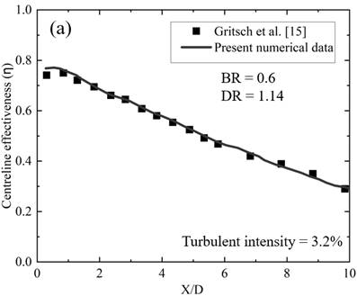
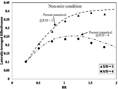
The validity of the present numerical study is assessed through a comparative analysis with experimental data from Gritsch et al. [15], which investigated LFIH using air as the coolant. This comparison is essential for evaluating the capability of the selected turbulence model to accurately capture the complex physics of the film cooling process. As illustrated in Figure 5, the numerical results show good agreement with the experimental data in terms of both centerline effectiveness and laterally averaged film cooling effectiveness.
Figure 5(a) presents a comparison of centerline effectiveness (η) along the streamwise direction up to X/D=10, showing that the predicted values closely follow the experimental trend. A minor overprediction is observed in the region from X/D=0 to X/D=2, with a maximum deviation of less than 5%, likely due to the inherent limitations of the turbulence model in resolving near-hole flow behavior and initial mixing. Figure 5(b) compares the laterally averaged effectiveness at two streamwise locations, X/D=2 and X/D=6, across a range of BR. The simulation slightly overpredicts the effectiveness in the higher blowing ratio range (BR = 1 to 2), with a maximum deviation of less than 10%. This discrepancy can also be attributed to limitations in accurately capturing lateral coolant spread and vortex dynamics under varying flow rates. Overall, the results demonstrate satisfactory agreement between the numerical predictions and the experimental measurements, confirming the reliability of the current simulation setup and turbulence model for film cooling analysis using LFIH.
2.2 Effect of mist concentration (Cm)
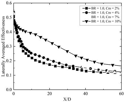
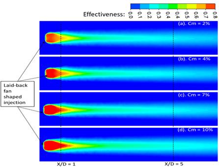
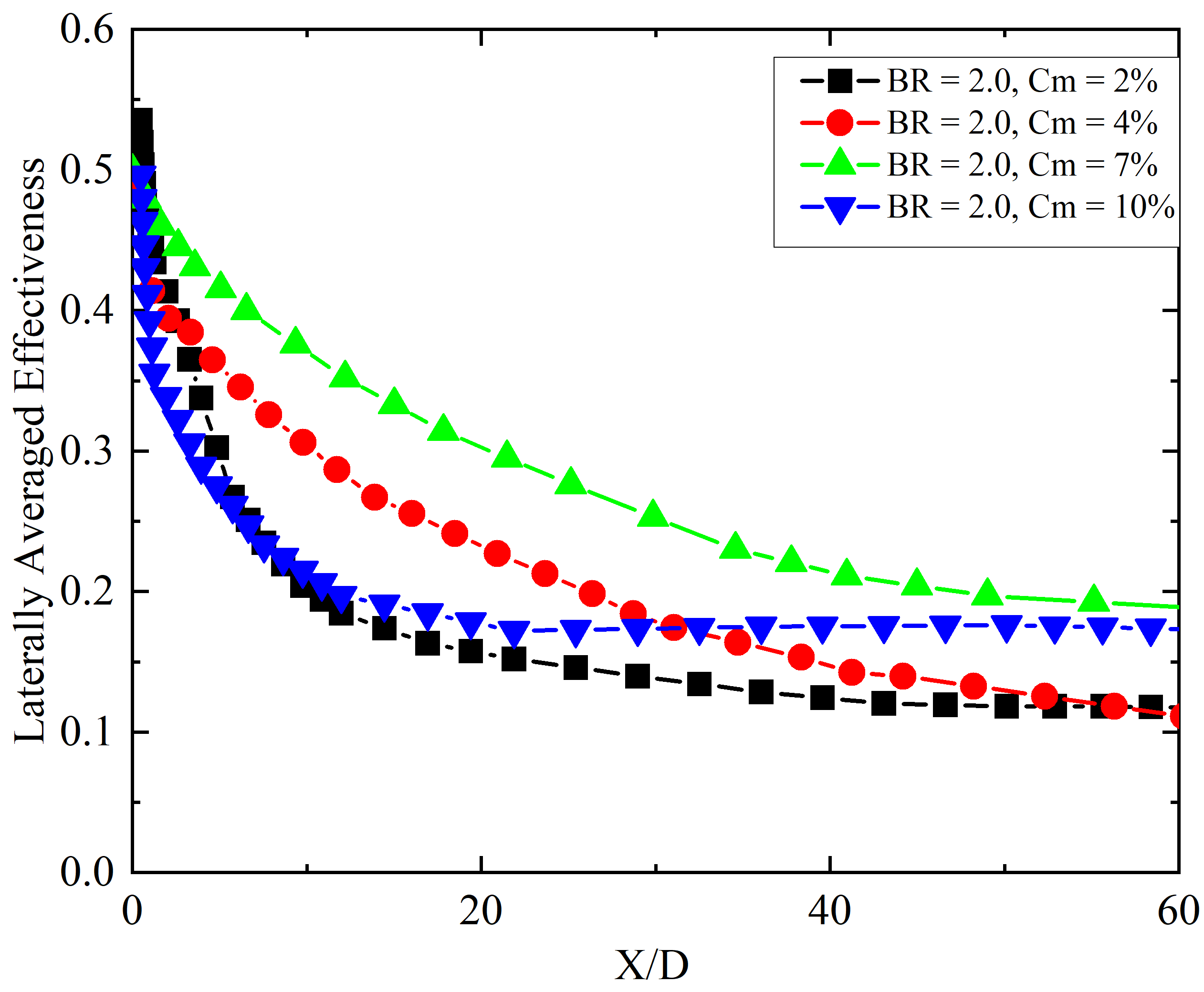
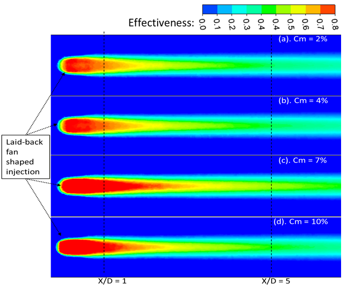
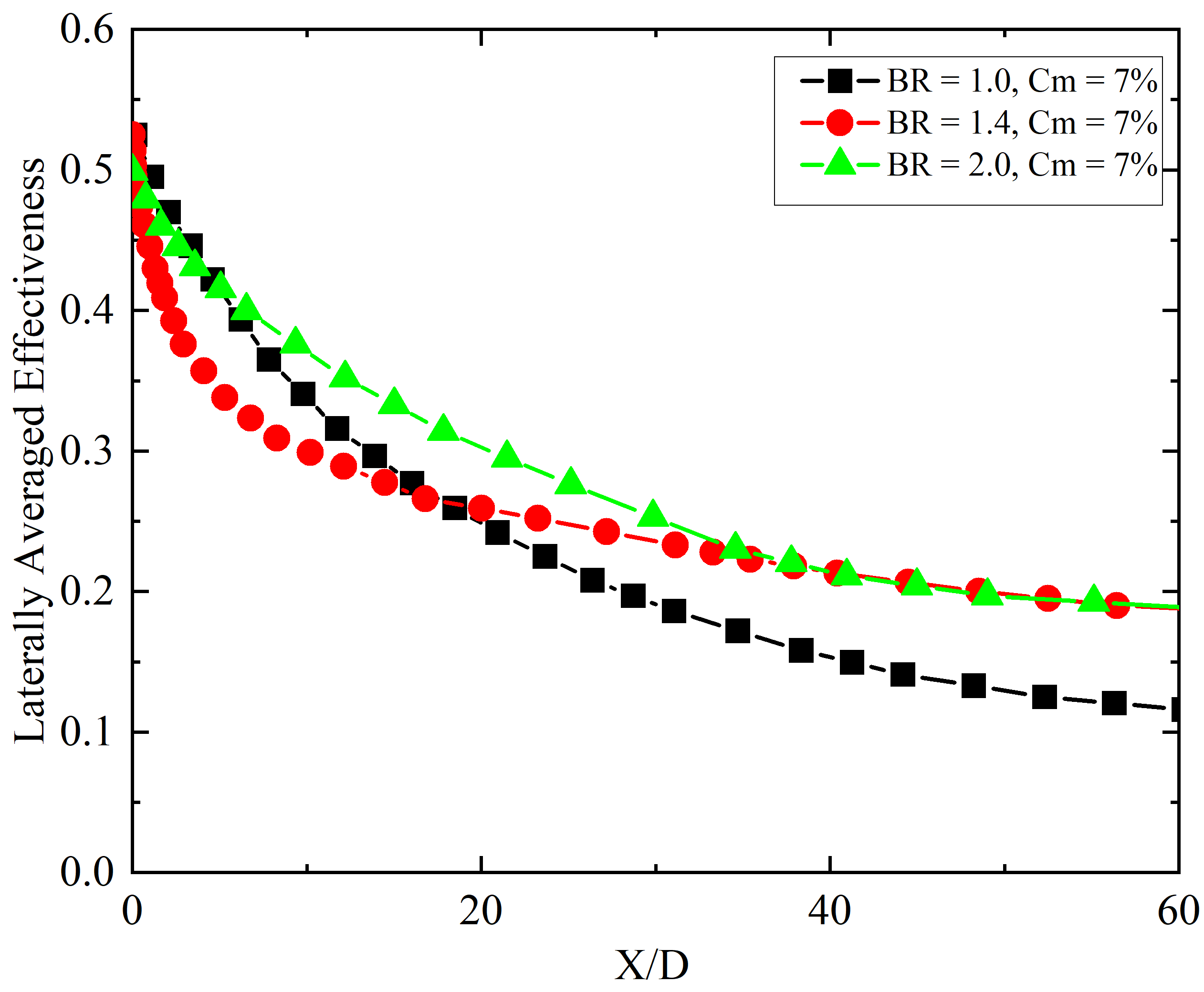
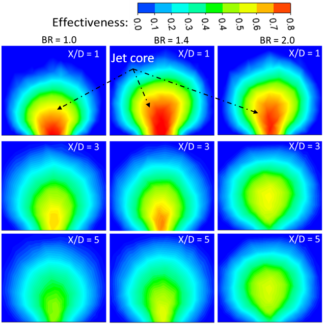
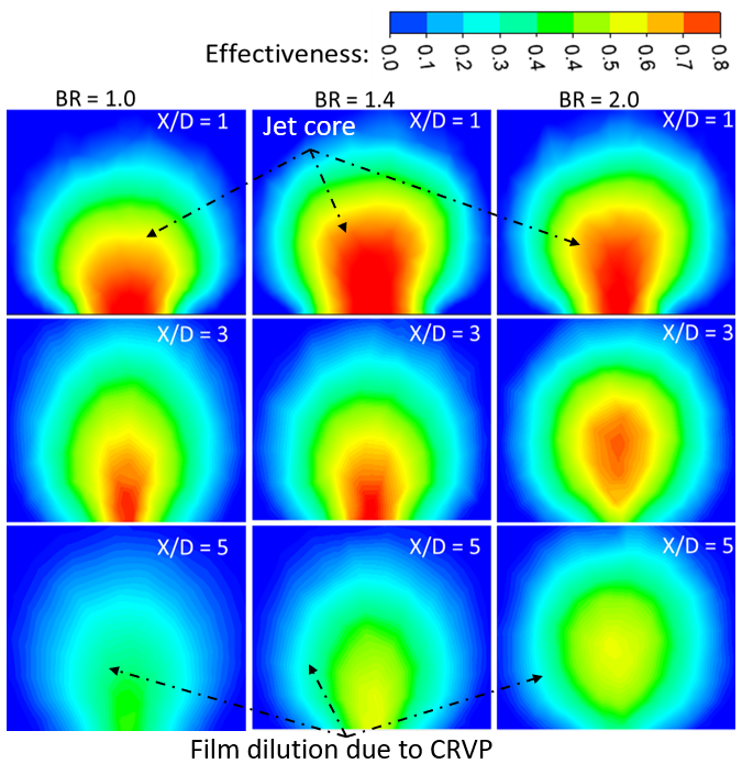
Figures 6, 8, and 10 illustrate the effect of varying mist concentrations on the laterally averaged effectiveness (LAE) of film cooling at three different blowing ratios: 1.0, 1.4, and 2.0, respectively. Figures 7, 9, and 11 provide the corresponding contour plots of local effectiveness distribution over the flat surface, extending from the injection edge to downstream regions. From the results it is evident that across all blowing ratios and mist concentrations, film cooling effectiveness consistently decreases with increasing distance from the injection hole (X/D), indicating a typical streamwise decay. This trend highlights how coolant jets gradually lose their thermal shielding capability as they mix with the hot mainstream flow. The decay of effectiveness is most rapid in the near-field region (X/D < 10) for all cases, after which the reduction becomes more gradual. This indicates that coolant mixing and dispersion are most intense immediately downstream of the injection point, while the far-field effectiveness is largely governed by the residual film core and evaporation of remaining mist droplets. In Figure 6, for BR = 1.0, LAE increased with increasing Cm. The initial effectiveness for Cm = 2% starts around 0.55 and declines gradually along X/D. Increasing Cm to 4%, 7%, and 10% leads to progressively higher initial and downstream effectiveness. However, a local phenomenon is observed within the region X/D < 10: the case with 7% mist concentration exhibits the highest LAE, even surpassing the 10% case. This behavior can be attributed to the lower momentum of the coolant jet at 7% mist concentration, which allows for greater expansion through the LFIH. The reduced jet momentum leads to a longer residence time and the retention of unevaporated droplets within the plenum. These droplets gradually evaporate downstream, enhancing cooling effectiveness near the injection point. On the other hand, the 10% mist case maintains higher cooling effectiveness over a longer streamwise distance by reducing mixing with the hot mainstream gases. In contrast, the 2% mist case, with its limited water content, results in rapid evaporation within the settling chamber, offering only short-lived near-field effectiveness. The effectiveness distribution contours in Figure 7 corroborates these findings. For Cm = 2% and 4%, the jet core is compact and remains close to the injection hole, while for Cm = 7% and 10%, a longer and more coherent jet core is observed. This extended jet core maintains high effectiveness values and remains less affected by vortex interactions, particularly important for extending the cooling coverage.
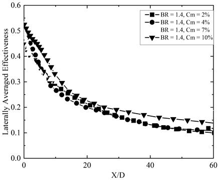
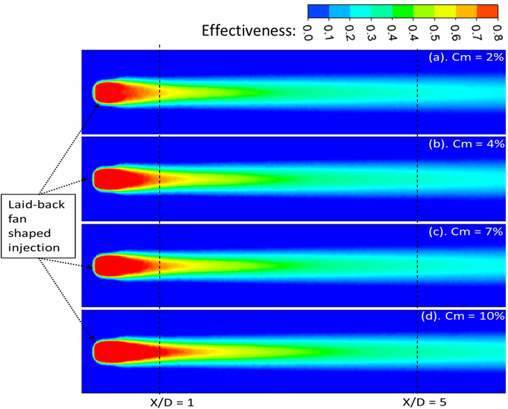
Figure 8 shows a similar trend at a slightly higher blowing ratio (BR = 1.4). The LAE increases with mist concentration, particularly up to Cm = 7%. The difference between Cm = 2%, 4%, and 7% is relatively small in the near-field (X/D < 10), with only about a 5% variation. The Cm = 10% case, however, shows the highest LAE in the near injection region up to X/D < 10, benefiting from better lateral spreading and a reduction in injection-edge recirculation due to geometric expansion. Beyond X/D = 10, the Cm = 7% case begins to outperform Cm = 10%, likely due to evaporation saturation and earlier loss of momentum in the highest mist concentration case. In Figure 9, the contour plots show a consistent trend: for Cm = 2% and 4%, the jet core is restricted to the near-hole area, while Cm = 7% and 10% provide a longer, sustained jet structure, again highlighting the advantage of moderate-to-high mist concentrations in delaying mixing and enhancing surface coverage. Figure 10 further explores the scenario at BR = 2.0. The LAE initially increases as Cm is raised from 2% to 7%, but beyond that, at Cm = 10%, there is a notable decline in cooling performance. This suggests that at higher jet momentum (due to high BR), too much mist can destabilize the jet or cause premature droplet breakup, reducing surface adherence and film integrity. The contours in Figure 11 show that for Cm = 10%, the coolant film becomes more fragmented downstream, while the Cm = 7% case maintains a more coherent structure. Thus, moderate mist concentration is more favorable at high BR, balancing the trade-off between droplet loading and aerodynamic stability.
2.3 Effect of blowing ratio
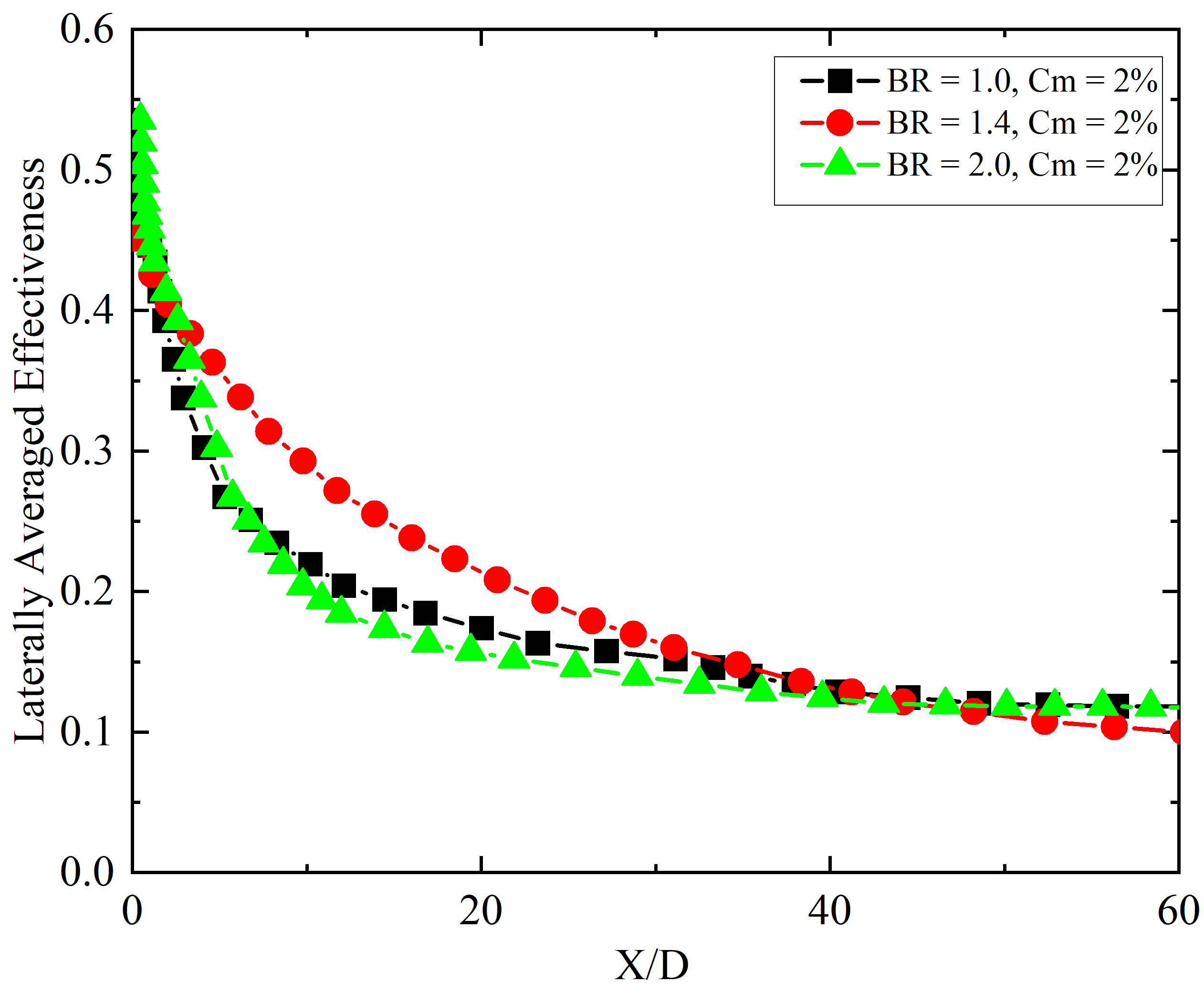
Figures 12, 13, 14, and 15 illustrate the impact of varying BR on the LAE of film cooling at constant mist concentrations of 2%, 4%, 7%, and 10%, respectively. These figures compare three different blowing ratios: 1.0, 1.4, and 2.0. Additionally, Figures 16, 17, 18, and 19 represent the effectiveness contours on the y–z plane perpendicular to the flat surface, which helps identify the cross-sectional effectiveness distribution and perpendicular shift of the film, representing the tendency of penetration of the coolant jet. In Figures 12 and 16, with a mist concentration of 2%, the LAE at all BRs is approximately the same up to X/D = 5 and gradually decreases along the streamwise direction. However, the rate of decrease in lateral film performance along X/D is slightly higher for BR = 1.0 and 2.0 compared to BR = 1.4. For most of the X/D locations, the mist film cooling at BR = 1.4 with 2% mist concentration is the highest, making BR = 1.4 the optimal value for low mist concentration cases in the laid-back fan-shaped injection configuration.
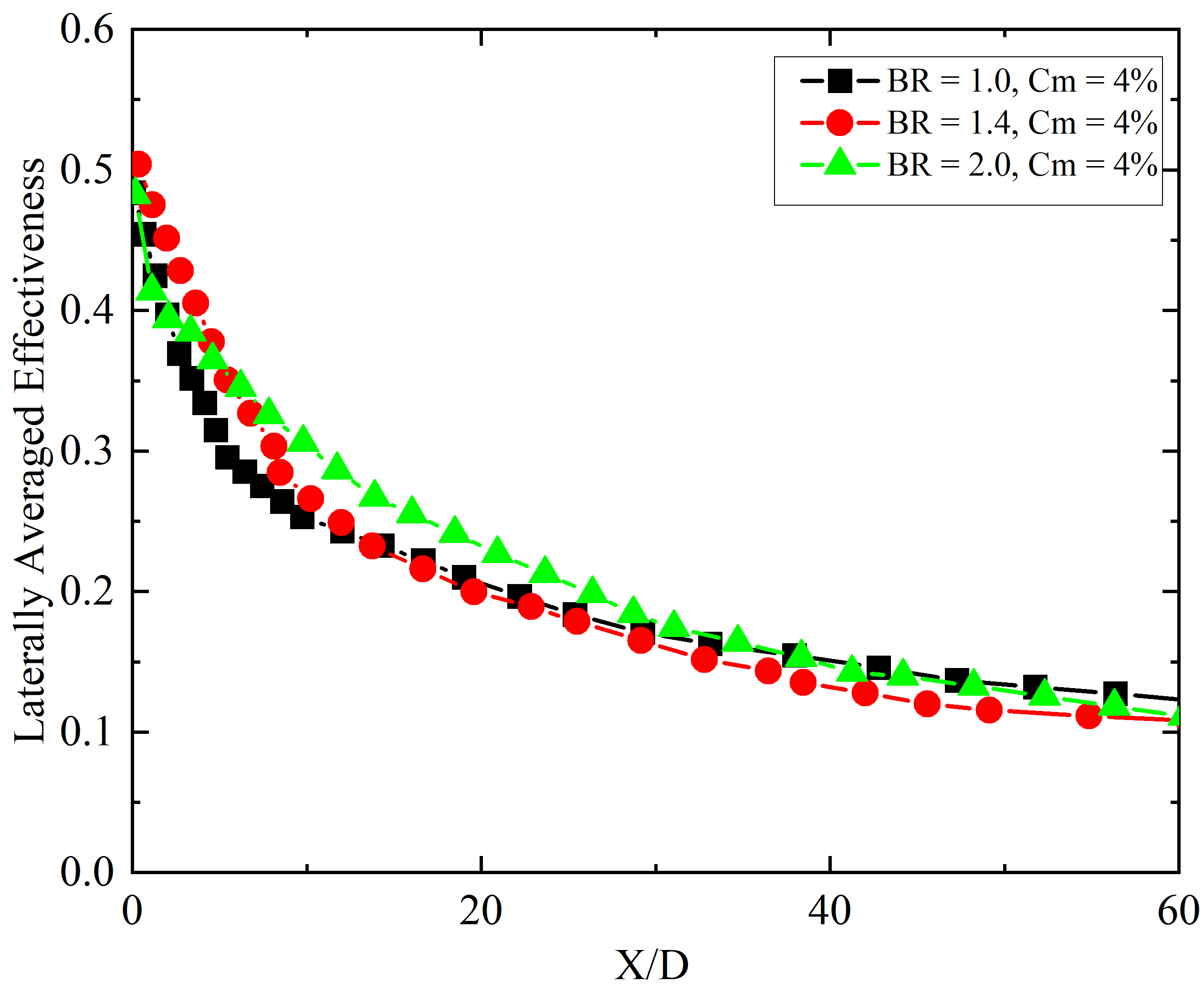
Figures 13 and 17 illustrate the LAE results for mist concentration of 4%. In the region near the injection hole and downstream of the ejection points, the LAE is higher for BR = 1.4 compared to other blowing ratios. However, as the flow progresses downstream, the rate of decrease in effectiveness for BR = 1.4 is slightly higher than for BR = 2.0. Interestingly, the percentage difference in laterally averaged effectiveness between BR = 1.0, 1.4, and 2.0 up to X/D = 15 is less than 5%, indicating a relatively small variation in performance across these blowing ratios. This suggests that while BR = 1.4 initially shows better performance near the injection point, BR = 2.0 maintains a more consistent effectiveness further downstream. Therefore, for a mist concentration of 4%, BR = 2.0 can be considered the optimal blowing ratio, as it provides a better balance of effectiveness along the entire length of the cooling surface.
In the same way, figures 14 and 18 present the observations for mist concentration of 7%. In the region near the injection hole and immediately downstream (up to X/D = 10), a lower BR of 1.0 exhibits the highest LAE compared to BR = 1.4 and BR = 2.0. As the flow advances further downstream, the LAE for BR = 2.0 continues to outperform the other BRs, maintaining a superior level of cooling effectiveness. Notably, the percentage difference in LAE between BR = 1.0, BR = 1.4, and BR = 2.0 becomes more significant, with BR = 2.0 demonstrating a clear advantage. The highest LAE observed at BR = 2.0 and Cm = 7% can be attributed to the reduced momentum of the coolant jet, which allows the droplets to remain attached to the surface for a longer duration and over a greater X/D distance. The 7% mist concentration is optimal, as it ensures sufficient pre-evaporation in the plenum, leaving only a small number of unevaporated droplets. These remaining droplets evaporate in the high-temperature zone near the coolant and hot mainstream interaction area, enhancing the cooling effectiveness. This analysis indicates that at a mist concentration of 7%, a higher blowing ratio of 2.0 is more effective in improving the cooling performance across a broader range of X/D positions. The results suggest that BR = 2.0 provides superior film coverage and improved heat transfer efficiency along the entire length of the cooling surface, making it the optimal choice for this specific mist concentration.
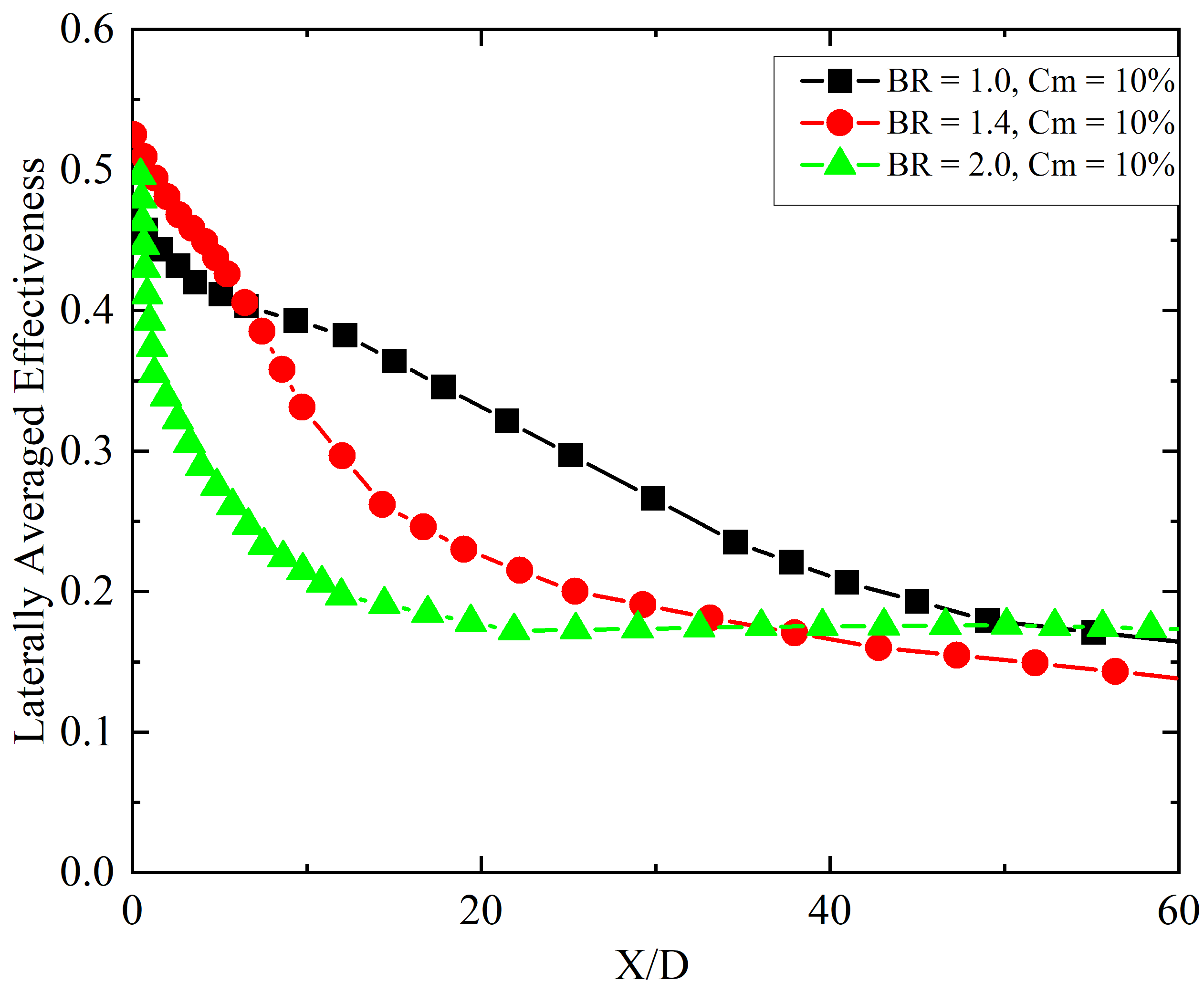
The comparison of LAE for higher Cm of 10% at various BRs is shown in Figures 15 and 19. The trend observed here is different from previous discussions. At higher mist concentrations, several factors significantly impact the cooling performance of the film. For instance, increased mist concentration elevates relative humidity in the plenum chamber, which can hinder evaporation. Consequently, many water droplets are ejected from the injection hole without evaporating, and their attachment or detachment to the surface depends on the BR. At higher BRs, such as BR = 2.0, the larger droplets have higher momentum and tend to fly away from the surface, reducing their cooling effect. Conversely, at lower BRs, such as BR = 1.0, the droplets are provided with sufficient momentum and enough time to evaporate both inside the plenum and in the mainstream region, particularly at higher Cm of 10%. When comparing the LAE of BR = 1.0 with BR = 2.0 at Cm = 10%, a peak enhancement of 50% is observed at X/D = 11.

2.4 Functional correlation for mist film cooling
To extend the applicability of the numerical results and enable predictive assessment of mist film cooling performance, an empirical correlation was developed based on the present simulation data. This correlation models the LAE as a function of the normalized streamwise distance (X/D), BR, and Cm. The developed functional form captures near-wall cooling intensity through a pre-exponential factor A(BR, Cm), and downstream decay through an exponent n(BR, Cm), as expressed below:


Physically, these correlations were derived from detailed numerical analysis of laid-back fan-shaped hole configurations. Physically, the parameter A represents the initial cooling strength near the injection region (X/D≤5), while n captures the film’s streamwise decay due to mixing and droplet evaporation. Specifically, the coefficients a0 and b0 represent the intercepts, i.e., the baseline values of A and n when both BR and Cm are zero. The terms a1 and b1 capture the isolated influence of BR, while a2 and b2 reflect the individual contribution of Cm. The interaction terms a3 and b3 account for the coupled effect of BR and Cm when varied simultaneously. Finally, a4, b4, and a5, b5, represent quadratic terms for BR and Cm, respectively, capturing any nonlinearity in the system's response. These coefficients were determined by performing regression fitting on the numerical simulation data, allowing accurate representation of the spatial decay and magnitude of mist film cooling effectiveness under different operating conditions.
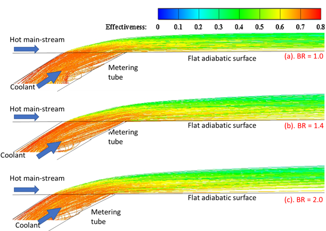
Figure 20 supports this correlation by visualizing droplet trajectories overlaid on film cooling effectiveness contours at various BRs and a fixed mist concentration of 10%. At lower BR (e.g., 1.0), droplets remain closer to the surface, promoting better near-field cooling. In contrast, at higher BR (e.g., 2.0), increased momentum causes droplet lift-off and reduced wall interaction, leading to a decline in LAE. Additionally, the correlation reveals that lower BR provides stronger but rapidly decaying cooling, whereas higher BR sustains cooling over longer distances. The interplay between mist concentration and BR also shows that optimal performance shifts depending on the balance between droplet residence time and evaporation efficiency.
The identification of optimal mist concentrations and blowing ratios for Laid-Back Fan-Shaped Injection Holes (LFIH) provides valuable guidance for engineers seeking to enhance cooling performance without significantly increasing coolant mass flow rates. Notably, the finding that a mist concentration of 7% at a blowing ratio of 2.0 delivers superior downstream effectiveness can inform the design of advanced cooling strategies for high-temperature components in gas turbines, power plants, nuclear reactors, and industrial furnaces. Furthermore, understanding the influence of vortex structures under varying flow conditions helps minimize coolant jet detachment and improve film adherence—critical for ensuring effective thermal protection in rotating machinery and high-velocity environments. By offering empirical correlations that relate geometric and flow parameters to cooling performance, this study provides practical tools that can be applied in design simulations and system optimization, ultimately supporting longer component life and improved thermal efficiency.
2.5 Area-averaged (overall) mist film cooling
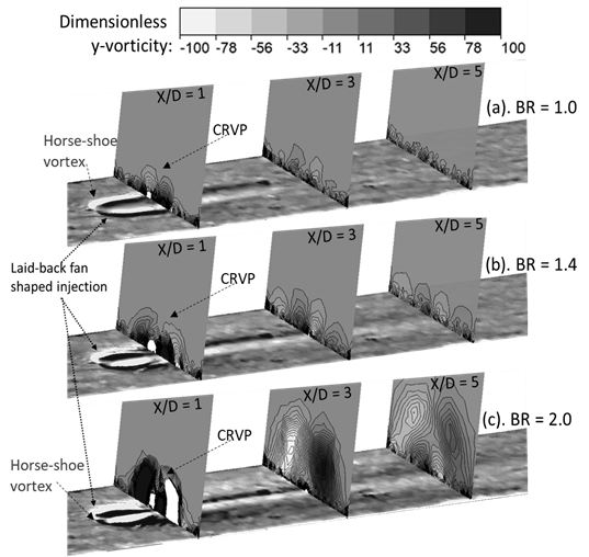
Figure 13 presents the effect of varying Cm on the area-averaged effectiveness of film cooling for three different BRs: 1.0, 1.4, and 2.0, with corresponding momentum flux ratios (MR) of 0.88, 1.72, and 3.51, respectively. The graph provides a comparative analysis of how mist concentration influences the overall cooling effectiveness across the entire surface area. For each BR, the variation in the area-averaged effectiveness of the mist film is less than 5%. This minimal variation can be attributed to the low quantity of water droplets in the carrier phase (air) and their evaporation within the plenum chamber. Consequently, there is a reduced likelihood of droplets reaching the injection hole to further cool the flat surface. As a result, the coolant mixture behaves almost like a dry air-cooling system, leading to a consistent area-averaged effectiveness across different mist concentrations. Increasing the mist concentration to 4% does not result in a significant change in the area-averaged effectiveness. However, at this mist concentration, a decrease in area-averaged effectiveness is observed for each BR. The most notable reduction is for BR = 1.4, with a maximum decrease of 17%. At a Cm of 7%, there is a notable variation in area-averaged effectiveness with changes in the BR. The data reveals that the highest area-averaged effectiveness is achieved with a BR of 1.4, whereas the lowest effectiveness is recorded with a BR of 1.0. When comparing the area-averaged effectiveness of BR = 1.4 with BR = 1.0, a 17% enhancement is observed for BR = 1.4. This significant improvement can be attributed to several factors associated with the optimal BR of 1.4. In the case of laid-back fan-shaped injection holes, a BR of 1.4 offers a balanced momentum for the coolant jet, facilitating better film adhesion and lateral spreading across the surface. Moreover, at Cm =7%, the mist concentration is sufficient to provide a substantial cooling effect without causing excessive droplet coalescence or premature evaporation. The increased mist concentration enhances the cooling potential by leveraging the latent heat of vaporization, which is maximized at an optimal BR. The higher area-averaged effectiveness at BR = 1.4 also indicates an optimal interaction between the coolant jet and the mainstream flow. This interaction is crucial for maintaining a stable and effective cooling film, which is less likely to be disrupted by vortices or turbulent eddies. In contrast, at BR = 1.0, the lower momentum of the coolant jet may not provide sufficient force to maintain an effective cooling film, leading to reduced cooling performance. At higher mist concentrations of 10%, the area-averaged effectiveness decreases for BR = 1.4 and 2.0, with the lowest effectiveness observed for BR = 2.0. This reduction can be attributed to increased relative humidity, which inhibits the evaporation of droplets. The unevaporated droplets, due to their higher momentum at BR = 2.0, penetrate into the mainstream and are carried away without contributing to the cooling effect. Conversely, BR = 1.0 maintains sufficient momentum to allow droplets to evaporate effectively within the plenum and the mainstream regions, thereby enhancing the cooling performance. To further explore the mechanisms governing cooling effectiveness, the present study utilizes Equations 31 and 32 to evaluate the vorticity (ω) and its y-directional component (ωy) for analyzing vortex structures as shown in figure 22. These are defined as dimensionless ωy∘ as [38]:
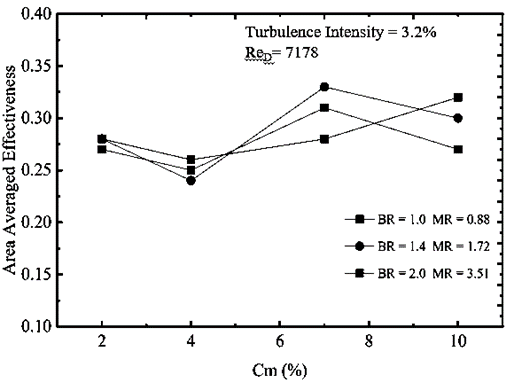
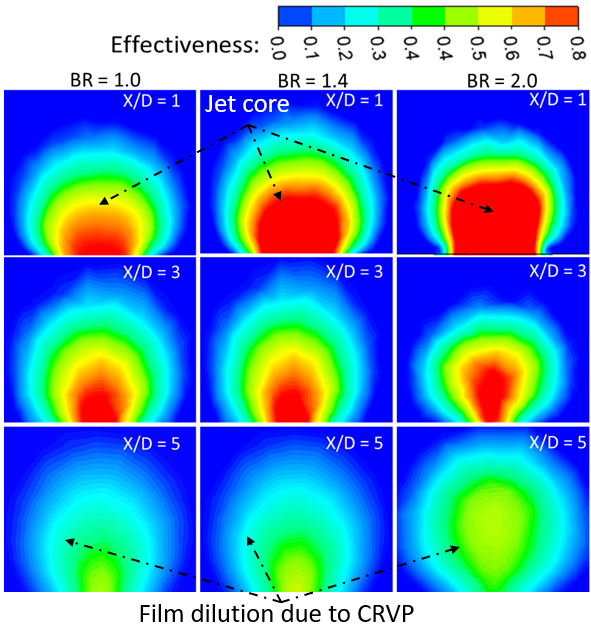
Figure 22 shows vortical structures, including hanging vortices near the trailing and lateral edges of the LFIH. These vortices exhibit alternating signs of y-vorticity, with relatively low vorticity between them, leading to reduced mixing and narrower lateral dispersion. At lower BRs (e.g., 0.2 and 0.6), this behavior allows the coolant to spread laterally over short streamwise distances. As BR increases, the CRVPs elongate, and at BR = 2.0, secondary CRVPs are also observed above the main vortex cores. These CRVPs are associated with high-mixing zones that promote lateral separation of the coolant film, resulting in a thinner film near the hole exits for BR = 1.4 and 2.0. The findings highlight that vortex formation directly impacts coolant dispersion, BR = 2 promotes wider lateral spreading via edge vortices, while BR = 1 induces complex interactions involving CRVPs and tube vortices that significantly affect mixing behavior and cooling performance.
3 Conclusion
This study comprehensively investigates the effects of Cm and BR on the performance of film cooling using LFIH. Through detailed numerical simulations and a series of analyses, the intricate interplay between these variables was examined, providing valuable insights into optimizing film cooling effectiveness. The findings reveal that both mist concentration and blowing ratio significantly influence the laterally and area-averaged effectiveness of film cooling. Higher mist concentrations generally enhance cooling performance, but the extent of this improvement varies with the blowing ratio. The results highlight the critical role of optimizing these parameters to achieve the best cooling performance, particularly in high-temperature applications. Key conclusions and observations include:
- At BR = 1.0, increasing mist concentrations enhance LAE, with 10% mist showing the highest effectiveness. BR = 1.4 is optimal for moderate mist concentrations (7%), while BR = 2.0 improves LAE up to 7% mist but decreases at 10%.
- At Cm = 7%, BR = 2.0 achieves the highest LAE, especially in the downstream region, due to reduced momentum allowing droplets to stay attached to the surface longer, enhancing cooling performance.
- At Cm = 7%, a BR of 1.4 achieves the highest area-averaged effectiveness, showing a 17% improvement due to the balanced momentum ensuring better film adhesion and lateral spreading.
- At higher Cm = 10%, the area-averaged effectiveness decreases for higher BRs of 1.4 and 2.0. The reduction is attributed to higher momentum causing unevaporated droplets to penetrate the mainstream.
- A lower BR of 1.0 maintains sufficient momentum for effective droplet evaporation, enhancing cooling performance and benefiting better area-averaged effectiveness at Cm = 10%.
- At low mist concentrations (Cm ≤ 4%), area-averaged effectiveness remains nearly constant across BRs due to early droplet evaporation, resembling dry air cooling. At Cm = 7%, BR = 1.4 shows a 17% improvement over BR = 1.0, indicating optimal jet momentum for film adherence and efficient mist utilization.
- Moderate BRs (0.6–1.4) form stable CRVPs for effective lateral spreading, while high BR = 2.0 introduces secondary vortices that disrupt film continuity and reduce cooling by enhancing droplet escape. This highlights the importance of selecting an optimal BR.
References
[1] Ekkad, S., and Han, J. C., 2015, “A Review of Hole Geometry and Coolant Density Effect on Film Cooling,” Front. Heat Mass Transf., 6(1), pp. 1–14. View Article
[2] Dhungel, A., Lu, Y., Phillips, W., Ekkad, S. V., and Heidmann, J., 2009, “Film Cooling From a Row of Holes Supplemented With Antivortex Holes,” J. Turbomach., 131(2), p. 021007. View Article
[3] Ekkad, S. V, Zapata, D., and Han, J. C., 1997, “Film Effectiveness Over a Flat Surface With Air and CO2 Injection Through Compound Angle Holes Using a Transient Liquid Crystal Image Method,” J. Turbomach., 119(3), pp. 587–593. View Article
[4] Gritsch, M., Schulz, A., and Wittig, S., 2011, “Discharge Coefficient Measurements of Film-Cooling Holes With Expanded Exits,” J. Turbomach., 120(3), p. 557. View Article
[5] Zhou, J., Wang, X., Li, J., and Lu, H., 2017, “CFD Analysis of Mist/Air Film Cooling on a Flat Plate with Different Hole Types,” Numer. Heat Transf. Part A Appl., 71(11), pp. 1123–1140. View Article
[6] Mhetras, S., Han, J.-C., and Rudolph, R., 2008, “Film-Cooling Effectiveness From Shaped Film Cooling Holes for a Gas Turbine Blade,” (June 2008), pp. 837–848. View Article
[7] Haydt, S., Lynch, S., and Lewis, S., 2018, “The Effect of Area Ratio Change Via Increased Hole Length for Shaped Film Cooling Holes With Constant Expansion Angles,” J. Turbomach., 140(5). View Article
[8] Saumweber, C., and Schulz, A., 2012, “Free-Stream Effects on the Cooling Performance of Cylindrical and Fan-Shaped Cooling Holes,” J. Turbomach., 134(6), p. 061007. View Article
[9] Haydt, S., Lynch, S., and Lewis, S., 2018, “The Effect of Area Ratio Change via Increased Hole Length for Shaped Film Cooling Holes with Constant Expansion Angles,” J. Turbomach., 140(5). View Article
[10] Hodges, Craig P. Fernandes, E. F., 2019, “Flow Statistics and Visualization of Multirow Film Cooling Boundary Layers Emanating from Cylindrical and Diffuser Shaped Holes,” J. Turbomach., 141(6). View Article
[11] Schroeder, R. P., and Thole, K. A., 2016, “Effect of High Freestream Turbulence on Flowfields of Shaped Film Cooling Holes,” J. Turbomach., 138(9), pp. 1–11. View Article
[12] Ghorab, M. G., 2014, “Film Cooling Effectiveness and Heat Transfer Analysis of a Hybrid Scheme with Different Outlet Configurations,” Appl. Therm. Eng., 63(1), pp. 200–217. View Article
[13] Haydt, S., and Lynch, S., 2019, “Cooling Effectiveness for a Shaped Film Cooling Hole at a Range of Compound Angles,” J. Turbomach., 141(4), p. 41005. View Article
[14] Wright, L. M., McClain, S. T., and Clemenson, M. D., 2011, “Effect of Density Ratio on Flat Plate Film Cooling With Shaped Holes Using PSP,” J. Turbomach., 133(4), p. 041011. View Article
[15] Gritsch, M., Schulz, A., and Wittig, S., 1998, “Adiabatic Wall Effectiveness Measurements of Film-Cooling Holes With Expanded Exits,” J. Turbomach., 120(3), pp. 549–556. View Article
[16] Singh, K., Premachandran, B., and Ravi, M. R., 2017, “Experimental and Numerical Studies on Film Cooling with Reverse/Backward Coolant Injection,” Int. J. Therm. Sci., 111(September), pp. 390–408. View Article
[17] Oliver, T. A., Bogard, D. G., and Moser, R. D., 2019, “Large Eddy Simulation of Compressible, Shaped-Hole Film Cooling,” Int. J. Heat Mass Transf., 140, pp. 498–517. View Article
[18] Mallikarjuna Rao, P., Biswal, P., and Prasad, B. V. S. S. S., 2018, “A Computational Study of Mist Assisted Film Cooling,” Int. Commun. Heat Mass Transf. View Article
[19] Wang, J., Vujanovic, M., and Sunden, B., 2018, “A Review of Multiphase Flow and Deposition Effects in Film-Cooled Gas Turbines,” Therm. Sci. View Article
[20] Kim, K. H., Ko, H. J., Kim, K., and Perez-Blanco, H., 2012, “Analysis of Water Droplet Evaporation in a Gas Turbine Inlet Fogging Process,” Appl. Therm. Eng., 33–34(1), pp. 62–69. View Article
[21] Li, X., and Wang, T., 2006, “Simulation of Film Cooling Enhancement With Mist Injection,” J. Heat Transfer, 128(6), pp. 509–519. View Article
[22] Ragab, R., and Wang, T., 2017, “An Experimental Study of Mist/Air Film Cooling With Fan-Shaped Holes on an Extended Flat Plate—Part 1: Heat Transfer,” J. Heat Transfer, pp. 1–12. View Article
[23] Jiang, Y., Zheng, Q., Dong, P., Yao, J., Zhang, H., and Gao, J., 2015, “Conjugate Heat Transfer Analysis of Leading Edge and Downstream Mist-Air Film Cooling on Turbine Vane,” Int. J. Heat Mass Transf., 90, pp. 613–626. View Article
[24] Kim, J. H., and Kim, K. Y., 2018, “Film-Cooling Performance of Converged-Inlet Hole Shapes,” Int. J. Therm. Sci., 124(May 2017), pp. 196–211. View Article
[25] Wang, T., and Li, X., 2008, “Mist Film Cooling Simulation at Gas Turbine Operating Conditions,” Int. J. Heat Mass Transf., 51(21–22), pp. 5305–5317. View Article
[26] Kumari, N., Bahadur, V., Hodes, M., Salamon, T., Kolodner, P., Lyons, A., and Garimella, S. V., 2010, “Analysis of Evaporating Mist Flow for Enhanced Convective Heat Transfer,” Int. J. Heat Mass Transf., 53(15–16), pp. 3346–3356. View Article
[27] Nowak, G., Wróblewski, W., and Nowak, I., 2012, “Convective Cooling Optimization of a Blade for a Supercritical Steam Turbine,” Int. J. Heat Mass Transf., 55(17–18), pp. 4511–4520. View Article
[28] Li, X., Gaddis, J. L., and Wang, T., 2003, “Mist/Steam Cooling by a Row of Impinging Jets,” Int. J. Heat Mass Transf., 46(12), pp. 2279–2290. View Article
[29] Li, X., Gaddis, J. L., and Wang, T., 2003, “Mist/Steam Heat Transfer With Jet Impingement Onto a Concave Surface,” J. Heat Transfer, 125(3), pp. 438–446. View Article
[30] Wang, T., and Dhanasekaran, T. S., 2011, “Model Verification of Mist/Steam Cooling With Jet Impingement Onto a Concave Surface and Prediction at Elevated Operating Conditions,” J. Turbomach., 134(2), p. 021016. View Article
[31] Zhao, L., and Wang, T., 2014, “An Experimental Study of Mist/ Air Film Cooling on a Flat Plate with Application to Gas Turbine Airfoils-Part I: Heat Transfer,” J. Turbomach., 136(7), pp. 1–9. View Article
[32] Zhao, L., and Wang, T., 2014, “An Experimental Study of Mist/Air Film Cooling on a Flat Plate with Application to Gas Turbine Airfoils-Part II: Two-Phase Flow Measurements and Droplet Dynamics,” J. Turbomach., 136(7), pp. 1–9. View Article
[33] Zhang, R., Song, Y., Han, S., Zhou, L., Li, L., Zhang, H., and Du, X., 2022, “Film Cooling Performance Enhancement of Serrate-Type Trenched Cooling Holes by Injecting Mist into the Cooling Air,” Int. J. Therm. Sci., 179(April), pp. 1–16. View Article
[34] Singh, K., Premachandran, B., and Ravi, M. R., 2016, “Experimental Assessment of Film Cooling Performance of Short Cylindrical Holes on a Flat Surface,” Heat Mass Transf. und Stoffuebertragung, 52(12), pp. 2849–2862. View Article
[35] Morsi, S. A., and Alexander, A. J., 1972, “An Investigation of Particle Trajectories in Two-Phase Flow Systems,” J. Fluid Mech., 55(2), pp. 193–208. View Article
[36] Wang, T., and Ragab, R., 2014, “Investigation of Applicability of Transporting Water Mist for Cooling Turbine Blades,” p. V05AT12A021. View Article
[37] Ragab, R., and Wang, T., 2017, “An Experimental Study of Mist/Air Film Cooling with Fan-Shaped Holes on an Extended Flat Plate - Part 2: Two-Phase Flow Measurements and Droplet Dynamics.” View Article
[38] Kanani, H., Shams, M., and Ebrahimi, R., 2009, “Numerical Modelling of Film Cooling with and without Mist Injection,” Heat Mass Transf. und Stoffuebertragung, 45(6), pp. 727–741. View Article