Journal of Fluid Flow, Heat and Mass Transfer (JFFHMT)
ISSN: 2368-6111

Volume 12 - Year 2025 - Pages 162-169
DOI: 10.11159/jffhmt.2025.018
Comparative Analysis of Heat Release and Flame Quenching in Fuel Jet and Premixed Flames Across Multiple Fuels
Derek Bradley1, Tawfiq Abdul-Aziz-Al-Mughanam2, Adriana Palacios3,*
1University of Leeds, School of Mechanical Engineering,
Leeds, LS29JT, UK.
D.Bradley@leeds.ac.uk
2King Faisal University, Department of Mechanical Engineering, College of Engineering,
P.O. Box 380, Al-Ahsa 31982, Saudi Arabia.
talmughanam@kfu.edu.sa
3Universidad de las Americas, Puebla, Department of Chemical, Food and Environmental Engineering,
Puebla, 72810, Mexico.
*Corresponding author: adriana.palacios@udlap.mx
Abstract - The paper compares and contrasts heat release and flame quenching in both jet and premixed flames. Atmospheric jet flame heat release rates of a variety of fuels at blow-off are first discussed. It also reports burning data on less reactive fuels in a small 3 mm diameter pipe. Further analysis of an atmospheric methane jet flame reveals it to require a significantly greater volume for a given heat release rate than a stoichiometric premixed atmospheric methane-air flame. It is also shown that H2 and C2H2 exhibit high reactivity in both types of flame, and the heavier hydrocarbons exhibit low reactivity. A generalised, dimensionless, correlation of atmospheric flame blow-off data, covering many fuels, is the source of data for the derivation of practical values of heat release rates, at different such velocities on the 3 mm diameter pipe. This mathematical modelling and the experiments explore the differences between fuel jet and premixed combustion, and enable volumetric heat release rates to be evaluated and compared. The greater control that is possible with premixed flames makes for more compact combustion. It was found that the volumetric heat release rate of a methane atmospheric jet flame was 8.2 MW/m3, whilst an optimal design of a more compact premixed burner design resulted in a significantly higher value of 416 MW/m3. There are, nevertheless, strong underlying similarities in flame structures between jet and premixed flames, revealed through the propagation parameters, Ub* and K, and the quenching parameters, Db/δk and dk/δk. A Quench Diagram shows quench lines for different fuels, below which flame quenching occurs, and above which flames can propagate.
Keywords: Blow-off, Jet flames, Premixed flames, Volumetric heat release rate, Quenching of flames.
© Copyright 2025 Authors - This is an Open Access article published under the Creative Commons Attribution License terms Creative Commons Attribution License terms. Unrestricted use, distribution, and reproduction in any medium are permitted, provided the original work is properly cited.
Date Received: 2025-01-10
Date Revised: 2025-04-29
Date Accepted: 2025-05-06
Date Published: 2025-05-08
1. Introduction
Over the past decade, extensive research has been dedicated to elucidating the physical mechanisms that govern blowout phenomena—an area of critical importance in fire risk assessment and combustion science—with the goal of effectively managing the progression from turbulent jet fires to combustion explosions [1]-[6]. In these studies, particular attention has been paid to how a high-velocity fuel jet entrains ambient air: as the jet issues from its nozzle, a central reactive mixture forms near the leading edge where the composition closely matches the conditions for maximum laminar burning velocity, SL. However, if the jet entrains too much incompletely mixed air, the flame can become quenched, underscoring the dominant role of fuel velocity in determining the jet flame’s heat release rate. To capture this behaviour quantitatively, previous computational and experimental work [7]–[9] has introduced the dimensionless Flow Number, U*, defined as:
U* has a primary influence on blow-off and (δk/D) upon pipe flame quenching. Plots of δk/Db against U* summarise the blow-off data for many different fuels and their blends, as shown below in Figure 1. The ratio of stagnation pressure to exhaust pressure arises from the expansion of the fuel to the pipe exit plane with a Mach number, M, and is given by:
To derive δk, the methodology of Gӧttgens et al. [10] is employed. This involves identifying an inner layer temperature To, below which no reaction occurs. It is shown how the pipe diameter influences the blow-off velocity from the pipe for different fuels. The data in Figure 1 are used to show the blow-off velocities from a 3 mm diameter pipe and their different heat release rates.
The present research work aims to systematically compare the heat release rates and flame quenching characteristics of jet and premixed flames across a wide range of fuels, using experimental data and mathematical modelling. By employing a generalized, dimensionless correlation of blow-off data and evaluating the influence of pipe diameter and flow parameters on combustion behaviour, this study provides a unified framework to quantify and contrast volumetric heat release rates in both combustion regimes. The novelty of this research lies in its comprehensive approach to linking practical blow-off velocities with heat release rates for multiple fuels in small-diameter pipes—an area where prior studies have been limited. Furthermore, the introduction of quenching diagrams for various fuels offers a new tool for understanding flame stability thresholds, which is critical for the design of compact and efficient combustion systems.
2. Atmospheric Jet Flame Blow-off Characteristics
The generalised correlation in Figure 1 of inversely normalised pipe diameter plotted against Flow Number is a rich source of information on the blow-off of atmospheric jet flames, to which data for NH3/H2 blends and acetylene, ethylene, and ethane have been added [9], [11]-[13].
The required hydrogen and hydrocarbon thermo-physical and isentropic expansion data were obtained from the GasEq Code [14]. For the ammonia-hydrogen blend, (XaNH3 + H2), Xa is the molar fraction of ammonia in the blend. The NH3 induces slower burning and increases the flame thickness. Such a decrease in reactivity necessitates a larger pipe diameter and a lower fuel velocity for flame survival. The atmospheric jet flame combustion regimes for different fuels, defined by the ratio δk/Db and illustrated in Figure 1, can be translated into more practical parameters, for example, how the fuel blow-off velocity varies with pipe diameter. This is shown in Figure 2 for a range of mixtures, including the ammonia–hydrogen blends.
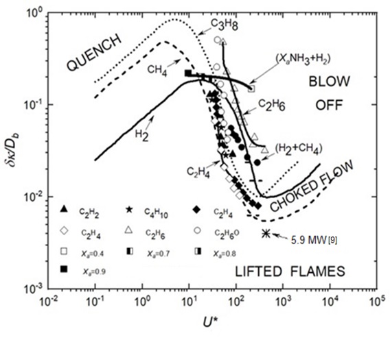
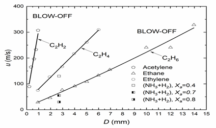
Figure 2 shows linear variations of blow-off velocity with pipe diameter and the diverse behaviour of fuels. With quite small pipe diameters, because of its high reactivity, C2H2 can attain high velocities and high heat release rates, whereas the less reactive fuels require larger pipe diameters and lower velocities. For the ammonia-hydrogen blend, (XaNH3 + H2), an increase in which induces slower burning, necessitating larger pipe diameters.
A practical characteristic of a fuel is its heat release rate, just before blow-off. Such data were derived for ten different fuels and are shown in Figure 3. The heat release rates are plotted against the jet blow-off velocity from a 3 mm diameter pipe. These and other data are listed for each of the ten contrasting fuels in Table 1. They are arranged in decreasing order of the heat release rates at blow-off. An interesting aspect is the way the heat release rate points follow a general trend, culminating in high heat release rates from hydrogen, acetylene, and propane.
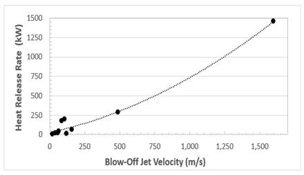
There were some problems in deriving accurate values of laminar flame thickness, δk, but there was an approximate trend for them to decrease with increasing heat release rate. Table 1 shows the exceptional reactive qualities of hydrogen. Along with acetylene, it has a high heat release rate, a high blow-off velocity, and a low air/fuel mole ratio. Its reactions involve high diffusivity H2 and H. These generate rapid chain branching through H + O2 = OH + O, which is further enhanced by the absence of lethargic C atoms and CO + OH = CO2 + H. Large values of D can avoid extinction and can be used in the flaring of large volumes of flammable gas. The associated large energy release rate of 5.9 MW at the asterisked point [15] on Figure 1 is attributable to a possible venting and subsequent flaring of H2 following a major hypothetical nuclear reactor failure.
Table 1. Heat release rates and Blow-off Velocities from a 3 mm diameter pipe for ten fuels.
|
Fuel |
Blow-Off Jet Velocity, u, m/s |
Heat Release Rate, kW, at Blow-Off |
Stoichiometric Air/Fuel Mole Ratio |
Laminar Flame Thickness, δk, mm [Reference] |
|
Hydrogen |
1,600 |
1,460.1 |
2.38 |
0.0399 [9] |
|
Acetylene |
489 |
286.035 |
11.95 |
0.02754 [9] |
|
Propane |
108 |
200.1005 |
23.81 |
0.10045 [9] |
|
Butane |
86 |
171 |
31 |
0.60 [12] |
|
Ethylene |
160 |
65.06 |
14.29 |
0.062198 [9] |
|
Ethane |
67 |
38 |
16.7 |
0.275 [13] |
|
Di-methyl Ether |
41 |
16 |
16.7 |
- |
|
Methane |
58 |
15.13 |
9.52 |
0.1288 [9] |
|
NH3/H2, Xa=0.4 |
120 |
9.77 |
- |
- |
|
NH3/H2, Xa=0.8 |
20 |
1.84 |
- |
- |
These findings are strongly supported by the integration of both experimental measurements and theoretical calculations, which together offer a consistent understanding of flame behaviour across various fuel types. The use of dimensionless correlations, such as δk/Db versus Flow Number, allows for a clear interpretation of how thermo-physical properties and combustion kinetics govern flame stability and blow-off tendencies. In particular, the variations observed between highly reactive fuels like hydrogen and acetylene, and less reactive fuels such as ammonia-hydrogen blends, are convincingly explained by differences in laminar flame speed, diffusivity, and chain-branching mechanisms. The methodology employed to derive laminar flame thicknesses and the careful application of isentropic expansion relationships ensure that the derived blow-off velocities and heat release rates are grounded in sound physical principles. Furthermore, the practical implications of these results are emphasized by the demonstration that fuel choice and burner geometry can be strategically manipulated to optimize combustion stability and efficiency. This comprehensive and methodical approach not only validates the presented data but also enhances its applicability for real-world burner and flare design.
3. Jet Flame Structure
Although Table 1 presents a useful listing of relative fuel reactivities, it is inadequate for the detailed understanding of the design of jet flames, as it lacks any indication of flame stability and the volume necessary to attain the heat release rate. To attain this level of understanding, an atmospheric CH4 jet was analysed in detail. In [8], the jet, after leaving a vertical pipe of diameter D = 0.005 mm, with a velocity of 28 m/s, the flow created a vertical jet flame. The CH4 initial density was 0.657 kg/m3 and the heat of reaction 55.5 MJ/kg, yielding an adiabatic flame plume with a heat release rate of 20.05 kW, if combustion were to be completed. The actual bounds of the jet fire plume boundary were defined by thermocouple temperature measurements, about 800 K at the boundary, along with infrared emissions. These revealed a cylindrical plume height of 0.67 m. and a diameter of 0.068 m, with a volume of 0.002433 m3.
At the leading edge of the fuel jet, there is sufficient air entrainment to generate a reactive mixture there. At the core of the jet, the limited air supply inhibits combustion, as does the limited fuel supply at the edges of the jet. There could also be unburned fuel and intermediates within the plume. The mixture could be outside the limit of flammability. No allowance is made for this. Similarly, no allowance is made for radiative energy loss.
The heterogeneity of the mixture generates spatial contours of heat release rates and streamlines. From these, the numerical analyses suggested that for methane and propane, at different jet velocities, within the overall plume volume, only between 0.13 and 0.29 of it was a reaction zone releasing heat. For the present CH4 conditions, this fraction was 0.17. This fraction is relevant to the question of how fast we can burn, a question that has usually evoked a premixed response [16]-[18]. Here, it is proposed to compare this theoretical study of the volumetric heat release rate in a methane jet plume flame with that of the same fuel in a premixed flame.
This detailed analysis is crucial because it highlights how both fuel properties and jet configuration fundamentally influence combustion characteristics and efficiency. The relatively small reactive volume fraction (only 17% of the plume for methane under the given conditions) underscores the inherent limitations of jet flames in achieving compact and efficient combustion compared to premixed systems. By quantifying these spatial constraints, the study provides a clearer rationale for why premixed flames, which allow for homogeneous fuel-air mixtures before ignition, can achieve substantially higher volumetric heat release rates. Furthermore, the methodology—combining thermocouple measurements, infrared emissions, and numerical simulations—ensures robust cross-validation of the observed plume dimensions and reactive zones. These layered approaches justify the comparison between jet and premixed flames and strengthen the argument that design optimizations must carefully balance reactivity, air entrainment, and flame stability to maximize energy release and minimize unburned intermediates.
4. Premixed Flame Structure
Jet flame control is less complex than that required for premixed flames, for which there are more controllable, well-defined parameters. These include equivalence ratios, turbulent length scales, turbulent velocities, burning velocities, Reynolds, Karlovitz, Lewis, and Markstein numbers. For the present study, a key relationship is the ratio of mass-based turbulent burning velocity to the effective turbulent velocity acting on the flame front, given by U = ut/uk. This also depends upon the Markstein number of the mixture, Masr, and the Karlovitz stretch Factor, K. This can be regarded as a ratio of chemical lifetime, (δk/ul), to eddy lifetime, (λ/u’), which yields [19]:
with RL, the turbulent Reynolds number.
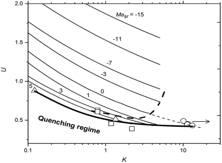
Through the more complete control that can be exerted over the mixing and combustion in premixed combustion, higher values of volumetric heat release rate can be attained. The inter-relationships of these key turbulent parameters are given in Figure 4, from [20]. This shows U as a function of K for different values of Masr, the values of which decrease with increasing pressure [21]. This relationship is partly evaluated from measurements of turbulent burning velocities in fan-stirred explosions. It is the basis for the selection of an appropriate turbulent premixture to compare with the jet flame. A modest turbulent burning velocity of 1 m/s was selected with ul = 0.36 m/s and Masr = 4.2 [21]. A selected rms turbulent velocity u’ of 1 m/s gave U = 1. With an appropriate turbulent integral length scale, L, of 0.007 m, which, with the aid of [14], gave RL = 437. From Eq. 3, these values yielded K = 0.1. The resulting selection of Masr=4.2, U=1, and K=0.1 is marked by the asterisk in Figure 4.
The premixed combustion is envisaged as being stabilised on a flat flame burner, with prior simultaneous mixing and turbulising of the fuel and air in upward flow, through grids, followed by reaction in the burner [22],[23]. A diameter of 40 mm is appropriate for the burner and the flat flame, with a flow velocity equal to the turbulent burning velocity of 1.0 m/s. The methane density within the mixture is 1.1226 kg/m3 within the mixture, predicted by GasEq [14]. With a CH4 heat of reaction of 55.5 MJ/kg, the heat release rate is 78.3 MW/m3.
With a flow velocity equal to the turbulent burning velocity of 1.0 m/s, a methane density of 1.1226 kg/m3 within the mixture, predicted by GasEq [14], and a CH4 Heat of Reaction of 55.5 MJ/kg, the overall heat release rate is 78.3 kW, higher than the 20.05 kW of the jet flame. Concerning the estimated overall premixed reaction volume, an overall cylinder with the burner diameter was envisaged with a height of 50 mm, giving a volume of 0.06283 m3.
Furthermore, while both jet and premixed flame configurations present distinct combustion characteristics, the enhanced control and stability provided by premixed combustion result in significantly higher volumetric heat release rates. The careful optimization of parameters such as turbulent velocity, equivalence ratios, and the Markstein number in premixed flames allows for more efficient and compact combustion. Conversely, jet flames, though simpler to control, face limitations in terms of the combustion volume and efficiency, especially with less reactive fuels. The comparison between the two systems highlights the potential for further improvements in fuel efficiency and flame stability through targeted design and more advanced mixing techniques, making premixed combustion a more promising approach for high-efficiency applications.
5. Heat Release Rates and Quenching in Jet and Premixed Flames
The performance of both types of burners is compared in Table 2. The premixed burner generates 78.3 kW, almost 4 times the power of the jet flame, which requires about 4 times as much volume in the plume volume to support reaction. Although the leading part of a jet flame is reactive, outside this forward and central zone, the reaction rate decreases. At the edges, the mixture becomes leaner, and the mixture composition can even fall below the flammability limit. In contrast, the initial thorough mixing and turbulising ensure more efficient premixed combustion.
Table 2. Heat Release Rates and Volumes in Jets and Burners.
|
Parameter |
Jet Flame |
Premixed Flame |
|
Heat Release Rate, HRR |
20.05 kW |
78.3 kW |
|
Reaction Volume, RV |
2,433∙10-3 m3 |
0.06283∙10-3 m3 |
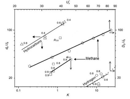
The limits of flame propagation and the onset of flame quenching are displayed in Figure 5. Regimes in which flame quenching and flame propagation occur are shown for both jet and premixed flames by the quench lines in the figure (Figure 5). Flame propagation is associated with increases in Ub* and Db/δk for jet flames, and in K and dk/δk for premixed flames. Here, dk is the optically measured extinction diameter of a flame kernel. For a particular fuel, a flame can only exist above its quench line. Below the line, it is extinguished. For the jet flames, an increase in Ub* at constant D/δk causes an increase in the ratio of chemical to eddy lifetime and eventual flame blow-off. A decrease in Db/δk, at constant Ub*, will also create extinction. For premixed flames, an increase in K and a decrease in dk/δk will cause eventual flame extinction.
The lowest quench line for hydrogen is unique for its high reactivity, for the reasons discussed earlier. The high hydrocarbons quench line characterises higher paraffins, up to i-octane, which is indicative of a relatively low reactivity. Methane is more reactive and, uniquely, has both jet and premixed plots that exhibit an interesting similarity. The lower, shorter, methane and line features flame quenching data from a swinging laser sheet. The more extensive upper data are from the jet flame blow-off data. The similarity of the two relationships supports the generality of this flame-quenching phenomenon. Despite earlier references to differences, the dissipation and quenching in Figure 5 draw attention to commonality.
The significant differences in performance between jet and premixed flames are largely due to their distinct combustion dynamics and flame stability characteristics. In the case of jet flames, the combustion process is localized to the reactive central zone, with the edges of the flame becoming progressively leaner, causing reduced reaction rates and potential extinction at the periphery. This localized combustion is limited by the amount of air that can be entrained by the jet at higher velocities. Conversely, premixed flames benefit from more uniform and thorough mixing of fuel and air before ignition, which enhances the overall efficiency and stability of the flame, leading to higher heat release rates and reduced susceptibility to quenching. The relationship between the turbulence parameters, such as K and dk/δk, plays a crucial role in determining the flame’s stability in premixed systems. For jet flames, the interplay between the blow-off velocity (Ub*) and flame quenching diameter (Db/δk) is critical in determining the conditions under which the flame will extinguish.
The ability of premixed flames to achieve a higher heat release rate, as demonstrated by the significant power increase (78.3 kW compared to 20.05 kW in jet flames), can be attributed to the greater control over combustion conditions that is achievable in such systems. Additionally, the similarity in the flame quenching behaviour of methane in both jet and premixed flames underscores the broader applicability of the quenching phenomena, providing stronger evidence for the consistency of the fundamental combustion principles across different flame types. The observed differences in flame structures and performance emphasize the need for targeted design considerations to optimize combustion efficiency and mitigate quenching risks.
6. Conclusions
The main conclusions are as follows:
- Jet flame atmospheric combustion, over a wide range of fuels, is well generalised in terms of a Flow number, U*, and the inverse of the fuel flow pipe diameter normalised by the flame thickness of the maximum laminar burning velocity of the fuel, δk/D.
- Blow-off velocities increase near-linearly with pipe diameter for a variety of fuels, and the generalised approach enables values of heat release rates at flame blow-off from a pipe of 3 mm diameter to be derived for ten fuels. These ranged from 1,460.1 kW for H2 down to 1.84 kW for a (0.2 H2-0.8 NH3) blend.
- Numerical analyses revealed the detailed fire plume structure of a 20.05 kW, 28 m/s jet velocity CH4 jet from a 0.005 m diameter pipe. The plume volume was 2,433∙10-3 m3 and the volumetric heat release rate 20.05 kW. Only 0.17 of the plume volumes supported combustion.
- At the leading edge of a fuel jet, the fuel/air proportions are close to stoichiometric, but along the edge of the jet, the proportion of air increases with radius, eventually falling outside the limit of flammability. Some air never mixes with fuel, whilst some mixes, but remains outside the limit of flammability. This, along with the radiative loss from the plume, will decrease the combustion efficiency.
- Premixed combustion is more controllable, with more variables. and is potentially more effective than fuel jet combustion. Conditions are identified in Figure 4 for optimising atmospheric stoichiometric premixed combustion in a burner.
- Simultaneous mixing and turbulising of the fuel-air mixture ahead of combustion are necessary for optimising the premixed burner performance.
- The premixed burner generates 78.3 kW, almost 4 times the power of the jet flame, which requires about 0.4 times as much generating volume.
- The premixture burner developed a power of 78.3 kW, whilst the jet flame developed a lower power of 20.05 kW.
- A Quench Diagram shows plots of Ub* and K, plotted on upper and lower x axes, against respective normalised quenching pipe and flame kernel diameters are on side y axes. Above the straight quench lines for different fuels on such a Quench Diagram, straight flames can propagate below them, but they quench.
- There are clear differences between fuels in their quenching properties. H2 is the most reactive, and the higher hydrocarbons are the least.
- The commonality in style of the plots for both types of flame is indicative of some commonality in underlying phenomena.
Acknowledgements
The authors acknowledge the Deanship of Scientific Research, Vice Presidency for Graduate Studies and Scientific Research at King Faisal University, Saudi Arabia, for financial support under the annual funding track [KFU250158].
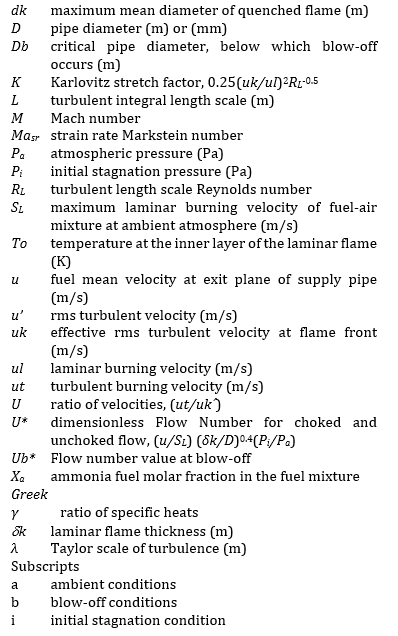
Nomenclature
References
[1] Z. Nannan, F. Tang, F. Xinyang, L. Jiang, Z. Xiaochun, Z. Xiaolong, L. Hu, "Effect of crosswind on the blowout limit of hydrogen-blended natural gas horizontal jet flame," Energy., vol. 317, pp. 134703, 2025. View Article
[2] A. Palacios, D. Bradley, L. Hu, "Blow-off of fuel jet flames in the atmosphere," Fire Saf. J., vol. 141, pp. 104007, 2023. View Article
[3] T. Keiji, S. Yamamoto, R. Sakatsume, S. Hirakawa, H. Takeda, V. Shentsov, D. Makarov, V. Molkov, "Effect of shock structure on stabilization and blow-off of hydrogen jet flames," Int. J. Hydrog. Energy. vol. 45, pp. 10145e10154 , 2020. View Article
[4] Y. Kang, Q. Wang, P. Zhang, C. Liu, X. Lu, Q. Wang, "Study on flame structure and extinction mechanism of dimethyl ether spherical diffusion flames," Energy, vol. 193, pp. 116786, 2020. View Article
[5] B. Rengel, A. Palacios, "Analysis of experimental blowout velocities of jet flames," Combust. Flame, vol. 213, pp. 237-239, 2020. View Article
[6] M.G. De Giorgi, A. Ficarella, A. Sciolti, E. Pescini, S. Campilongo, G. Di Lecce, "Improvement of lean flame stability of inverse methane/air diffusion flame by using coaxial dielectric plasma discharge actuators," Energy, vol. 126 pp. 689-706, 2017. View Article
[7] D. Bradley, P.H. Gaskell, Xiaojun Gu, "The mathematical modelling of liftoff and blowoff of turbulent non-premixed methane jet flames at high strain rates," Proc. Combust. Inst., vol. 27, pp. 1199-1206, 1998. View Article
[8] D. Bradley, P.H. Gaskell, Xiaojun Gu, A. Palacios, WJet flame heights, lift-off distances, and mean flame surface density for extensive ranges of fuels and flow rates," Combust. Flame., vol. 164, pp. 400-409, 2016. View Article
[9] A. Palacios, D. Bradley, "Generalised correlations of blow-off and flame quenching for sub-sonic and choked jet flames," Combust. Flame., vol. 185, pp. 309-318, 2017. View Article
[10] J. Göttgens, F. Mauss, N. Peters, "Analytic approximations of burning velocities and flame thicknesses of lean hydrogen, methane, ethylene, ethane, acetylene and propane flames," Proc. Combust. Inst., vol. 24, pp. 129-135, 1992. View Article
[11] G.T. Kalghatgi, "Lift-off heights and visible lengths of vertical turbulent jet diffusion flames in still air," Combust. Sci. Technol., vol. 41, pp. 17-29, 1984. View Article
[12] D. Stamps, S. Tieszen, "Blow out of turbulent jet diffusion flames," Fuel., vol. 118, pp. 113-122, 2014. View Article
[13] D.H. Um, J.M. Joo, S. Lee, O.C. Kwon, "Combustion stability limits and NOx emissions of non-prefixed ammonia-substituted hydrogen-air flames," Int. J. Hydrog. Energy., vol. 38, pp. 14854-14865, 2013. View Article
[14] C. Morley (2005). GasEq. A chemical equilibrium program for windows [Online]. Available: http://www.gaseq.co.uk. View Article
[15] A. Palacios, D. Bradley, "Hydrogen generation and its venting from nuclear reactors," Fire Saf. J., vol. 113, pp. 1-7, 2020. View Article
[16] D. Bradley, "How fast can we burn?," Proc. Combust. Inst., vol. 24, pp. 247-262, 1992. View Article
[17] Habib N. Najm, P.H. Paul, C.J. Mueller, P.S. "Wyckoff, On the adequacy of certain experimental observables as measurements of flame burning rate," Combust. Flame., vol. 113, pp. 312-332, 1998. View Article
[18] S. Hochgreb, "How fast can we burn? 2.0," Proc. Combust. Inst., vol. 39, pp. 1-29, 2022. View Article
[19] D. Bradley, M. Lawes. S. Mansour, "Correlation of turbulent burning velocities of ethanol-air, measured in a fan-stirred bomb up to 1.2 MPa," Combust. Flame., vol. 158, pp. 123-138, 2011. View Article
[20] D. Bradley, M. Lawes, Kexin Liu, M.S. Mansour, "Measurements and correlations of turbulent burning velocities over wide ranges of fuels and elevated pressures," Proc. Combust. Inst., vol. 34, pp. 1519-1526, 2013. View Article
[21] Xiaojun Gu, M.Z. Haq, M. Lawes, R. Woolley, "Laminar burning velocity and Markstein lengths of methane-air mixtures," Combust. Flame., vol. 121, pp. 41-58, 2000. View Article
[22] Jinhua Wang, Meng Zhang, Yongliang Xiea, Zuohua Huang, Taku Kudo, Hideaki Kobayashi. "Correlation of turbulent burning velocity for syngas/air mixtures at high pressure up to 1.0 MPa," Exp. Therm. Fluid Sci., vol. 50, pp. 90-96, 2013. View Article
[23] P.E. Roach, "The generation of nearly isotropic turbulence by means of grids," Int. Jour. Heat and Flow., vol. 8, pp. 82-92, 1987. View Article
[24] D. Bradley, M. Shehata, M. Lawes, P. Ahmed, "Flame extinctions: critical stretch rates and sizes," Combust. Flame., vol. 212, pp 459-468, 2020. View Article