Journal of Fluid Flow, Heat and Mass Transfer (JFFHMT)
ISSN: 2368-6111

Volume 12 - Year 2025 - Pages 128-138
DOI: 10.11159/jffhmt.2025.014
Simulation of Airflow and Heat Transfer in a Habitat with a Gable Roof Subjected To Directional Solar Irradiation
Kodjo Kpode1, Yawovi Nougbléga2, Hodo-abalo SAMAH1, Batanta Bataka1
1Laboratoire Matériaux, Energies Renouvelables et Environnement,, University of Kara, 400 Kara BP 404, Togo
k.kpode@univkara.net; samah.abalo@gmail.com; pbataka@yahoo.fr
2Regional Centre of Excellence on Electricity Management (CERME), University of Lomé, 01 Lomé BP 1515, Togo
nycogl@yahoo.fr
Abstract - Natural convection from roofs subjected to directional solar irradiation is numerically studied in a typical habitat. The roof consists of two slopes that do not receive the same amount of solar irradiation at any given time. The slopes would act as a thermal screen for each other, resulting in reduced heating through the roof. To achieve this, a cavity with a straight pentagonal cross-section is subjected to a heat flux model whose intensity on each slope depends on the apparent position of the sun relative to the roof. The numerical approach is based on the finite volume method. The resolution of the unsteady natural convection equations has enabled us to determine the heat transfer and air flow which are highly dependent on the apparent position of the sun and Rayleigh number. The east-west orientation and the apparent movement of the sun cause the right slope to receive solar irradiation first. It acts as a thermal screen for the opposite slope, which remains in the shadow until it reaches its peak solar irradiation. The average Nusselt numbers show that, overall, the heat exchange between the fluid and the slope that first received the solar irradiation remains high. Unlike many previous studies in which the slopes are subjected to the same heat flux profile (constant or variable over time), the flow exhibits no symmetry and is highly unstable, with the formation and disappearance of flow cells. The thermal field and system dynamics indicate that, for optimal ventilation driven by thermal buoyancy forces, it is essential to position the ventilation systems at the center of the slopes walls, especially the one that first receives the first solar radiation.
Keywords: Thermal screen, roof, solar radiation, natural convection, asymmetric flow, unstable flow.
© Copyright 2025 Authors - This is an Open Access article published under the Creative Commons Attribution License terms Creative Commons Attribution License terms. Unrestricted use, distribution, and reproduction in any medium are permitted, provided the original work is properly cited.
Date Received: 2025-02-17
Date Revised: 2025-03-13
Date Accepted: 2025-04-03
Date Published: 2025-04-15
1. Introduction
Above all, the roof is the envelope most exposed to solar radiation during a sunny day. In modern buildings, it is made from durable weather-resistant materials. However, these materials have high thermal effusivity and store a significant amount of heat, which is then transferred to the interior of the building. Nearly 32% of thermal discomfort is due to heat gain and/or loss through building envelopes [1]. The roof contributes almost 50% of the heat gained by a cabin [2].
To save on electrical energy (around 5.6 kWh/m² per month in London according to Song et al. [3]) required for active cooling – between 40-60% as reported by Lam et al. [4] and Omrany et al. [5] – and to limit the damaging consequences such as climate change and global warming, which are expected to reach a world record between July and August 2024 with a 1°C increase [6], it will be necessary to improve the thermal properties of building envelopes. To this end, several innovative passive technologies are being deployed. Some methods involve improving the albedo of building envelopes, particularly roofs [7]-[9]. Nano-coating of envelopes or the integration of reflective nanomaterials [10] into envelopes can reduce heat gain through these surfaces by more than 40% [11],[12]. During the day, the absorption of solar radiation by the envelope also depends on its color. For example, painting the roof a light color [13],[14] can reduce thermal gains by almost 30% compared to a roof painted in a dark color under the same conditions. The work of Alrwashdeh et al. [15] classifies white as the color that promotes heat loss, while black is seen as the color that enhances energy conservation.
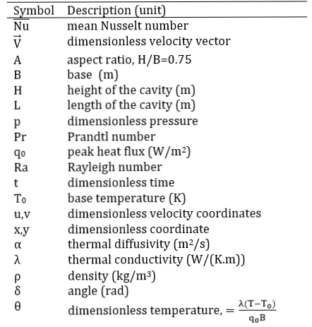
Nomenclature
Other technologies include green roofs, which involve covering building envelopes with green plants that grow and develop there. These green walls have the advantage of producing and regulating thermal airflow due to the plant’s ability to absorb carbon dioxide [16]. Through self-regulation, the green walls remain relatively warm in winter and relatively cool in summer. This thermal effect is estimated to range between 2°C and 2.63°C [17]. The thermal insulation effect of the envelopes is enhanced [18], and depending on the leaf area index, the loss or gain by convection [19],[20] is reduced because the wind speed is lowered.
However, while the known and quantified advantages of these technologies are enlightening in terms of building energy consumption and their environmental and economic benefits, they remain technologies that require significant financial resources in the short term and high maintenance costs, particularly in the case of green roofs and walls [21]. Mechanical wear or the aging of colors causes them to lose their reflectance quality. In countries with low incomes and low rainfall, where modern, energy-intensive buildings are on the rise, these technologies are either underdeveloped or non-existent. This is the common case of gable roofs made of metal roofing sheets in the sub-Saharan region. While the reflective surface of the metal sheets helps limit heat gain, this effectiveness could be further enhanced if the roof were properly oriented relative to the sun's rays.
It is therefore important to gain a better understanding, through this study, of heat exchange by natural convection in homes where the gable roof is exposed to heat flux that depends on the apparent movement of the sun. This will allow us to assess the role of the slopes as thermal screens for each other. Before, it is important to remember that natural convection in a closed cavity does not have the same characteristics as that in an open system, because the same volume of fluid is considered and it interacts with itself, making the boundary conditions omnipresent.
The fundamental aim of this study is to determine how the system evolves. The fact that the walls are subjected to constant or variable temperatures suggests that the system is evolving toward a quasi-stationary state [22] or oscillating periodically [23],[24]. However, by subjecting the inclined walls to sinusoidal temperatures, Saha et al. [24] numerically demonstrated that the flow is not stable. Since geometry affects the direction of transfer and modifies fluid dynamics [25],[26], this study also aims to identify the thermal buoyancy forces, whose direction depends on the orientation of the heat flux density.
From a practical point of view, the study aims to limit heat gain through the roof and avoid vertical temperature gradients, which are often the cause of thermal discomfort. To achieve this, it is advisable to consider the east-west orientation of the roof in relation to the sun's rays from the design stage.
2. Physical model and governing equation
2. 1. Geometry
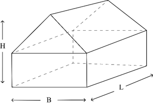
This study deals with the cavity with the right pentagonal section as shown in Figure 1a, b. The sloped walls are subjected to variable heat flux described in Figure 3. The vertical walls are thermally insulated, while the bottom wall is kept at the lowest isotherm T0. Then, we have the geometric configuration of an air-filled habitat.
 (a)
(a)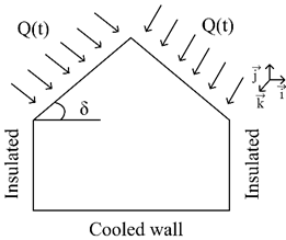 (b)
(b)2. 2. Heat flux
Empirical, experimental, and theoretical models [27]-[31] for assessing solar radiation flux density take into account many parameters such as the sun’s height, the incidence angle of direct and diffuse radiation, etc. However, as we are only interested in thermal effects, the mathematical formulation is intended to be very simple, but at best, it models the variation in heat flux intensity over time on an inclined plane. This variation, therefore, depends on the apparent east-west path of the sun. The assumptions used to calculate the variable density heat flux are as follows:
- the plane is inclined to the east-west horizontal direction,
- the sky is clear and not cloudy. The radiations are isotropic and direct. The diffuse radiations are neglected and there is no reflection on the planes,
- the sun is very far away and we have a beam of parallel rays,
- each plane is uniformly heated at a given time and the intensity varies with the direction of the beam relative to the normal to each plane,
- the first beam of incident rays arriving on the roof at the first instant t0 (sunrise) is horizontal. This direction changes over time and becomes vertical at the average time tm (zenith). Its direction becomes horizontal again at the final time tf, which corresponds to sunset,
- the walls subject to this heat flux are thermally thin.
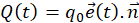
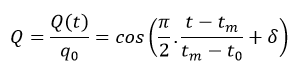
Taking into account all these assumptions, the useful flux in a direction normal ![]() to the walls is:
to the walls is:
Where:
q0 is the maximum value of the irradiation;
![]() is the unit vector of the incident flux direction.
The dimensionless heat flux is then calculated by :
is the unit vector of the incident flux direction.
The dimensionless heat flux is then calculated by :
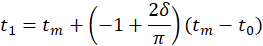
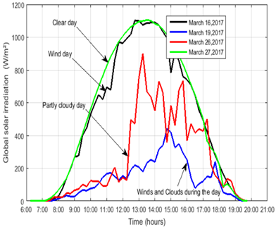
By choosing tf=2tm-t0, the dates t1 and t2 when the flux is zero on the west and east inclined wall, are respectively :
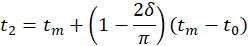
Thus, the radiation received by a horizontal plane (when δ=0 rad) exhibits a parabolic profile similar to the one predicted by Blal et al. [32] (Figure 2a, b). This model does not aim to evaluate the exact intensity of solar radiation but allows to approximate the amount of heat flux received over time by a plane due to the apparent east-west movement of the sun.
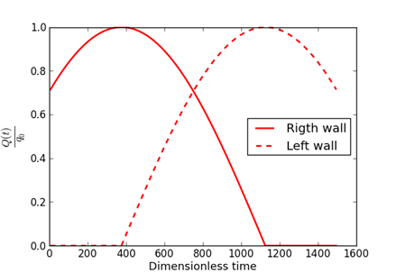
Therefore, the variations observed according to the east-west tilt of the surfaces (Figure 3.), show that the concept of directed flux or the thermal screen effect is taken into account in this study. The left inclined wall starts receiving solar radiation at t1=375, which corresponds to the peak flux received by the right inclined wall. At the median time tm=750, both walls receive the same amount of solar radiation. The peak for the left inclined wall is reached at t2= 1125 when the radiation on the right wall becomes zero.
 (a)
(a)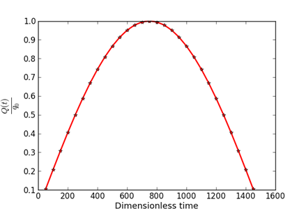 (b)
(b)Figure 2. Parabolic radiation in clear sky: predictive model of Blal et al. [32] (a) and our model (b)
 (a)
Figure 3. Heat flux applied on the inclined walls (δ=π/4 rad)
(a)
Figure 3. Heat flux applied on the inclined walls (δ=π/4 rad)
3. Methods
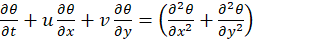
3.1. Governing equations
The fluid is air with a density ρ, thermal conductivity λ, and thermal diffusivity α. The equations governing the motion and the transfers are the simplified Navier-Stokes equations obtained under the Boussinesq assumptions and for an incompressible laminar flow. In terms of the dimensionless physical quantities
![]() and p, which represent the velocity, temperature, and pressure, respectively, they are written as follows in cartesian plane (x,y):
and p, which represent the velocity, temperature, and pressure, respectively, they are written as follows in cartesian plane (x,y):
- conservation of mass;

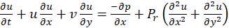
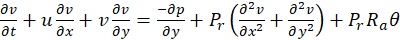
- conservation of momentum ;
- conservation of energy
The reference quantities used to obtain the above equations are B, B2/α, BQ/λ et ρα2/B2 , which represent the base length, velocity, temperature difference, and pressure, respectively. In the equations (6) and (7), the dimensionless numbers of Prandtl, Pr, and Rayleigh, Ra, appear. The initial and boundary conditions are translated as follows:
- at t=t0 :
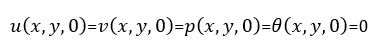
- at t>0:
- Hydrodynamic conditions on the walls
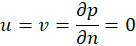
- Thermal conditions on the horizontal wall, vertical walls, and inclined walls are respectively:


The heat exchange between the walls and the air is represented by the local and mean Nusselt numbers, which are respectively defined as follows:

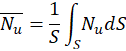
with θP and S the wall temperature and surface.
3.2. Numerical resolution
The finite volume method was used to numerically treat each of the governing equations. In their conservative form, they are written as:
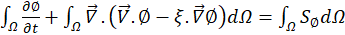
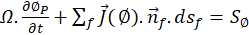
For a control volume Ω bounded by the surface S=∑f Sf, and centered at the node P, equation (16) is approximated by:
with :
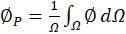

Where ∅, dΩ, ξ and S∅ are respectively the physical quantities (u,v,p,θ), a control volume element, the diffusion coefficient, and the source term of each equation. We summarize for each equation the quantity ∅, the diffusion coefficient ξ , and the source term S∅:
|
Equation |
∅ |
ξ |
S∅ |
|
mass |
1 |
0 |
0 |
|
momentum along x-axis |
u |
Pr | -∂p/∂x |
|
momentum along y-axis |
v | Pr |
-∂p/∂x+RaPrθ |
|
energy |
θ |
1 |
0 |
We used the power-law scheme of Patankar [33],[34] and an implicit decentred Euler scheme with a staggered mesh, to calculate the coefficients for each algebraic equation. Knowing the pressure field is essential for determining the velocity field. We decoupled velocity from pressure using the SIMPLER algorithm. The algebraic equations obtained for each quantity ∅ calculated at the node P, surrounded by the cardinal neighbors O, E, S, and N, are:
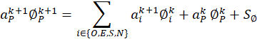
with k the time iteration index.
5. Results and discussions
For cases that are close to our study with cavities heated uniformly or not from above, the literature results fundamentally show that, overall, convective exchanges between the heated wall and the air in the cavity only begin when the Ra number is >106 [35]-[37]. Our calculations are therefore carried out in the Rayleigh Ra= 106-108 range, where the flow remains laminar [38]-[42].
5.1. Code validation
From one iteration to the next, the convergence criterion used at each step is:
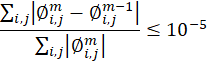
With i,j as the discrete indices for sweeping the domain along the x-axis and y-axis, respectively, and m, as the iteration index at a given time. The mesh with 181×141 nodes and a time step Δt =10-5 are used.
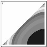
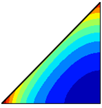
A reference case for the validation of our computational code is the work of Joudi et al [43], conducted under similar heating conditions in a triangular cross-section cavity. The computational code, developed in FORTRAN, is adapted to the model described above with the parabolic heat flux conditions. It is also tested under the working conditions of Flack [36], who measured natural convection in a triangular cavity heated from above. The comparisons of our results (see Figure 4 and Figure 5) with the findings of these authors show that our computation code is reliable
(a)
(b)
Figure 4. Temperature distribution during the winter day condition: Joudi et al. [43] (a) and present work (b)
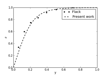 Figure 5. Temperature of the mid-plane [36]with Gr=2.84×10⁶.
5.2. Nusselt numbers
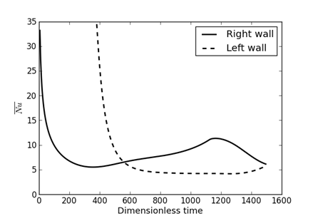
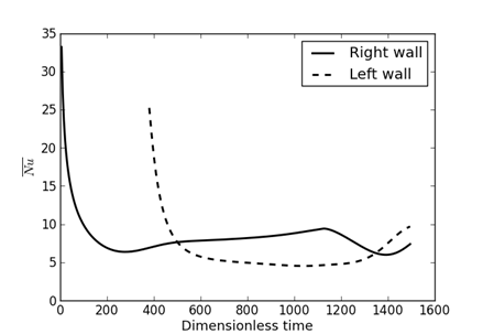
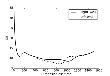
The curves in Figure 6 show the trend of heat exchanges between the inclined roof walls and the air. The thermal gains through the roof come only from the first inclined wall, which receives solar radiation until the moment t1 = 375 when the second inclined wall begins to receive it. For relatively low Rayleigh numbers, the heat input from the first wall receiving solar radiation (right inclined wall) remains high. One might expect an inversion with a much larger contribution from the left wall starting at the median time tm, but it will be necessary to wait for the peak of radiation received by this wall to be reached. This inversion is quickly observed as the Rayleigh number increases. It is also noted that not only do the transfer rates increase with the Rayleigh number, but also, after the left active wall receives the heat flux, the gap between the transfer rates between the two active walls and the fluid decreases, eventually tending toward zero (see Figure 6c).
 (a)
(a)
 (b)
(b)
 (c)
Figure 6. Mean Nusselt numbers calculated on actives walls : (a) Ra=5×10⁶; (b) Ra=107; (c) Ra=108
(c)
Figure 6. Mean Nusselt numbers calculated on actives walls : (a) Ra=5×10⁶; (b) Ra=107; (c) Ra=108
Furthermore, the first decrease of the curves corresponds to the state where transfers occur through weak convection. A single-cell flow is present. As convection develops, the sudden variations show the change of state with the birth of multicellular flows or a reorganization of the flow with the disappearance of cells.
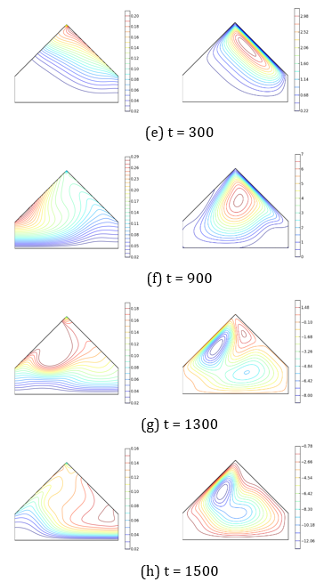
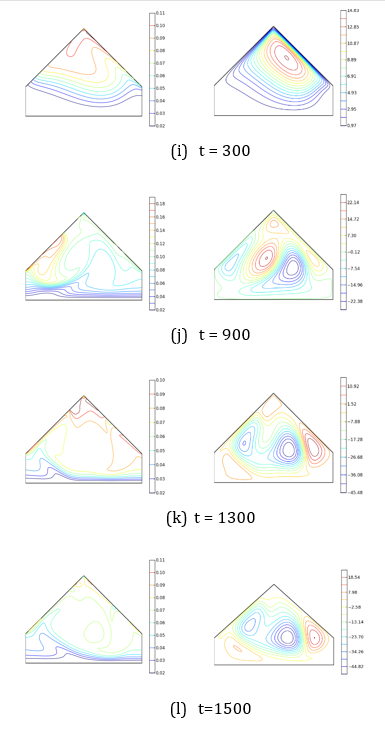
5.3. Streamlines and isotherms
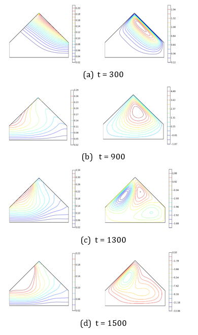
In Figure 7, the streamlines (on the right) and isotherms (on the left) are shown.
The streamlines represent the fluid flow within the domain. Thus, the movement is initiated by the fluid particles near the wall (on the right), which first receive the heat flux. Under the effect of buoyancy forces, they move along this wall and rise until they reach the left wall, from where, slightly cooled, they descend. Indeed, this wall not only acts as a barrier to the upward movement of the hot fluid but also as the place where it cools for moments t < t₁ = 375 (a time before the left wall does not receive irradiation). Thus, a main vortex is formed, extending along the active wall and rotating in counterclockwise. Its volume, which increases with time, shows the portion of the fluid in motion within the cavity (Figures 7a,b) for Ra = 5×10⁶, for example. However, the flow’s core remains at the same horizontal level in the triangular section and slowly migrates towards the mid-plane. High-intensity movements occur in the attic space. Unlike previous works [35],[37], where the flow exhibits a symmetry of two cells rotating in opposite directions, a single-cell flow is observed here. It becomes a multicellular flow more quickly as the Rayleigh number increases (see Figure 8f for Ra =107). Indeed, the main flow carries the relatively heavy fluid that rotates clockwise. The driven cell forms in the angle formed by the inclined and vertical right walls (see Figure 7f for Ra = 5×10⁶).
Additionally, near the left inclined wall, which increasingly receives the heat flux, thermal buoyancy forces are created, leading to the development of a counter-rotating convective cell. The main cell, thus trapped, disappears (see Figures 7c,d for Ra = 5×10⁶, for example) in favor of secondary cells. The system reorganizes, and the flow, with several cores, tends to become a monocellular counter-rotating flow, due to the relaxation of the right inclined wall (see Figures 8f-h for Ra=107). The multicellular nature of the flow appears after a relatively longer period when the Rayleigh number is low. Thus, the transition to a multicellular regime is observed at times t = 900 (see Figure 7b,c) and t = 300 (see Figures 9i,o), respectively for Rayleigh numbers Ra = 5×10⁶ and Ra = 10⁸.
The isotherms represent the temperature distribution within the domain. The nearly parallel shape of the isotherms at the first wall receiving the heat flux shows that, in the early moments t 300 (see Figures 7a and 8e), the transfers are dominated by conduction. Their deformation, with sudden depressions towards the left wall, indicates the expansion of the hot fluid due to recirculation movements. They are evenly spaced when conduction transfers remain predominant. The significant gaps that appear indicate that the regime is purely convective. Their tightening over longer times in the rectangular area shows that this zone is strongly stratified, due to the low fluid movement. These deformations also appear more quickly as the Rayleigh number increases.
6. Conclusion
Natural convection heat transfer in laminar flow is studied in a cavity with a straight pentagonal cross-section. This could represent a room, a warehouse, or a two-sided greenhouse. Due to its geographic orientation (east-west) and the apparent path of the sun, the two sides do not receive the same solar radiation. As a result, the sides act as thermal barriers for each other, reducing the thermal input from the roof. The contribution to the heating of the air in the habitat from the side that first receives the solar radiation remains high. Fundamentally, the uneven heating of the two sides leads to an asymmetrical and highly unstable flow. From a practical perspective, understanding these dynamics allows for better management of heat distribution and the prevention of cold or overly hot areas inside the building. This helps improve the design of natural or mechanical ventilation systems in buildings, optimizing the circulation of warm air to the areas where it is needed. Thus, it is preferable to create or place these ventilation systems (chimney, fan, etc.) in the center of the slopes, especially the one that first receives solar radiation.
References
[1] A. Nagaoka, Y. Ota, K.Sakai, K. Araki, H. Matsuo, N. Kadota, K. Nishioka, "Performance evaluation and spectrum-based analysis of a wall-mounted photovoltaic system for zero-energy building," Renewable energy, vol. 174, p. 147-156, 2021. View Article
[2] M. Rawat and R.N. Singh, "A study on the comparative review of cool roof thermal performance in various regions," Energy and Built Environment, vol. 3, p. 327-347, 2022. View Article
[3] J. Song, X. Huang, D. Shi, W. E.Lin, S. Fan, P. F. Linden, "Natural ventilation in London: Towards energy-efficient and healthy buildings," Building and Environment, vol. 195, p. 107722, 2021. View Article
[4] J. C. Lam, C. L. Tsang, D. H. Li, S. O. Cheung, "Residential building envelope heat gain and cooling energy requirements," Energy, vol. 30, p. 933-951, 2005. View Article
[5] H. Omrany, A. Ghaffarianhoseini, A. Ghaffarianhoseini, K. Raahemifar, J. Tookey, "Application of passive wall systems for improving the energy efficiency in buildings: A comprehensive review," Renewable and sustainable energy reviews, vol. 62, p. 1252-1269, 2016. View Article
[6] Copernicus, "Global Climate Highleights 2023," View Article
[7] M. Santamouris, "Cooling the cities-a review of reflective and green roof mitigation technologies to fight heat island and improve comfort in urban environments," Solar energy, vol. 103, p. 682-703, 2014. View Article
[8] Y. Qin, M. Zhang, J. E. Hiller, "Theoretical and experimental studies on the daily accumulative heat gain from cool roofs," Energy, vol. 129, p. 138-147, 2017. View Article
[9] J. A. Reagan and D. M. Acklam, "Solar reflectivity of common building materials and its influence on the roof heat gain of typical southwestern USA residences," Energy and Buildings, vol. 2, p. 237-248, 1979. View Article
[10] B. Ziaeemehr, Z. Jandaghian, H. Ge, M. Lacasse, T. Moore, "Increasing solar reflectivity of building envelope materials to mitigate urban heat islands: State-of-the-art review," Buildings, vol. 13, p. 2868, 2023. View Article
[11] J. Yuan, Z. Jiao, J. Chai, C. Farnham, K. Emura, "Reflective coatings: Enhancing building performance and sustainability," Nano-Structures & Nano-Objects, vol. 39, p. 101296, 2024. View Article
[12] R. C. Veloso, A. Souza, J. Maia, N. M. M. Ramos, J. Ventura, "Nanomaterials with high solar reflectance as an emerging path towards energy-efficient envelope systems: a review," Journal of Materials Science, vol. 56, p. 1-49, 2021. View Article
[13] H. Suehrcke, E. L. Peterson, N. Selby, "Effect of roof solar reflectance on the building heat gain in a hot climate," Energy and Buildings, vol. 40, p. 2224-2235, 2008. View Article
[14] M. A. William, M. J. Suárez‐López, S. Soutullo, A. A. Hanafy, "Building envelopes toward energy‐efficient buildings: A balanced multi‐approach decision making," International journal of energy research, vol. 45, p. 21096-21113, 2021. View Article
[15] S. S. Alrwashdeh, J. A. Qadourah, A. A. M. Al-Falahat, "Investigation of the effect of roof color on the energy use of a selected house in Amman, Jordan," Frontiers in Mechanical Engineering, vol. 8, p. 897170, 2022. View Article
[16] R. Sultana, Z. Ahmed, M. A. Hossain, B. A. Begum, "Impact of green roof on human comfort level and carbon sequestration: A microclimatic and comparative assessment in Dhaka City, Bangladesh," Urban Climate, vol. 38, p. 100878, 2021. View Article
[17] Y. Gao, E. Farrokhirad, A. Pitts, "The Impact of Orientation on Living Wall Façade Temperature: Manchester Case Study," Sustainability, vol. 15, p. 11109, 2023. View Article
[18] M. Solera Jimenez, "Green walls: a sustainable approach to climate change, a case study of London," Architectural Science Review, vol. 61, p. 48-57, 2018. View Article
[19] J. A. Palyvos, "A survey of wind convection coefficient correlations for building envelope energy systems' modeling," Applied thermal engineering, vol. 28, p. 801-808, 2008. View Article
[20] E. G. McPherson, L. P. Herrington, G. M. Heisler, "Impacts of vegetation on residential heating and cooling," Energy and Buildings, vol. 12, p. 41-51, 1988. View Article
[21] P. Rosasco, and K. Perini, "Evaluating the economic sustainability of a vertical greening system: A Cost-Benefit Analysis of a pilot project in mediterranean area," Building and Environment, vol. 142, p. 524-533, 2018. View Article
[22] S. C. Saha, "Unsteady natural convection in a triangular enclosure under isothermal heating," Energy and Buildings, vol. 43, p. 695-703, 2011. View Article
[23] Q. Xia, K. T. Yang, D. Mukutmoni, "Effect of imposed wall temperature oscillations on the stability of natural convection in a square enclosure," In Winter Annual Meeting of the American Society of Mechanical Engineers, vol. 117, p. 113-120, 1992. View Article
[24] S. C. Saha, J. C. Patterson, C. Lei, "Natural convection and heat transfer in attics subject to periodic thermal forcing," International Journal of Thermal Sciences, vol. 49, p. 1899-1910, 2010. View Article
[25] S. A. Rasheed and A. J. Hasan, "Effect of orientation on the natural convection heat transfer from a heated triangular prism embedded in porous media," Case Studies in Thermal Engineering, vol. 35, p. 102134, 2022. View Article
[26] Y S. Morsi, and D. Subrat, "Numerical investigation of natural convection inside complex enclosures," Heat transfer engineering, vol. 24, p. 30-41, 2003. View Article
[27] Z. Sen,"Solar energy fundamentals and modeling techniques: atmosphere, environment, climate change and renewable energy," Springer Science & Business Media, 2008.
[28] M. H. Soulouknga, O. Coulibaly, S. Y. Doka, T. C. Kofane, "Evaluation of global solar radiation from meteorological data in the Sahelian zone of Chad," Renewables: wind, water, and solar, vol. 4, p. 1-10, 2017. View Article
[29] K. Kerkouche, F. Cherfa, A. H. Arab, S. Bouchakour, K. Abdeladim, K. Bergheul, "Evaluation de l'irradiation solaire globale sur une surface inclinée selon différents modèles pour le site de Bouzaréah," Journal of Renewable Energies, vol. 16, p. 269-284, 2013. View Article
[30] C. Demain, M. Journée, C. Bertrand, "Evaluation of different models to estimate the global solar radiation on inclined surfaces," Renewable energy, vol. 50, p. 710-721, 2013. View Article
[31] S. A. Mousavi Maleki, H. Hizam, C. Gomes, "Estimation of hourly, daily and monthly global solar radiation on inclined surfaces: Models re-visited," Energies, vol. 10, p. 134, 2017. View Article
[32] M. Blal, S. Khelifi, R. Dabou, N. Sahouane, A. Slimani, A. Rouabhia, A. Ziane, A. Necaibia, A. Bouraiou, B. Tidjar, "A prediction models for estimating global solar radiation and evaluation meteorological effect on solar radiation potential under several weather conditions at the surface of Adrar environment," Measurement, vol. 152, p. 107348, 2020. View Article
[33] S. Patankar, "Numerical heat transfer and fluid flow," CRC press, 2018.
[34] H. K. Versteeg, "An introduction to computational fluid dynamics the finite volume method," 2/E. Pearson Education India, 2007.
[35] K. Kpode, M. L. Sow, C. Mbow, " Unsteady natural convection with summer boundary conditions in a habitat at high Rayleigh number and at high time," Energy and Buildings, vol. 121, p. 72-77, 2016. View Article
[36] R. D. Flack, "The experimental measurement of natural convection heat transfer in triangular enclosures heated or cooled from below," Heat Transfer, vol. 102, p. 770-772, 1980. View Article
[37] E. H. Ridouane, A. Campo, M. McGarry, " Numerical computation of buoyant airflows confined to attic spaces under opposing hot and cold wall conditions," International Journal of Thermal Sciences, vol. 44, p. 944-952, 2005. View Article
[38] W. Wu, and C. Y. Ching, "The effect of the top wall temperature on the laminar natural convection in rectangular cavities with different aspect ratios," J. Heat Transfer, vol. 131, p. 052501, 2009. View Article
[39] S. Paolucci and D. R. Chenoweth "Transition to chaos in a differentially heated vertical cavity," Journal of Fluid Mechanics, vol. 201, p. 379-410, 1989. View Article
[40] P. Le Quéré, "Accurate solutions to the square thermally driven cavity at high Rayleigh number," Computers & Fluids, vol. 20, p. 29-41, 1991. View Article
[41] P. Le Quéré and M. Behnia, " From onset of unsteadiness to chaos in a differentially heated square cavity," Journal of fluid mechanics, vol. 359, p.81107, 1998. View Article
[42] J. L. Lage, and A. Bejan, " The Ra-Pr domain of laminar natural convection in an enclosure heated from the side," Numerical heat transfer , vol. 19, p. 21-41, 1991. View Article
[43] K. A. Joudi, I. A. Hussein, A. A. Farhan, " Computational model for a prism shaped storage solar collector with a right triangular cross section," Energy Conversion and Management, vol. 45, p. 391-409, 2004. View Article