Journal of Fluid Flow, Heat and Mass Transfer (JFFHMT)
ISSN: 2368-6111

Volume 12 - Year 2025 - Pages 119-127
DOI: 10.11159/jffhmt.2025.013
Conversion of Waste Energy from CI Engines to Electrical Power with TEG
Jaafar Ali.Mahdi1, Hasanain J. A. Juaifer1,*, Hayder J. Kurji1, and Murtdha S. Imran1
1Kerbala University, College of Engineering, Mechanical Engineering Department
Farihah, Karbala, Karbala-56001, Iraq
hassanen.j@uokerbala.edu.iq
Abstract - All internal combustion engines exhibit significant energy loss during operation; the cooling and exhaust systems dissipate the bulk of the energy produced during combustion. The use of this energy enhances engine efficiency. One use of this capability is to enhance the efficiency of the engine's air intake, achieved using a turbocharger. Utilise thermoelectric generators (TEGs) to transform thermal energy into electrical energy. This investigation used a TEG model (27145) installed externally at the exhaust port. A system of four thermoelectric generators was established and interconnected in both series and parallel configurations. Measurements of current, voltage, power, and temperature fluctuations between the two sides of the thermoelectric generator were conducted using measuring devices.The practical component of the research was conducted at an ambient air temperature of 37°C, engine speed of 2340 rpm, specific fuel consumption of 0.173 kg/hr, and brake power of 2.34 kW. The empirical findings indicate that the maximum voltage and power achievable by connecting four thermoelectric generators in series are 13.33 volts and 11.25watts, respectively. Furthermore, when the thermoelectric generator was configured in parallel, the maximum current output was 3.14 amperes.
Keywords: CI engine, TEG, electrical power generation, waste heat.
© Copyright 2025 Authors - This is an Open Access article published under the Creative Commons Attribution License terms Creative Commons Attribution License terms. Unrestricted use, distribution, and reproduction in any medium are permitted, provided the original work is properly cited.
Date Received: 2025-03-21
Date Revised: 2025-03-30
Date Accepted: 2025-04-08
Date Published: 2025-04-11
1. Introduction
A difficulty for internal combustion engines is the energy loss that transpires during combustion. Approximately two-thirds of the energy is dissipated as heat, subsequently released into the environment by exhaust, engine cooling, or friction. Minimising fuel consumption and pollutant emissions necessitates the transformation of heat dissipated via exhaust gases and the engine's cooling process into electrical or mechanical energy [1]. Conventional methods used by engine professionals to attain their ambitious objectives include repurposing or using the turbocharger to effectively enhance air intake to the combustion chamber, hence optimising combustion. Power transformers, which convert thermal energy into electrical energy, are driven by the kinetic energy of exhaust gases. Thermoelectric generators are a modern method by which diesel and petrol engines reclaim wasted heat and convert it into electrical energy. Batteries may serve several functions after accumulating energy generated by the TEG [3]. Hybrid cars that focus on heat recovery integrate an electric motor with an ICE to reduce emissions from the combustion process of an additional internal combustion engine. Severe weather phenomena, including floods, heat-induced fires, and significant snowfall, are direct consequences of global climate change attributable to space pollution [4][5]. The economic aspect of using thermal generators lies in their ability to transform lost heat into electrical energy, which may be used in different components of the engine or to power an additional electric motor in hybrid vehicles. This indicates that we have decreased fuel use, hence reducing combustion emissions into the atmosphere. The primary objective of researchers in combustion engines and energy is to minimise fuel use and emissions. Lan et al. [6] use a three-way catalytic converter combined with an enhanced three-dimensional Multiphysics model of TEG to mimic its functionality. The central cavity of the hexagonal heat exchanger accumulates dissipate heat. The ideal location for the installation convertor is at the back, facilitating consistent heat distribution and an exceptional power output of 27.28 W, which exceeds the targeted system's power generation by 16%. Kim et al. [7] designed and fabricated WHR system, including sixteen modules of TEG connected with the power system, to evaluate the system's performance throughout several generation cycles. During the derivation cycles of the four vehicles, the pumping pressure is released on the low temperature surface of the cooling heat exchanger. The data indicate that electricity generation increases with the implementation of an integrated system. Nader [8] using TEG as an energy converter to examine the potential for fuel savings in hybrid electric vehicles (HEVs). The TEG saw a 7.7% decrease in fuel consumption. The ICE, responsible for more than 35% of combustion energy, generates significant heat. A study by Mohite et al. [9] investigated the influence of temperature on the transient energy generation (TEG) process at various engine speeds. Two TEG modules were placed on the top wall of an aluminium heat sink-equipped motorcycle engine silencer. The results showed a high-power recovery of 11.8 watts at 398°C hot face temperature and 9000 rpm engine speed. Zheng and Fan [10] examined the potential for fuel savings in conventional and hybrid electric vehicles using TEG as a secondary power source. The modelling results indicate that hybrid electric vehicles decreased fuel usage by 7.5% relative to conventional automobiles. Yu and Chau [11] performed a theoretical analysis of (TEG) system for vehicle exhaust, followed by practical study to ascertain the maximum power production. The experiment examined various hot-side temperatures and their correlation with power generation and load resistance. The results indicated that the load of internal resistance would increase in conjunction with the rising temperature of the hot face.
Liu et al. [12] designed a WHRS for engine car. During the evaluation, the system demonstrated efficiency results, leading to the conclusion that design optimisation was essential to rise the system's efficiency. Zhang et al. [13] constructed a nanostructured bulk material and fabricated a module. This thermoelectric generator has a density of power of 5.26 W/cm² and a temperature differential of 500 °C. Subsequent to the design and building of a WHRS including four hundred modules, the authors subjected the system to rigorous testing on a CI engine used in a vehicle. The highest power output that could be achieved at 550 °C on average and 480 g/sec for the mass flow rate of exhaust gas was 1002.6 watts. Kumar et al. [14] examined the impact of HE designs on the efficacy of WHRS. Their study identified the optimal design alternative via theoretical analysis using CFD software and a computer-aided design (CAD) application. Theoretical studies indicate that, in (WHRS) used in (SI) engine, the square shape is more efficient than other configurations for HT. Eighteen TEGs were used in the WHRS, connected in series to provide 25 watts of electricity. By harnessing dissipate heat, fuel consumption was minimised, and engine emissions were reduced. Kim et al. [15] performed experimental research on a TEG system to restor waste heat from a six-cylinder CI engine. A rectangular HE with dimensions of 25.35 cm × 37.2 cm × 6 cm was used to accommodate 40 specialised modules inside the system. An engine brake signifies an effective pressure between 0.2 and 1.0 MPa, used with a rotational speed of 1000 to 2000 RPM. The testing findings indicate that at a speed of engine 2000 RPM, the highest value of power output was 119 W, with conversion efficiency varying from 0.9% to 2.8%. In all testing conditions, the study revealed that power production improved with engine load or speed, but pressure reductions stayed lower 1.46 kPa.
R. Stobart et al. [16] examined the impact of HE designs on the operation of diesel and petrol engines inside WHRS. The researchers examined the impact of back pressure on the HE and the machine. The WHRS design included a total of 18 (TEGs). The testing results indicated that the augmented reverse pressure resulting from the WHRS design was minimal and had a minor effect on the engine's overall performance. Li et al. [17] investigated the impact of thermoelectric module distribution patterns and quantity on system performance. The engine is a diesel variant with a capacity of 11.12 litres. The system's components were derived from Bi2Te3. The results indicate that the ideal circumstances were an exhaust temperature of 805 K and a mass flow rate of 0.5 kg/s. A total of 217.35 W of electrical power was generated, exhibiting a change efficiency of 3.45%. In their study, Dai et al. [18] looked into the consequences of deploying an electromagnetic pump in (WHRS) with liquid metal as the working fluid. On the top wall of the silencer were mounted fourteen TEGs. With WH, an open circuit voltage of 34.7 V was produced.
Lan et al. [19] created a model for (WHR) in a heavy-duty truck using a (TEG) and counterflow heat exchangers (HEXs). The investigation determined that the generated TEG model could provide power between 170 and 220 W. The optimised parameters, namely the heat transfer coefficient and thermal contact conductance, mostly contributed to the power increase. The design of the engine silencer that captures WH was the distinguishing element of this research compared to others. The heat exchanger construction rapidly elevated the TEG's hot side to its maximum temperature. This study's comparison with prior experimental results indicates that the WHRS exhibits increased current, voltage, and power output. The chief objective of this project is to develop a method to capture the electrical energy produced by the engine's waste heat via alterations to the exhaust system.
2. The Principles of Operation of TEG
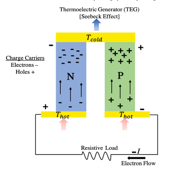
An example of a device that may convert thermal energy into electrical energy is the TEG, which can be shown in Figure 1. The operation of TEG is governed by the Seebeck effect. One of the most basic components of the thermoelectric generator's principles for the generation of electrical power is the p-n junction, which is constructed from a certain constituent material. Part P consists of holes, whereas part N contains electrons at the P-N junction [20]. The temperature gradient between the p-n junction and the surrounding material facilitates the movement of electrons and holes from the high temperature side to the low temperature side. This shift is enabled by solar or waste heat transferring to the cold side, dispersing it, while electrons and holes return to the hot side to reclaim heat energy [21]. By reclaiming the dissipated thermal energy, electrons and holes engage in a closed circular motion [22]. Upon an electron's interaction with a hole, an electrical circuit is established whereby the electron supplies electrical energy; this operational process is seen in Figure 2.
3. Experimental Part
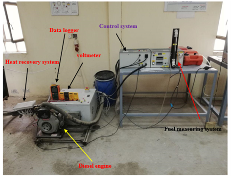
The experimental configuration included a single-cylinder CI engine, as seen in Figure 3. This engine had a naturally aspirated, air-cooled, four-stroke configuration. A dynamometer was used to quantify the engine brake power. The engine's load fluctuated with the variations in speed of dynamometers. The measuring of engine fuel consumption may be performed via a timer and a graduated cylinder. Attached to the dynamometer shaft was a speed sensor that measured the engine's velocity. A type K temperature sensor was inserted into the exhaust pipe in order to measure the temperature. The WHRS was fastened directly to the exhaust port of the engine in order to collect the hot exhaust gasses. The muffler's construction from cast iron ensures it will withstand the intense heat from the exhaust. A 300 mm length and a 5.5 cm square cross-section characterize the item. The type 27145 thermoelectric generator was mounted on the engine silencer scheme.

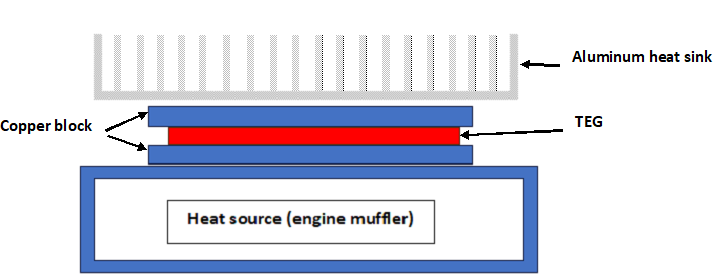
Within the TEG, there were two perforated copper slabs that served as heat sources and heat sinks, respectively. One slab was connected to the engine silencer and the other was to the aluminium fins.
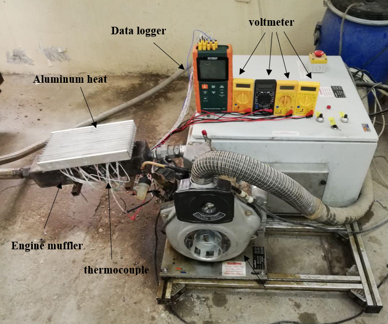
We tracked the cold and hot wall temperatures of the generator. The two copper slabs have perforations for the insertion of thermocouples, enabling accurate temperature measurement on both sides of the TEG. Thermal grease is used at the junction of the thermoelectric generator, two copper slabs, and the muffler surface to minimise thermal resistance at the interfacing surfaces of the WHRS. The TEG's low-temperature surface is cooled by an aluminium heat sink with 20 fins. Heat is transported from the upper surface of the aluminium heat sink by natural convection. The WHRS is seen in Fig. 4 and then illustrated schematically in figure 5.
3.1 Performance Calculation Equations for Engines
The following equation was used to determine the engine's performance [24][25]:
1- The rate of fuel mass flow,

2- brake

3- BSFC

4- Air consumption

5- Thermal efficiency of brake

3.2 Economic Evaluation
An economic evaluation of the four thermoelectric units is then performed to determine the system's financial feasibility, after the computation of their maximum power generation. Prior work in economic evaluation of thermoelectric systems has taken into account a variety of costs. This study aims to provide a more accurate cost estimate by combining different cost factors that have been gathered from the literature. There is typically no need to worry about operation and maintenance costs with TEG systems because, once installed, there is no need to do any kind of maintenance. This is how the TEG system's overall cost is calculated:

Where CB+CM,B+CM,A+CHE+CI represents the cost of the material, manufacturing, heat exchanger, and installation, in that order. The cost of one TEG model 27145, which includes all the expenditures in equation (6), is 8 USD. The cost of four TEG models is 32 USD.
3.3 Analysis of Uncertainty and Measurement Precision
To guarantee the reliability of experimental results, it is essential to assess the measuring equipment's uncertainty and the system's accuracy. Various causes may contribute to an escalation in uncertainty. These include faulty or malfunctioning equipment, the testing environment (static or dynamic), the testing strategy and plan, and the methodologies used to analyse or visualise the results. The total uncertainty is obtained by aggregating all the uncertainties related to the parameters under consideration. The total percentage of uncertainty may be calculated using the specified method [26].
Overall uncertainty= [ (0.1)2+ (0.1)2+ (0.3)2+ (0.2)2]0.5= 0.387
Table 1: The tools utilized, together with their accuracy and uncertainty
| Equipment | Measurement section/td> | Accuracy | uncertainty |
| K-type thermocouple | MTemperature of TEG | ±0.5 oC | 0.15 oC |
| BTM-4208SD data logger | Temperature recorder | (0.4%+0.5 oC) | 0.3 oC |
| Voltmeter | Voltage | ± 0.05 V | 0.1 V |
| Ammeter/td> | Current | ± 0.3 A | 0.2 A |
3.4 Methodology for the Experiment
Following the transition of the engine testing apparatus and instruments to standby mode, two copper shims were installed together with eight thermocouples. The engine's velocity, braking torque, and fuel consumption per 10 millilitres were documented. The footage was captured using a mobile camera and then analysed on a computer. Measurements of current, voltage, and temperature were recorded in the Excel sheet at many places to illustrate the correlation between the factors that directly influenced the TEG's power production. The experimental conditions were maintained at 37 °C with a relative humidity of 45%.
4. Results and discussion
The following outcomes occurred as a consequence of installing the thermoelectric generator to produce electrical energy from engine waste heat at the outside surface of the engine silencer.
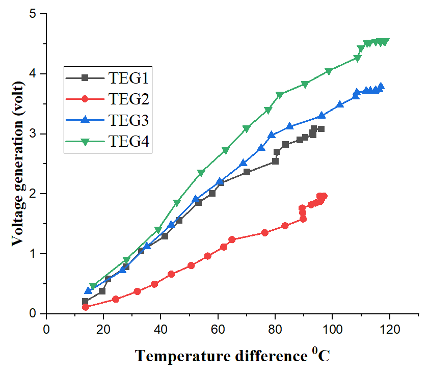
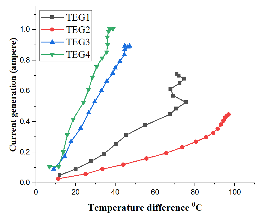
As the temperature of the hot portion rises, both the voltage production and the current generation increase. The greatest voltages generated by thermoelectric generators of TEG1, TEG2, TEG3, and TEG4 are 3.08,1.96,3.731 and 4.55 volts, respectively, as shown in Figure 6. The highest current generation values for TEG1, TEG2, TEG3, and TEG4 are 0.74,0.47,0.91 and 1.014 amperes, respectively, as shown in Figure 7. As the temperature on the hot face increases, the current and voltage on the other side also rise. The electrons and holes in the PN junctions are excited to migrate rapidly from the hot side to the cold side, forming an electrical series.
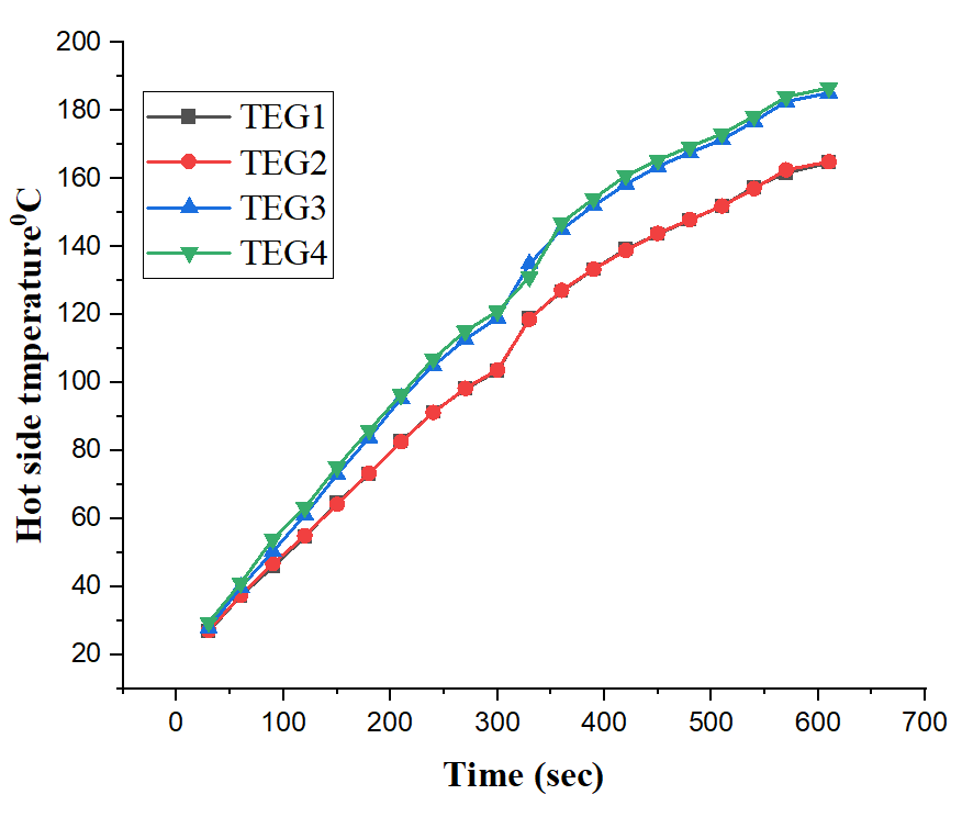
The current and voltage production progressively rise over time, as seen in Figure 8 and Figure 9. The voltage and current increase with time due to the corresponding rise in temperature on the hot side, as seen in Figure 10. The TEG1, TEG2, TEG3, and TEG4 saw maximum increases in hot face temperature of 177°C,181°C,203°C, and 205°C respectively.
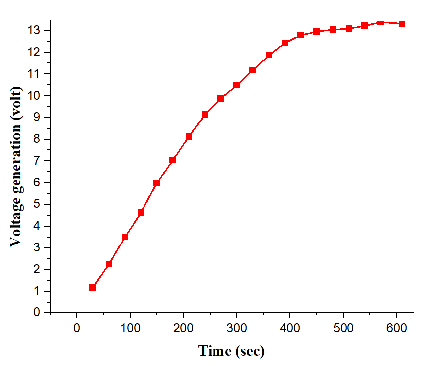
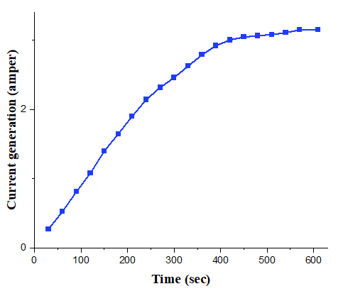
The overall voltage production increases with time when four TEGs are linked in series. The maximum voltage generation reaches 13.33 volts, as shown in Figure 11. Figure 12 shows that when the TEGs are connected in parallel, the total current output increases with time, reaching a maximum of 3.14 ampere.
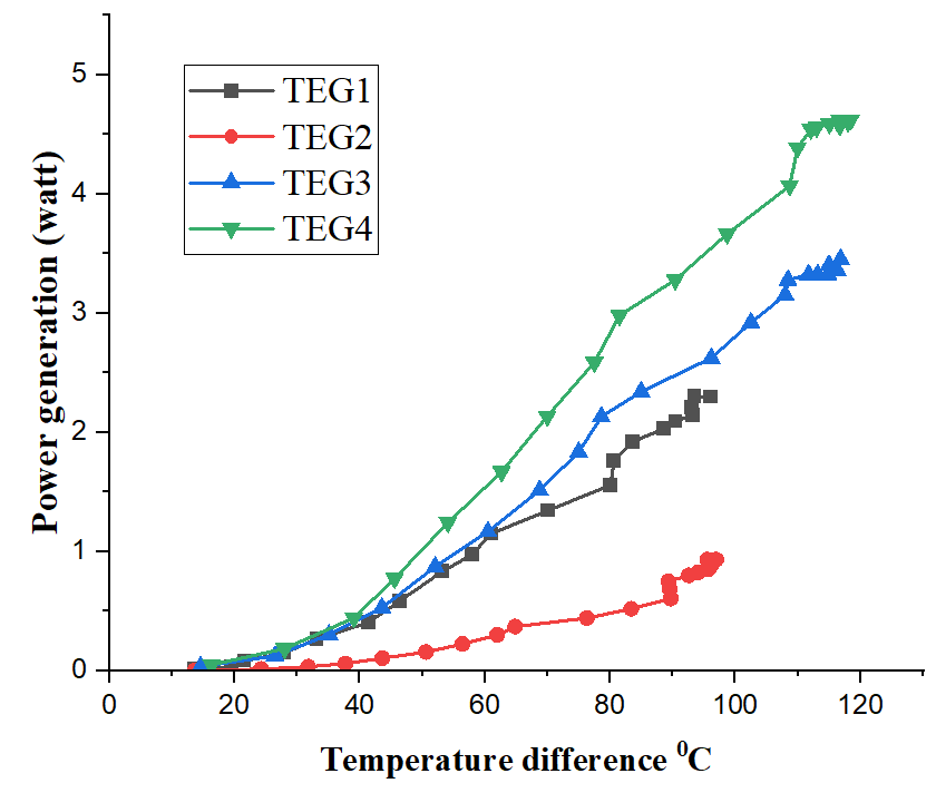
When the temperature change between the two faces of a single TEG grows, both the voltage produced and the current increase. As seen in Figure 13 and Figure 14. The TEG1, TEG2, TEG3, and TEG4 experience maximal temperature changes of 93.4°C, 96.9°C, 116.8°C, and 118.4°C, respectively. The acceleration of electron motion may be ascribed to the significant difference in temperature between the hot and cold faces, resulting in a rise in both voltage production and current. The TEG absorbs heat energy from the hot face and releases it later on the cold side. In this process, electrons return to the hot face to gather more heat. The reciprocal travel of electrons and holes results in their meeting, forming an electrical circuit generating electrical energy.
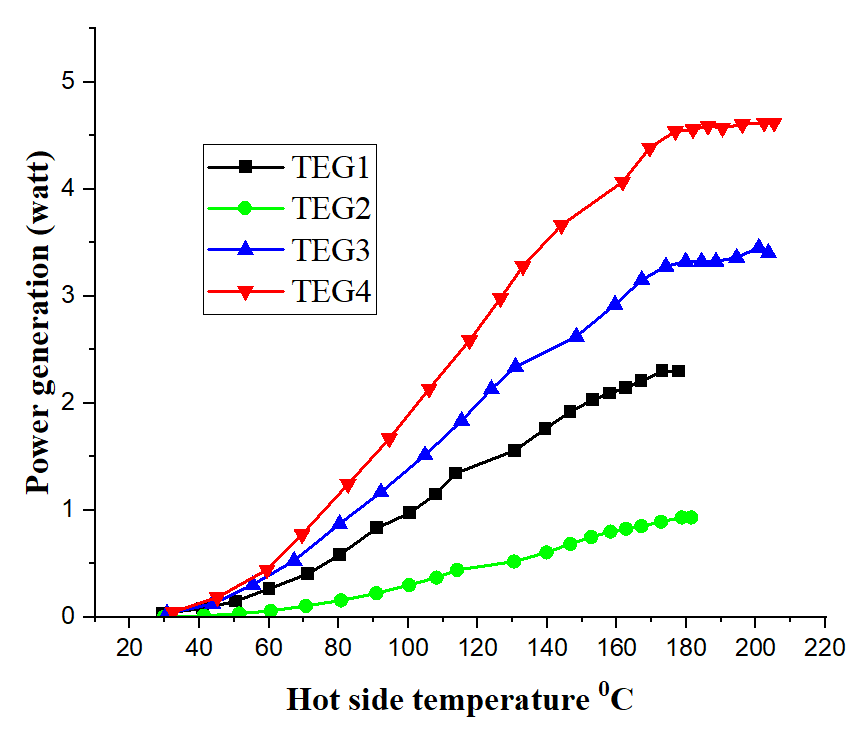
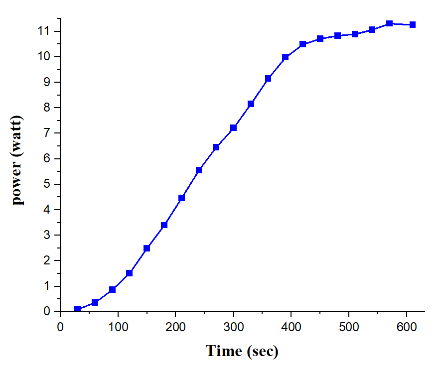
The power production experienced a rise due to an enhancement in the hot face temperature and temperature differential in each TEG, as shown in Figures 15 and 16. The TEG1, TEG2, TEG3, and TEG4 have maximum power-generating capacities of 2.29, 0.93,3.4 and 4.62 watts, respectively. Furthermore, the heat recovery system's overall power output progressively rose over time due to an elevation in the hot side temperature and temperature differential. The total power production reached a value of 11.25 watts. Figure 17 displays the correlation between overall power production and time. The growth in power production is directly related to the temperature difference, hot side temperature, and time. Specifically, power generation also increases when the temperature difference or hot face temperature rises over time. By accelerating the travel of electrons and holes in a PN junction, the rate at which electrons and holes encounter each other will increase. As a result, the power output from the WHRS will also increase.
5. Conclusion
Thermoelectric generators, part of waste heat recovery systems, generate electricity. The cooling process on the cold side by natural convection. The following are the conclusions drawn from the experimental data obtained during the practical stage of the research:
1. The temperature on the cold and hot sides rose with time. In thermoelectric generator number 4, the peak temperature that may be attained on the hot side is 205.26°C.
2. As the temperature of the hot face rised, the voltage, current, and power production all rose; the highest voltage generation was 13.33 volts, and the maximum current generation was 4.56 volts.
3. As the temperature differential and the amount of time pass, the voltage, current, and power production all show an upward trend. Up to 11.25watts of electricity may be generated.
Nomenclatures
| I | Electric current, A |
| LCV | Lower calorific value, kJ/kg |
| N | engine Speed, rpm |
| Tb | Torque of brake, N.m |
| V | Voltage, V |
| Vf | Volume of fuel consumption |
| Greek Symbols | |
| ΔP | pressure differences, kPa |
| ρf | Fuel Density, kg/m3 |
| Abbreviations | |
| Bi2Te3 | Bismuth Telluride. |
| CI | Compression ignition . |
| HE | Heat exchanger. |
| CE | Internal combustion engine |
| TEG | Thermoelectric generator |
| WHR | Heat Recovery of Waste |
References
1. IMRAN M. S., KURJI H. J. Waste heat conversion in compression ignition engine to the electric power by using exhaust heat recovery system contained TEG [J]. J. Mech. Eng. Res. Dev, 42(5), 101-105, 2019. View Article
2. IMRAN M. S., KURJI H. J., MAHDI J. A., ABDULSAHIB R. A. Exhaust waste energy harvesting by using a thermoelectric generator with a water heat exchanger. Journal of Engineering Science and Technology, 18(4), 2020-2034, 2023.
3. IMRAN M. S., HASHIM H. T. A heat recovery method of internal combustion engine using a thermoelectric generator. In IOP Conference Series: Materials Science and Engineering. IOP Publishing, 671(1), 12134, 2020. View Article
4. HASHIM H. T., IMRAN M. S. Electrical Current Generation Using SI Engine Waste Exhaust Heat in a Thermoelectric Generator. In IOP Conference Series: Materials Science and Engineering. IOP Publishing, 433(1), 12065, 2018. View Article
5. KASSIM M. S., IMRAN M. S., OBAID N. W. The influence of using palm oil and diesel fuel blends on compression ignition engine emissions and performance. In AIP Conference Proceedings. AIP Publishing, 2631(1), 2023. View Article
6. LAN S., YANG Z., CHEN R., STOBART R. A dynamic model for thermoelectric generator applied to vehicle waste heat recovery. Applied energy, 210, 327-338, 2018. View Article
7. KIM T. Y., KIM J. Assessment of the energy recovery potential of a thermoelectric generator system for passenger vehicles under various drive cycles. Energy, 143, 363-371, 2018. View Article
8. NADER W. B. Thermoelectric generator optimization for hybrid electric vehicles. Applied Thermal Engineering, 167, 114761,2020. View Article
9. MOHITE R. S., AYYUB K. O.,AHMED A. N. A. Thermoelectric heat recovery from four stroke engine. Int J Innov Res Creat Technol, 1, 511-515, 2015.
10. ZHENG S., FAN W. SIMULATIONS of TEG-Based Vehicle Power System's Impact on the Fuel Economy of Hybrid and Conventional Vehicles. SAE Technical Paper, 2016(1), 900,2016. View Article
11. ZHANG X., CHAU K. T., CHAN C. C. Design and implementation of a thermoelectric-photovoltaic hybrid energy source for hybrid electric vehicles. World Electric Vehicle Journal, 3(2), 271-281,2009. View Article
12. LIU X., DENG Y. D., CHEN S., WANG W. S., XU Y., SU C. Q. A case study on compatibility of automotive exhaust thermoelectric generation system, catalytic converter and muffler. Case Studies in Thermal Engineering, 2, 62-66, 2014. View Article
13. ZHANG Y., CLEARY M., WANG X., KEMPF N., SCHOENSEE L., YANG J., MEDA L. High-temperature and high-power-density nanostructured thermoelectric generator for automotive waste heat recovery. Energy Conversion and Management, 105, 946-950, 2015. View Article
14. KUMAR R. C., SONTHALIA A., GOEL R. Experimental study on waste heat recovery from an IC engine using thermoelectric technology. Thermal science, 15(4),1011-1022, 2011. View Article
15. KIM T. Y., NEGASH A. A., CHO G. Waste heat recovery of a diesel engine using a thermoelectric generator equipped with customized thermoelectric modules. Energy Conversion and Management, 124, 280-286, 2016. View Article
16. STOBART R. K., WIJEWARDANE A., ALLEN C. The potential for thermo-electric devices in passenger vehicle applications. SAE Technical Paper, 2010(1), 833, 2010. View Article
17. LI J. F., LIU W. S., ZHAO L. D., ZHAO M. High-performance nanostructured thermoelectric materials. NPG Asia Materials, 2(4), 152-158, 2010. View Article
18. DAI D., ZHAO Y., LIU J. Liquid metal based thermoelectric generation system for waste heat recovery. Renewable Energy, 36(12), 3530-3536, 2011. View Article
19. LAN S., YANG Z., CHEN R., STOBART R. A dynamic model for thermoelectric generator applied to vehicle waste heat recovery. Applied energy, 210, 327-338, 2018. View Article
20. NAKAMURA S., MORI Y., TAKARABE K. I. Mg2Si thermoelectric device fabrication with reused-silicon. In JJAP Conference Proceedings International Conference and Summer School on Advanced Silicide Technology. The Japan Society of Applied Physics, 2014, 011202-011202, 2015. View Article
21. TAKLA M., KJELSTRUP S., KOLBEINSEN L., KAMFJORD N. E. An investigation of the opportunity to recover radiation waste heat by the means of thermoelectricity, 2010.
22. MASTBERGEN D., WILLSON B., JOSHI S. Producing light from stoves using a thermoelectric generator. Ethos, 2005, 15-27, 2005.
23. JOUHARA H., ŻABNIENSKA-GORA A., KHORDEHGAH N., DORAGHI Q., AHMAD L., NORMAN L., DAI S. Thermoelectric generator (TEG) technologies and applications. International Journal of Thermofluids, 9, 100063, 2021. View Article
24. IMRAN M. S., KURJI H. J. The impact of using biodiesel prepared from waste sunflower oil & iraqi conventional diesel on compression ignition engine performance and emissions. Journal of Mechanical Engineering Research & Developments (JMERD), 41(3), 32-37, 2018. View Article
25. KURJI H., IMRAN M. S., IMRAN A. M. Experimental Comparison Between the Impact of using Two Types of Bio Diesel on Compression Ignition Engine Performance and Emissions. In IOP Conference Series: Materials Science and Engineering. IOP Publishing, 454 (1), 012034, 2018. View Article
26. IMRAN M. S., SALEH F. A. The influence of using biodiesel prepared from Cresson oil on emissions and performance of CI engines. Journal of Ecological Engineering, 25(1), 84-98, 2024. View Article