Journal of Fluid Flow, Heat and Mass Transfer (JFFHMT)
ISSN: 2368-6111

Volume 12 - Year 2025 - Pages 95-104
DOI: 10.11159/jffhmt.2025.010
Design and Numerical Evaluation of a Split-and-Recombined ‘(Y-H)αβ’ Micromixer
Md Readul Mahmud, Asma Begum, Farhad Alam
Independent University, Bangladesh, Department of Physical Sciences
Plot 16 Block B, Aftabuddin Ahmed Road Bashundhara R/A, Dhaka-1245, Bangladesh
mahmud.readul@iub.edu.bd; ablipi@iub.edu.bd; farhad@iub.edu.bd
Abstract - A novel split-and-recombined (SAR) micromixer namely ‘(Y-H)αβ’ composed with a ‘Y’ and a ‘H’ shaped mixing unit is proposed. The proposed ‘(Y-H)αβ’ micromixer is composed of four identical elements that are connected by angles α and β. The value of alpha (α) is varied from 0° to 90° to analyze the effect on mixing performance. Numerical analysis of fluid flow and mixing performance is conducted for miscible fluids, using Fluent 15 software for Reynolds numbers from 0.1 to 100. A well-known SAR mixer called ‘H-C’ is also analyzed for comparison. The numerical data shows that connecting angle α has a strong effect on the SAR process; the efficiency increases from 65% to 98% when alpha (α) changes from 0° to 45° at Re=100. The ‘(Y-H)αβ’ mixer shows notably lower pressure drop than the ‘H-C’ mixer irrespective of the value of connecting angle α and Reynolds numbers. The proposed mixer has a significantly lower Mixing Energy Cost (MEC) compared to the ‘(H-C)’ mixer.
Keywords: CFD, Micromixer, Mixing Energy Cost (MEC), Pressure drop, SAR.
© Copyright 2025 Authors - This is an Open Access article published under the Creative Commons Attribution License terms Creative Commons Attribution License terms. Unrestricted use, distribution, and reproduction in any medium are permitted, provided the original work is properly cited.
Date Received: 2025-01-22
Date Revised: 2025-03-03
Date Accepted: 2025-03-15
Date Published: 2025-03-24
1. Introduction
Applications for microfluidic systems are numerous including environmental science, chemical processes, biochemistry, biological interactions, drug delivery, medical diagnosis, chemical synthesis, the food industry, and many more [1]-[3]. Numerous benefits of microfluidic devices include quick analysis, mobility, increased control, low cost, quick throughput, and the use of fewer costly chemicals [4], [5]. High surface area to volume ratios and quick mass and heat transfer are two more special qualities of microfluidics that have opened the door for advancements in many scientific and industrial domains; and promise greater effectiveness, portability, and affordability in a broad range of applications [6]. Because of their small size, high-pressure requirements, and material sensitivity, flow fluid in micromixers frequently occurs under laminar conditions at low Reynolds numbers.
Molecular diffusion regulates the mixing in microchannels, and effective mixing requires a lengthy channel length and a relatively long time [7]. Inefficient mixing results at low Reynolds numbers caused by the microscale dimensions and low flow velocity inside micromixers. It is imperative to develop new technology capable of overcoming these innate challenges. Highly effective micromixers are essential to the microfluidic industry's rapid growth [8], [9]. Although diverse efforts have been employed to tackle these challenges, there is potential to develop novel mechanisms to achieve truly efficient mixing which is sustainable and cost-effective.
Numerous aspects of fluid flow, including pressure drop, velocity, vorticity, efficiency, and species concentration, can be analyzed thanks to computational fluid dynamics (CFD) [10]. The mixing process and associated flow patterns, such as streamlines, vortex formation, and velocity vectors, can also be seen with the use of CFD. As a result, many researchers have used CFD to analyze micromixers [11]-[14]. CFD has developed into an efficient, economical, and time-saving method for examining flow patterns and investigating novel microreactor geometries by visualizing the mixing and reaction process [15].
Micromixers are classified into two types: active and passive [16]. To achieve good mixing homogeneity of fluids, active micromixers depend on external energy sources such as electric field, pressure field, thermal field, magnetic field, and acoustic field or pulsating low to perturb the fluid flow [17], [18]. As a result, they have a highly accurate external control facility. Despite these benefits, active micromixers are expensive and difficult to fabricate and integrate due to their complicated architecture [19]. Conversely, passive micromixers rely on modifications to the channel shape and geometry to vary the liquid direction, break up the stratified flow, and accomplish effective mixing without additional energy sources. Additionally, passive mixers are inexpensive, quick to implement, and have straightforward architecture [8]. Due to their extremely low velocity, passive micromixers rely mostly on molecular diffusion for their mixing performance. However, altering the channel's structure and geometry might increase the amount of mixing, which will subsequently cause a chaotic advection of fluid [5].
Passive micromixers employ a variety of structures, including obstacle-based, chamber-based, meander-based, multiplanar structures [19], [20]; twisting channel walls [21]; staggered herringbone [22]; blocks or barriers in channels [23], [24]; surface grooves and baffles [25]; modified Tesla structure [26], [27]; and mixing unit stacking [28], [29] to improve mixing time and efficiency. By periodically separating and recombining fluids, SAR creates various fluid multi-laminations that significantly increase the interfacial area and mixing index. J. Branebjerg et al. [30] presented a 3D multiplanar passive micromixer operated at Reynolds values below 1. This micromixer's total mixing time was between 100 and 300 ms. X. Feng et al. [31] employed a 3D SAR-based micromixer in a different investigation, utilizing a self-rotating interface to improve mixing efficiency. Two 10.25 mm-long micromixers were created, and they were frequently stacked in X-H and X-O configurations. There was a maximum mixing efficiency of 91.8% and 89.4% with Reynolds numbers ranging from 0.3 to 60.
A new SAR mixer that is compatible with the polydimethylsiloxane (PDMS) microfabrication technique was built by S. W. Lee et al. [32] and D. S. Kim et al. [33] present the barrier-embedded Kenics micromixer (BEKM), a novel passive chaotic micromixer. Compared to T-pipe and Kenics mixers, the suggested mixer is more efficient. V. Viktorov et al. [33] propose and analyze three distinct designs of SAR mixers with Reynolds values ranging from 1 to 100. These mixers have a low-pressure drop and good efficiency. However, no information regarding mixing costs is given. Using a sequence of "OH"-shaped segments, S. Hossain et al. [35] created a passive micromixer based on the idea of a 3D serpentine SAR microchannel. The E-shaped and F-shaped SAR micromixers were proposed by X. Chen et al. [36], [37]. As demonstrated by the data, the mixing index can achieve 94% and 90%, respectively.
In this study, a split-and-recombined micromixer designated as ‘(Y-H)αβ’ and consisting of four components was introduced. The simulation examined how the connecting angle ‘α’ between the two elements influences the micromixer's mixing performance, within the Reynolds number range of 0.1 to 100, utilizing ANSYS 15 software to investigate the fluid flow patterns and mixing mechanisms. Previously published results on the ‘(H-C)’ mixer were also analyzed for comparative purposes. The effectiveness of the proposed micromixers was evaluated by calculating the Mixing Index (MI), Mixing Energy Cost (MEC), and the corresponding pressure drop.
2. Micromixer Design
A novel 3D split-and-recombined ‘(Y-H)αβ’ mixer is introduced, which consists of four identical components, each featuring one part shaped like a ‘Y’ and another shaped like an ‘H’, as illustrated in Figure 1. Each component measures 4 mm in length, while the height of the mixer remains consistently at 0.4 mm. The mixer is designed with two inlets: Input A and Input B, along with a single outlet. The input ports have a radius of 0.4 mm, whereas the outlet has a radius of 0.6 mm.
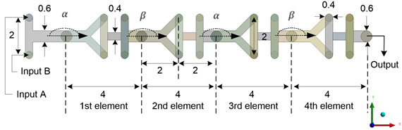
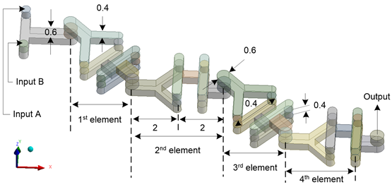
The four elements of the proposed ‘(Y-H)αβ’ mixer is connected through angles α and β. Angle α varies from 0° to 90°, increasing by 45° with each step, while angle β remains fixed at 0°. Consequently, three ‘(Y-H)αβ’ mixers are characterized by (Y-H)0° (α=0°), (Y-H)45° (α=45°), and (Y-H)90°(α=90°). Figure 2 illustrates (Y-H)45° (α=45°) along with key dimensions as an example.
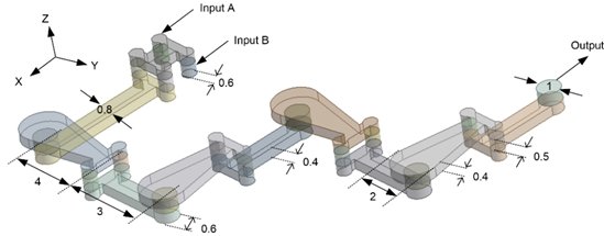
A published SAR mixer named ‘H-C’ [38] has been designed and analyzed through numerical methods to validate the numerical simulation method and establish a reference point for comparison. The ‘H-C’ mixer comprises four elements, each measuring 7 mm in length. Figure 3 illustrates the geometric configuration of the ‘H-C’ mixer along with its key dimensions.
3. Numerical Method
In this research, the micromixer's mixing efficiency and pressure drop are initially examined through numerical simulations with ANSYS Fluent 15. The foundational equations consist of the 3D Navier–Stokes equations, the continuity equation, and a species convection-diffusion equation. Given that the flow remains laminar, the subsequent equations are given below [39].


Where fluid velocity, density, dynamic viscosity, and pressure are represented by V, ρ, μ, and P, respectively. Additionally, C and D stand for the species' mass concentration and the fluids' coefficient of diffusion, respectively.
In microscale flow, the Reynolds number is a significant dimensionless parameter defined as follows [40]:

Where d is the characteristic length of the mixer channel. To quantify mixing performance, the following equations were employed [41]:
In equation (5) the mass fraction of cell i and the optimal mass fraction are represented by Ci, and Cm, respectively. In addition, σ and MI are the standard deviations of the mass fraction, and mixing index, respectively. Completed mixing is obtained when MI=1 and no mixing is expressed by MI equal to zero.
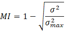
It is not enough to conduct a thorough analysis of both the mixing index and the corresponding pressure drop. In this regard, the notion of "mixing cost" is introduced to enable a comprehensive assessment of mixing performance, considering the energy needed to maintain flow in wavy micromixers with varying geometric characteristics and flow parameters. The mixing energy cost (MEC) is defined mathematically as the ratio of the input power to the mixing index and is a crucial factor for this research; mixing energy cost can be represented as [42]:
Where, “input power” refers to the energy required to sustain the fluid flow (Q), whereas the “mixing index” measures the extent of mixing accomplished in the micromixer. This ratio serves as an important criterion for evaluating the effectiveness of the mixing process to the energy input [43].
The "laminar flow" and "Species Transport" modules of Fluent are used to solve the equations in line with the finite element method. The fluids under analysis are an aqueous solution with a density of 1×10³ kg/m3 and a dynamic viscosity of 1× 10⁻³ Pa . There are two inlets on the micromixer, A and B. At the two inlets, the sample's mass concentrations are set to 0 and 1, respectively. The fluid dynamic boundary conditions are defined as no-slip, and the diffusion coefficient is set at 1×1-9 m2/s [44]. A second-order upwind approach is used to minimize numerical diffusion, and the SIMPLEC algorithm is used for pressure-velocity coupling [41]. To guarantee the utmost accuracy of the numerical solutions, the governing equations were solved through an iterative process, with a convergence criterion established at 1×10⁻⁶ for all values.
4. Mesh Independence Study
The commercial program ANSYS version 15 was used to do the CFD simulations and Fluent was chosen to precisely simulate the fluid dynamics in our micromixer design. Every microchannel needs to undergo a grid-independent test to guarantee accurate and consistent numerical simulation results.
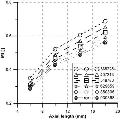
In this computation, six structured grid systems with grid numbers ranging from 234541 to 930368 were calculated for the (Y-H)0° (α=0°) mixer and tested at Re=10. Figure 4 displays the micromixers' mixing index (MI) profiles along the axial length channel. It is evident that the distance between the mixing index curves continuously narrows as the number of grids and channel length grows. Additionally, data with a maximum deviation of 2.8% MI are provided by two grids with 850896 and 930368 components. To save simulation time and expense, the grid of 850896 elements is selected for related simulations. For mixers (Y-H)45° (α=45°), and (Y-H)90° (α=90°), the same process is followed; the grid with 866416 nodes and 822344 nodes, respectively, is chosen for the simulations.
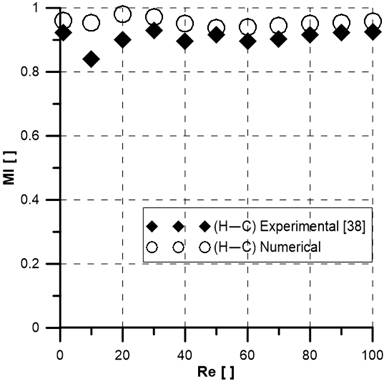
Now, to validate the simulation model the published experimental results [38] of the ‘H-C’ mixer are compared with simulation data obtained in this study. The comparison of the results of a three-dimensional ‘H-C’ SAR micromixer for a broad range of Reynolds numbers (1≤Re≤100) at Re=10 is illustrated in Figure 5. The experimental and numerical mixing index (MI) shows good agreement; the difference is less than 12%, which permits the current numerical approach to be used for additional study.
5. Result and Discussion
The current study used numerical simulation on '(Y-H)αβ' micromixers to examine how connecting angle α affects fluid mixing and how it affects fluid flow dynamics inside the mixing channel across a range of Reynolds numbers from 0.1 to 100.
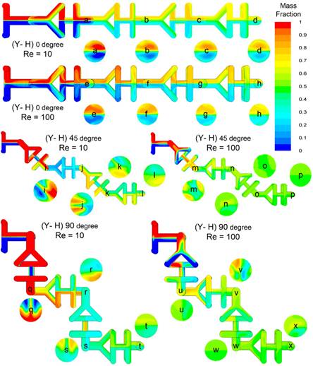
Firstly, the mass fraction distribution of fluids in a '(Y-H)αβ' micromixer for Re=10 and Re=100 is demonstrated in Figure 6. Red and blue colors represent two input fluids and contours express the mixing index where green color (Mass fraction = 0.50) indicates completer mixing. The liquid gradually splits into several smaller layers as the flow continues inside the channels for all mixers. Thus, the inter-liquid interface area is enlarged, and the performance of the mixture is improved. Mass fraction profiles were observed to be developed as Re changes from 10 to 100 for both (Y-H)45° and (Y-H)90° mixers but there is no noticeable change for (Y-H)0°. Figure 6 also clearly illustrates that the homogeneity of fluids at the output is greater at Re=100 than Re=10. Hence it is expected MI will increase for higher Reynolds numbers. It is also evident that MI will be dependent on angle α.
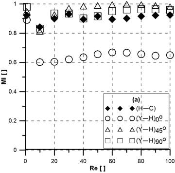
Now the mixing index with the Reynolds numbers for changing the angle α is studied. The mixing index of a known ‘(H-C)’ mixer is also added for comparison. The comparison of the mixing index and pressure drop with the Reynolds numbers is shown in Figure 7. All mixers show good efficiency at low velocity (Re=1) because the mixing time is large enough to mix the liquids. In Figure 7(a), (Y-H)45° mixer demonstrates the best MI performance of about 98% at Reynolds numbers ranging from 40 to 100. Among all presented mixers, (Y-H)0° presents a poor mixing index (about 65%) at Re ≥10. Meanwhile, (Y-H)90° and (H-C) show no noticeable difference of MI for Reynolds numbers for Re >50. However, the required pressure drop shows negligible dependence on a variation of connecting angle α, as demonstrated in Figure 7(b). However, the required pressure drop shows negligible dependence on the variation of connecting angle α, as demonstrated in Figure 7(b). The (H-C) mixer shows a significantly higher pressure drop compared to '(Y-H)αβ' mixers due to its longer channel length which is 38 mm. Whereas the length of '(Y-H)αβ' mixers are 18 mm only but the channel dimension is smaller (width: 4 mm, height: 4 mm & input diameter: 4 mm) in contrast to (H-C) mixer (width: 8 mm, height: 4 mm & input diameter: 6 mm); as a result the pressure drop of '(Y-H)αβ' mixers are not twice lower than (H-C) mixer.
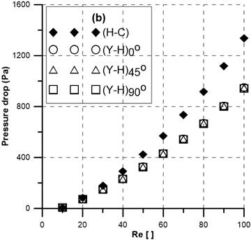
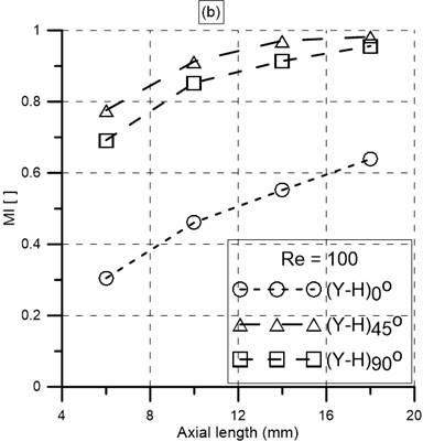
The dependency of the mixing index (MI) with the axial length is analyzed and shown in Figure 8. As expected the MI increases with the increase of axial length. The (Y-H)0° mixer shows the lowest performance irrespective of Reynolds numbers. Both (Y-H)45° and (Y-H)90° mixers show almost 82% and 92% MI at Re=10 and Re=100, respectively at the output. Therefore, MI can be increased by adding elements if required.
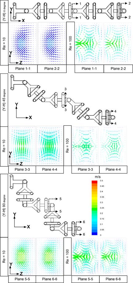
Figure 9 depicts the secondary flows after the 2nd and 4th elements within the middle of the YZ plane of the proposed mixers at different Reynolds numbers. At Reynolds numbers equal to 10, all mixers behave uniformly with weakly producing secondary flow. It is clear that the (Y-H)0° mixer has a significantly lower secondary flow which justifies the low MI (60%) as shown in Figure 7(a). On the other hand, at higher Reynolds numbers, Re=100, there is a significant change in velocity trent. The influence of secondary flow increases which in turn influences the contact surface, and as a result MI exhibits a high value (98%) for the (Y-H)45° and (Y-H)90° mixers. This finding confirms the conclusion drawn from Figure 7 and demonstrates the impact of the connecting angle α and its velocity at high Reynolds numbers.
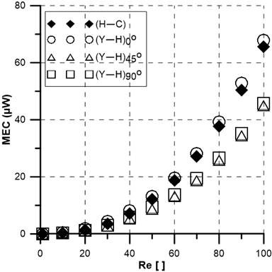
To have a comprehensive understanding of mixing performance it is important to consider the mixing energy cost (MEC). The MEC is calculated by taking into account variables like mixing index, pressure drop, and flow rate. The MEC of four SAR mixers is represented in Figure 10. The (H-C) and (Y-H)0° mixers have the highest MEC due to high-pressure drop and low MI, respectively. Interestingly both (Y-H)45° and (Y-H)90° has a lower MEC and has the same MEC. Although the (H-C) mixer has a slightly higher mixing index (MI) compared to the (Y-H)90°; the (Y-H)90° mixer shows the lowest mixing energy cost (MEC).
6. Conclusion
The effectiveness of mixing miscible fluids for a broad range of Reynolds numbers was investigated numerically by employing a new SAR '(Y-H)αβ' mixer with ‘Y’ and ‘H’ shaped mixing units. The four identical components that make up the mixer are joined one after the other by angles α and β. Ansys FLUENT 15, a commercial software program, was used to conduct the numerical analysis utilizing Navier Stoke and continuity equations for three mixers, represented as (Y-H)0°, (Y-H)45° and (Y-H)90°. The impact of the mixers' construction parameter (connecting angle α) on secondary flow pattern, pressure drop, mixing energy cost (MEC), and mixing efficiency (Mixing Index = MI). Numerical data clearly shows that the SAR process is greatly dependent on angle α; the highest effect is shown at α=45°, while the weakest effect is observed at α=0°. The mixing index is significantly greater when the value of connection angles α is not zero. The reason is that in comparison to all other values of angle α, the strength of secondary flow and multi-lamination is significantly lower at this angle. At Reynolds numbers ranging from 20 to 100, the mixing index for (Y-H)45° is greater than 95%. In order to validate the numerical model, a known SAR ‘H-C’ mixer is also investigated. The proposed '(Y-H)αβ' mixers show better mixing index and lower pressure drop compared to the SAR ‘(H-C)’ mixer at all examined Reynolds numbers except for the mixer (Y-H)0°. Mixing energy cost (MEC) is also computed for all '(Y-H)αβ' mixers. Though the ‘(H-C)’ mixer has good efficiency (around 95%), the (Y-H)45° and (Y-H)45° mixers show much higher MEC irrespective of Reynolds numbers. Lastly, (Y-H)45° mixer is the most effective mixer due to its lowest pressure drop and mixing energy cost, it can be used in a variety of applications for a broad range of Reynolds numbers.
Acknowledgments
Current work is sponsored by IUB VC’s Research Fund. The authors would like to thank the IUB authority for supporting this project (VCRF-SETS:24-024).
References
[1] A. Niculescu, C. Chircov, C. Alexandra, and A. M. Grumezescu, "Fabrication and Applications of Microfluidic Devices: A Review," Int. J. Mol. Sci., vol. 22, no. 4, pp. 1-26, 2021. doi: 10.3390/ijms22042011. View Article
[2] C. Y. Lee, W. T. Wang, C. C. Liu, and L. M. Fu, "Passive mixers in microfluidic systems: A review," Chemical Engineering Journal, vol. 288, pp. 146-160, 2016. doi: 10.1016/j.cej.2015.10.122. View Article
[3] L. Capretto, W. Cheng, M. Hill, and X. Zhang, "Micromixing Within Microfluidic Devices," Top Curr Chem., vol. 304, pp. 27-68, 2011. doi: 10.1007/128. View Article
[4] N. T. Nguyen and Z. Wu, "Micromixers - A review," J. Micromech. Microeng., vol. 15, no. 2, 2005. doi: 10.1088/0960-1317/15/2/R01. View Article
[5] S. Prakash and S. Kumar, "Fabrication of microchannels: A review," Proceedings of the Institution of Mechanical Engineers, Part B: Journal of Engineering Manufacture, vol. 229, no. 8, pp. 1273-1288, 2018. doi: 10.1177/0954405414535581. View Article
[6] K. Ward and Z. H. Fan, "Mixing in microfluidic devices and enhancement methods," J. Micromech. Microeng., vol. 25, no. 9, 2015. doi: 10.1088/0960-1317/25/9/094001. View Article
[7] B. Lee, M. Kim, S. Oh, D. B. Lee, S. Lee, H. M. Kim, K. H. Kim, J. Song, C. Lee, "Characterization of passive microfluidic mixer with a three-dimensional zig-zag channel for cryo-EM sampling," Chem. Eng. Sci., vol. 281, pp. 119161, 2023. doi: 10.1016/J.CES.2023.119161. View Article
[8] G. Cai, L. Xue, H. Zhang, and J. Lin, "A review on micromixers," Micromachines, vol. 8, no. 9. pp. 1-27, 2017. doi: 10.3390/mi8090274. View Article
[9] X. Chen, S. Liu, Y. Chen, and S. Wang, "A review on species mixing in droplets using passive and active micromixers," Int. J. Environ. Anal. Chem., vol. 101, no. 3, pp. 422-432, 2019. doi: 10.1080/03067319.2019.1666832. View Article
[10] M. Juraeva and D. J. Kang, "Mixing Performance of a Cross-Channel Split-and-Recombine Micro-Mixer Combined with Mixing Cell," Micromachines, vol. 11, no. 7, pp. 1-15, 2020. doi: 10.3390/MI11070685. View Article
[11] H. Wang, P. Iovenitti, E. Harvey, and S. Masood, "Optimizing layout of obstacles for enhanced mixing in microchannels," Smart Mater. Struct., vol. 11, no. 5, pp. 662, 2002. doi: 10.1088/0964-1726/11/5/306. View Article
[12] A. Afzal and K. Y. Kim, "Three-objective optimization of a staggered herringbone micromixer," Sensors Actuators B Chem., vol. 192, pp. 350-360, 2014. doi: 10.1016/J.SNB.2013.10.109. View Article
[13] K. Karthikeyan, L. Sujatha, and N. M. Sudharsan, "Numerical Modeling and Parametric Optimization of Micromixer for Low Diffusivity Fluids," Int. J. Chem. React. Eng., vol. 16, no. 3, 2018. doi.org/10.1515/ijcre-2016-0231. View Article
[14] N. Jafari Ghahfarokhi, M. Bayareh, A. Nourbakhsh, and M. Baghoolizadeh, "Optimization of a novel micromixer with fan-shaped obstacles," Chemical Papers, vol. 78, no. 7. pp. 4201-4210, 2024. doi: 10.1007/s11696-024-03380-y. View Article
[15] M. Guo, X. Hu, F. Yang, S. Jiao, Y. Wang, H. Zhao, G. Luo, and H. Yu, "Mixing Performance and Application of a Three-Dimensional Serpentine Microchannel Reactor with a Periodic Vortex-Inducing Structure," Ind. Eng. Chem. Res., vol. 58, no. 29, pp. 13357-13365, 2019. doi: 10.1021/acs.iecr.9b01573. View Article
[16] C. Y. Lee, C. L. Chang, Y. N. Wang, and L. M. Fu, "Microfluidic mixing: A review," Int. J. Mol. Sci., vol. 12, no. 5, pp. 3263-3287, 2011. doi: 10.3390/ijms12053263. View Article
[17] H. Lv, X. Chen, and X. Zeng, "Optimization of micromixer with Cantor fractal baffle based on simulated annealing algorithm," Chaos, Solitons & Fractals, vol. 148, pp. 111048, 2021. doi: 10.1016/J.CHAOS.2021.111048. View Article
[18] J. W. Wu, H. M. Xia, Y. Y. Zhang, S. F. Zhao, P. Zhu, and Z. P. Wang, "An efficient micromixer combining oscillatory flow and divergent circular chambers," Microsyst. Technol., vol. 25, no. 7, pp. 2741-2750, 2019. doi: 10.1007/s00542-018-4193-7. View Article
[19] Y. K. Suh and S. Kang, "A review on mixing in microfluidics," Micromachines, vol. 1, no. 3, pp. 82-111, 2010. doi: 10.3390/mi1030082. View Article
[20] W. Raza, S. Hossain, and K. Y. Kim, "A review of passive micromixers with a comparative analysis," Micromachines, vol. 11, no. 5, 2020. doi: 10.3390/MI11050455. View Article
[21] D. J. Kang, "Effects of Channel Wall Twisting on the Mixing in a T-Shaped Micro-Channel," Micromachines, vol. 11, no. 1, pp. 1-26, 2019. doi: 10.3390/MI11010026. View Article
[22] K. C-K, and Y. J-Y, "Optimal design of groove shape on passive micromixer using design of experiment technique," Proceedings of the Institution of Mechanical Engineers, Part E: Journal of Process Mechanical Engineering, vol. 231, no. 4, pp. 880-887, 2017. doi:10.1177/0954408916640663C. View Article
[23] M. R. Mahmud, "Numerical Analysis of a Planar O Micromixer with Obstacles," J. Eng. Adv., vol. 3, no. 2, pp. 64-71, 2022. doi: 10.38032/jea.2022.02.004. View Article
[24] M. R. Mahmud, "Numerical Investigation of Liquid-Liquid Mixing in Modified T Mixer with 3D Obstacles," J. Eng. Adv., vol. 2, no. 2, pp. 87-94, 2021. doi: 10.38032/JEA.2021.02.004. View Article
[25] D. J. Kang, "Effects of Baffle Configuration on Mixing in a T-Shaped Micro-Channel," Micromachines, vol. 6, no. 6, pp. 765-777, 2015. doi: 10.3390/MI6060765. View Article
[26] A. Yang, F. Chuang, C. Chen, M. Lee, S. Chen, T. Su, and Y. Yang, "A high-performance micromixer using three-dimensional Tesla structures for bio-applications," Chem. Eng. J., vol. 263, pp. 444-451, 2015. doi: 10.1016/J.CEJ.2014.11.034. View Article
[27] M. Juraeva and D. L. Kang, "Mixing Performance of the Modified Tesla Micromixer with Tip Clearance," Micromachines, vol. 13, no. 9, pp. 1375, 2022. doi: 10.3390/MI13091375. View Article
[28] T. Zhou, Y. Xu, Z. Liu, and S. W. Joo, "An enhanced one-layer passive microfluidic mixer with an optimized lateral structure with the dean effect," J. Fluids Eng., vol. 137, no. 9, 2015. doi.org/10.1115/1.4030288 View Article
[29] M. Juraeva and D. J. Kang, "Mixing Enhancement of a Passive Micromixer with Submerged Structures," Micromachines, vol. 13, no. 7, pp. 1050, 2022. doi: 10.3390/MI13071050. View Article
[30] J. Branebjerg, P. Gravesen, J. P. Krog, and C. R. Nielsen, "Fast mixing by lamination," Proc. IEEE Micro Electro Mech. Syst., San Diego, USA, 1996, pp. 441-446. doi: 10.1109/MEMSYS.1996.494022. View Article
[31] X. Feng, Y. Ren, and H. Jiang, "An effective splitting-and-recombination micromixer with self-rotated contact surface for wide Reynolds number range applications," Biomicrofluidics, vol. 7, no. 5, 2013. doi: 10.1063/1.4827598. View Article
[32] S. W. Lee, D. S. Kim, S. S. Lee, and T. H. Kwon, "A split and recombination micromixer fabricated in a PDMS three-dimensional structure," J. Micromechanics Microengineering, vol. 16, no. 5, pp. 1067, 2006. doi: 10.1088/0960-1317/16/5/027. View Article
[33] D. S. Kim, I. H. Lee, T. H. Kwon, and D.-W. Cho, "A barrier embedded Kenics micromixer," J. Micromechanics Microengineering, vol. 14, no. 10, pp. 1294, 2004. doi: 10.1088/0960-1317/14/10/002. View Article
[34] V. Viktorov, M. R. Mahmud, and C. Visconte, "Comparative analysis of passive micromixers at a wide range of Reynolds numbers," Micromachines, vol. 6, no. 8, pp. 1166-1179, 2015. doi: 10.3390/mi6081166. View Article
[35] S. Hossain and K. Y. Kim, "Mixing analysis in a three-dimensional serpentine split-and-recombine micromixer," Chem. Eng. Res. Des., vol. 100, pp. 95-103, 2015. doi: 10.1016/j.cherd.2015.05.011. View Article
[36] X. Chen and J. Shen, "Numerical and experimental investigation on splitting-and-recombination micromixer with E-shape mixing units," Microsyst. Technol., vol. 23, pp. 4671-4677, 2017. doi.org/10.1007/s00542-016-3208-5 View Article
[37] X. Chen and J. Shen, "Simulation and experimental analysis of a SAR micromixer with F-shape mixing units," Anal. Methods, vol. 9, no. 12, pp. 1885-1890, 2017. doi: 10.1039/c7ay00022g. View Article
[38] V. Viktorov, M. R. Mahmud, and C. Visconte, "Design and characterization of a new H-C passive micromixer up to Reynolds number 100," Chem. Eng. Res. Des., vol. 108, pp. 152-163, 2016. doi: 10.1016/j.cherd.2015.12.005. View Article
[39] V. Viktorov, C. Visconte, and M. R. Mahmud, "Analysis of a Novel Y-Y Micromixer for Mixing at a Wide Range of Reynolds Numbers," J. Fluids Eng. Trans., vol. 138, no. 9, pp. 1-9, 2016. doi: 10.1115/1.4033113. View Article
[40] G. Liu, M. Wang, L. Dong, D. Zhu, C. Wang, Y. Jia, X. Li, and J. Wang., "A novel design for split-and-recombine micromixer with double-layer Y-shaped mixing units," Sensors Actuators: A Physical, vol. 341, pp. 113569, 2022. doi: 10.1016/j.sna.2022.113569. View Article
[41] V. Viktorov, M. R. Mahmud, and C. Visconte, "Numerical study of fluid mixing at different inlet flow-rate ratios in Tear-drop and Chain micromixers compared to a new H-C passive micromixer," Eng. Appl. Comput. Fluid Mech., vol. 10, no. 1, pp. 182-192, 2016. doi: 10.1080/19942060.2016.1140075. View Article
[42] B. Mondal, S. K. Mehta, P. K. Patowari, and S. Pati, "Numerical study of mixing in wavy micromixers: comparison between raccoon and serpentine mixer," Chem. Eng. Process. - Process Intensif., vol. 136, pp. 44-61, 2019. doi: 10.1016/j.cep.2018.12.011. View Article
[43] A. Bhattacharya, S. Sarkar, A. Halder, N. Biswas, and N. K. Manna, "Mixing performance of T-shaped wavy-walled micromixers with embedded obstacles," Phys. Fluids, vol. 36, no. 3, pp. 33609, 2024. doi: 10.1063/5.0194724. View Article
[44] J. Rahmannezhad and S. A. Mirbozorgi, "CFD analysis and RSM-based design optimization of novel grooved micromixers with obstructions," Int. J. Heat Mass Transf., vol. 140, pp. 483-497, 2019. doi: 10.1016/j.ijheatmasstransfer.2019.05.107. View Article