Journal of Fluid Flow, Heat and Mass Transfer (JFFHMT)
ISSN: 2368-6111

Volume 11 - Year 2024 - Pages 363-375
DOI: 10.11159/jffhmt.2024.036
Droplet Size Distribution in Twin Fluid Nozzle for Modern FCC Riser
Deepak Kumar1, Abhijit Kushari1, Pramod Kumar2, Hemant Mishra2
1Indian Institute of Technology Kanpur, Department of Aerospace Engineering
deepakkr@iitk.ac.in; akushari@iitk.ac.inu
2Hindustan Petroleum Corporation Limited, Green R&D
Bangalore, India,
Hemant.Mishra@hpcl.in; pramodkumar@hpcl.in
Abstract - This study examines the spray characteristics of a specially designed nozzle tailored for riser applications. Through rigorous experimental analysis, the research aims to pinpoint the optimal operational parameters for the nozzle's design. Extensive experimental evaluations are conducted to gauge the atomizing performance of a twin-fluid injector and its potential integration into contemporary FCC feed systems. The innovative twin-fluid injector incorporates an impactor bolt strategically positioned at varying distances ahead of the liquid jet to enhance mixing dynamics and atomization performance. Using water and compressed air as working fluids, droplet sizes, and velocities are precisely measured employing a phase Doppler particle analyzer. Results reveal a reduction in droplet size, as evidenced by a decrease in the Sauter Mean Diameter, attributed to the impactor bolt positioned 5 mm away from the center of the air injection orifice. Furthermore, the displacement of the spray axis, opposite the positioning of the impactor bolt, significantly influences droplet mean velocity. Droplet size diminishes with increasing mixing length, particularly in the core region, signifying improved atomization. Despite variations in slit size, both configurations exhibit a similar trend of decreasing droplet size with increasing mixing length, particularly evident in the core region, suggesting enhanced atomization. Thus, the effect of slit size on outcomes appears to be less significant compared to the impact of mixing length.
Keywords: Fluidized Catalytic Cracking, Impactor bolt, Atomization, Twin Fluid Injector, Slit Size, Mixing length.
© Copyright 2024 Authors - This is an Open Access article published under the Creative Commons Attribution License terms Creative Commons Attribution License terms. Unrestricted use, distribution, and reproduction in any medium are permitted, Pr ovided the original work is Pr operly cited.
Date Received: 2023-10-06
Date Revised: 2024-05-22
Date Accepted: 2024-05-30
Date Published: 2024-10-18
1. Introduction
Fluid Catalytic Cracking (FCC) is a crucial process in the conversion of low-grade oil feedstocks into a range of high-value products. The FCC unit consists of two reactors, a riser, and a regenerator. Typically, vacuum gas oil serves as the feedstock, which is transformed into valuable products such as LPG, petrol, and diesel [1-3]. The feedstock, vacuum gas oil, is atomized at the base of the riser and introduced into the riser as fine droplets using an atomizer. This atomization system is vital in modern FCC riser design, ensuring thorough mixing with the hot catalyst and promoting efficient reactions.
In contemporary FCC units, highly active zeolite catalysts are used, significantly reducing reaction times to mere seconds. The rapid vaporization and mixing of the liquid hydrocarbon feedstock are critical for completing the catalytic cracking reaction promptly [4-9]. Given the high viscosity and boiling points of heavy oil feedstocks, superior atomization into very fine droplets is essential. Various arrangements are employed to enhance atomization quality and performance. Atomizers are widely utilized in both domestic and industrial spraying systems. Twin-fluid atomizers are categorized into air-assist, air-blast, and effervescent types.
A common feature of various twin-fluid air-assist atomizers [10,11] and air-blast atomizers [12,13] is that the bulk liquid to be atomized is initially converted into a jet or sheet before being subjected to high-velocity gas. Conversely, effervescent atomizers [14,15] introduce the atomizing gas into the bulk liquid at low velocity, forming a bubbly two-phase mixture upstream of the discharge orifice. The primary distinction between air-assist and air-blast atomizers lies in their operation: air-assist atomizers use high-pressure air at very high velocities with relatively small mass flow rates, whereas air-blast atomizers use low-pressure gas with larger gas flow rates at lower velocities [16]
Air-assist atomizers can be further divided into internal-mixing and external-mixing types. Internal-mixing atomizers involve high-velocity air or steam impinging on the liquid jet within the nozzle's mixing chamber, while in external-mixing atomizers, the air impinges on the liquid jet outside the discharge orifice. The spray cone angle in external-mixing types is minimized at maximum gas flow and widens as the gas flow is reduced, whereas external-mixing types can maintain a constant spray angle across various liquid flow rates.Internal-mixing air-assist atomizers are particularly effective for high-viscosity liquids, achieving good atomization at very low liquid mass flow rates. In large oil-fired industrial boilers or thermal power plants, Y-jet atomizers [17-20] or internal mixing chamber twin-fluid atomizers [21,22] are typically used. These atomizers produce three main types of spray patterns: solid cone, hollow cone, and flat fan. Flat fan-shaped injectors offer controlled performance for specific applications and are usually designed with a single orifice formed by a V-shaped cut at the nozzle exit [23,24].
2. Related Work
Twin fluid injectors have proven effective in fluidized bed catalytic cracking (FCC) processes. Guo [25] observed that at a constant gas pressure, the spray angle increases with rising liquid phase velocity, while at a fixed liquid pressure, the spray angle decreases as gas pressure increases. Lefebvre and Chen [26] investigated the relationship between the spray cone angle and the gas-to-liquid mass ratio (GLR), finding that at low ambient pressures, the spray cone angle increases with higher GLR, reaching a maximum at intermediate GLR under elevated pressures. They explained the reduction in cone angle at high GLRs as a result of the transition in the two-phase flow at the atomizer exit orifice. Kushari [27, 28] examined the independent control of flow rate and spray characteristics by twin fluid injectors, demonstrating that minimal airflow into the liquid stream is sufficient for effective atomization. He concluded that reducing the air injection area and increasing the injector length resulted in smaller droplet sizes. Ju [29] focused on air-assisted atomizers for heavy oils, using sonic compressed air at 0.4 MPa to control fuel flow rate, achieving fine spray and desirable flame length with independent fuel flow control. Kim [30] studied the impact of mixing chamber geometry on atomization, noting that the primary atomization mechanism is the breakup of the liquid film on the top and side surfaces of the mixing chamber. Nguyen [31] proposed a relationship for volume drop diameter based on atomizer geometry and operating conditions, observing volume median drop diameters as small as 10 µm at air-liquid ratios (ALR) below unity. Kufferath [32] demonstrated that flow characteristics significantly influence the radial distribution of the Sauter mean diameter and mass density, with maximum D32 occurring on the spray axis under laminar conditions, and nearly radial profiles in turbulent flow. Karnawat [33, 34] systematically evaluated twin fluid atomizer performance. Ferreira et al. [35, 36] found that SMD decreases with increasing airflow rate, achieving the smallest SMD under choked conditions and optimizing twin fluid injectors for heavy oils. Garcia et al. [37] assessed the atomizing performance of a venturi-vortex twin swirl nozzle, producing droplets smaller than 20 µm with glycerin. Lal [38] reported controlled atomization for twin fluid atomizers, particularly in fire suppression. Broninaz [39] studied the atomization of water-oil emulsions, finding that SMD increased with a higher oil volume fraction and emulsion viscosity.
Li et al. [40] and Ejim et al. [41] examined the effect of liquid viscosity on the atomization performance of coker and internal mixed nozzles, using compressed air, water, and water/glycerol mixtures. They found that SMD remained independent of viscosity at low ALRs but increased with viscosity at higher pressures and ALRs. Kumar et al. [42, 43] investigated the effect of an impactor plate on an internally mixed twin fluid atomizer for modern FCC risers, noting that droplet size and volume flux were influenced by the air-to-liquid mass flux ratio and liquid flow rate.
This study aims to thoroughly investigate the spray characteristics and atomizing performance of a newly developed twin-fluid injector, emphasizing its potential integration into existing FCC feed systems. The research will evaluate the effects of various operational parameters, including nozzle flow parameters and structural variables, on droplet size, velocity, spray patterns, and primary breakup mechanisms. Additionally, the study will assess the impact of an integrated impactor bolt positioned at varying distances from the liquid jet on mixing dynamics and atomization performance. The influence of different mixing lengths and elliptic exit slit areas on spray characteristics will be experimentally examined. Detailed measurements of droplet sizes and velocities will be performed using a phase Doppler particle analyzer under diverse experimental conditions.
3. Experimental configurations and procedures
In the laboratory, a groundbreaking conceptual a twin fluid injector has been meticulously designed and developed. Illustrated in Figure 1, the schematic showcases the intricacies of this pioneering atomizer. Comprising a cylindrical mixing chamber, an impactor bolt, and a drain tube featuring a single nozzle exit slit, the injector embodies a sophisticated engineering marvel. Water ingress into the mixing chamber is facilitated through a 3 mm orifice on one side. Central to the design is the inclusion of a 5 mm diameter impactor bolt within the mixing chamber, offering versatility through adjustable positioning. Meanwhile, compressed air is introduced through a 6 mm diameter inlet at the cylinder's apex.
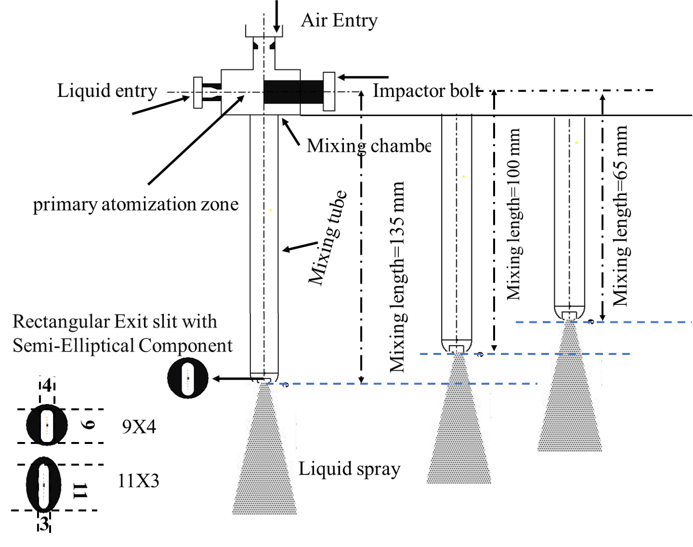
Beneath the mixing chamber lies a lengthy cylindrical structure with a 12.5 mm inner diameter, serving as the conduit for the expelled mixture into the spray chamber post-passing through a honeycomb structure. Different lengths of the conduit were designed, and the size of the elliptic slit was varied from 9 mm x 4 mm to 11 mm x 3 mm. The effects of the mixing length and slit area were investigated, and the optimal injector was selected based on the findings of this study. The interaction between the incoming water and air initiates primary breakup within the mixing chamber, aided by the impactor bolt's strategic positioning. By aligning the bolt to the center of the air injection orifice, heightened interaction between water and air is achieved, thereby elevating the atomizing prowess of this pioneering atomizer.
The experimental setup encompasses a comprehensive water and air delivery system alongside an injector assembly, exemplified in the design depicted in Fig. 2. Central to this arrangement is the spray chamber, measuring 0.75 m x 0.75 m x 1.25 m, equipped with optical access, meticulously tailored for Particle Doppler particle Analyzer as well as visualization experiments. Positioned atop the spray chamber, the assembled injector serves as the focal point for evaluating atomization performance across various spatial and operational conditions. Water is propelled to the injector from a dedicated tank via compressed air, with pressure regulation facilitated by a pressure regulating valve and digital gauge. To mitigate mist formation within the test section and prevent interference with both the primary spray and optical measurements, a honeycomb structure is strategically deployed at the spray chamber's base, as illustrated in Fig. 2.
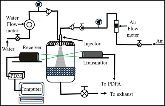
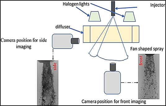
Water delivery, facilitated by compressed air, is closely monitored through a water flow meter, ensuring precise control and measurement of flow rates. Conversely, the compressed air, filtered and dried by a moisture separator and air heater, is supplied from a storage tank via a high-pressure conduit, regulated by a rotameter, needle valve, and pressure regulating valve. Density adjustments are meticulously calibrated by monitoring pressure levels with a gauge boasting 1% full-scale accuracy. For further insights into the Phase Doppler Particle Analyzer (PDPA), refer to the detailed description provided in references [42-43]. Figure 3 presents a schematic diagram of the setup for high-speed imaging. A high-speed camera was employed to capture images of the spray from both the front and side views, as the spray exhibits a fan shape with significant thickness, rather than forming a complete or hollow cone. To illuminate the area of interest, two halogen lights were used. A diffuser was positioned between the light sources and the camera to ensure uniform light intensity and prevent direct light from reaching the lens. A total of 500 images were captured at a resolution of 1000 x 1200 pixels over a period of 1 second, with an exposure time of 5 µs to adequately capture the spray dynamics.
The atomizing performance was systematically investigated through three distinct experimental scenarios. In the initial case, the liquid flow rate and injection pressure remained constant while the air flow rates, coupled with air pressure, were systematically varied, resulting in a range of non-dimensional air-to-liquid mass ratios spanning from 0.09 to 0.12. The crucial parameter under scrutiny is the Air-to-Liquid Mass Ratio (ALR), defined as the ratio of air mass flow rate to liquid mass flow rate and given by ![]() . Subsequently, in the second case, the air flow rate was held constant at approximately 5.5 x 10^-3 kg/s, while the liquid flow rate was incrementally increased from 0.05 to 0.22 kg/s. In this investigation aimed to discern the impact of varying liquid flow rates on atomization effectiveness. in the third case, the effect of mixing lengths and exit slit size were investigated. The air flow rates were varied from 1.87x10^-3 kg/s to 3.37X10^-3 kg/s while keeping water flow rates near about constant while changing water injection pressure. The ALR were calculated in the range of 0.03 to 0.08. The detailed operational conditions for the investigated injector are meticulously outlined in Tables 1, 2 and 3, providing comprehensive insight into the experimental test operating conditions under scrutiny.
. Subsequently, in the second case, the air flow rate was held constant at approximately 5.5 x 10^-3 kg/s, while the liquid flow rate was incrementally increased from 0.05 to 0.22 kg/s. In this investigation aimed to discern the impact of varying liquid flow rates on atomization effectiveness. in the third case, the effect of mixing lengths and exit slit size were investigated. The air flow rates were varied from 1.87x10^-3 kg/s to 3.37X10^-3 kg/s while keeping water flow rates near about constant while changing water injection pressure. The ALR were calculated in the range of 0.03 to 0.08. The detailed operational conditions for the investigated injector are meticulously outlined in Tables 1, 2 and 3, providing comprehensive insight into the experimental test operating conditions under scrutiny.
Table 1. Operating conditions for case 1
|
pl |
pa |
|
|
ALR |
|
273.69 |
515.01 |
0.005 |
0.051 |
0.098 |
|
273.69 |
721.85 |
0.006 |
0.051 |
0.120 |
|
273.69 |
928.69 |
0.006 |
0.051 |
0.119 |
Table 2. Operating conditions for case 2
|
pl |
pa |
|
|
ALR |
|
225.43 |
652.9 |
0.0055 |
0.026 |
0.22 |
|
294.38 |
652.9 |
0.0055 |
0.05 |
0.11 |
|
273.69 |
652.9 |
0.0055 |
0.076 |
0.07 |
|
356.43 |
652.9 |
0.0055 |
0.1 |
0.05 |
Table 3. Operating conditions for case 3
|
pl |
pa |
|
|
ALR |
|
225.43 |
515.01 |
0.00187 |
0.051 |
0.037 |
|
232.32 |
515.01 |
0.00262 |
0.051 |
0.051 |
|
239.22 |
515.01 |
0.00337 |
0.051 |
0.07 |
|
253.01 |
515.01 |
0.00413 |
0.051 |
0.08 |
3. 4. Measurements points and impactor positions:
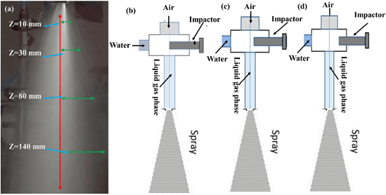
To comprehensively assess the atomizing capabilities of the newly devised injector, three distinct cases were meticulously examined, as elaborated in the preceding section 3.3. In the first case, measurements were systematically taken along the spray's central axis, commencing 10 mm downstream of the injector and proceeding at 10 mm intervals up to 140 mm. In the second case, measurements were focused on four specific downstream positions (z=10 mm, z=30 mm, z=80 mm, and z=130 mm). Proximate to the atomizer exit, two positions were selected to encompass the primary atomization region, gradually traversing radially from the spray's center to its periphery at 2 mm increments. Conversely, farther downstream from the atomizer exit, two additional positions were chosen to encapsulate the secondary breakup region, extending from the center to the outer periphery at 3 mm intervals, as illustrated in Figure 4 (a). The impactor bolt's influence on atomizer performance was meticulously investigated by exploring three distinct bolt positions depicted in Figure 4 (b), (c), and (d). In the first configuration, the impactor is situated near the center of the mixing chamber, or equivalently, the midpoint between the air inlet and mixture outlet. Subsequently, the bolt was adjusted 5 mm away from the center for the second position, and again for the third position. These variations in impactor positioning alter the manner in which air impinges upon the liquid surface, potentially influencing the interaction between air and the liquid jet, thus directly impacting atomizing performance and the atomization process overall. The presence of the impactor bolt within the air-water injection zone may ultimately augment the capabilities of the investigating injector.
4. Results and discussions
Within the intricate dynamics of the spray system, droplet diameters were analysed using two distinct parameters: the mean diameter, reflecting the average size across the spatial expanse of the spray, and the Sauter diameter, which quantifies the volume-to-surface area ratio. These measurements are crucial for a comprehensive understanding of spray behaviour. While the initial breakup of liquid jets primarily occurs within the mixing chamber, the main focus of the study lies within the secondary atomization breakup region. Nonetheless, special attention is given to the vicinity of the injector's injection tip, where the spray exhibits a tightly compacted nature, posing challenges in accurately assessing droplet size and distribution. This study meticulously presents data collected at various downstream and radial positions from the injection tip.
4. 1. Centreline variation
Figures 5 (a) and (b) offer a comprehensive visualization of the Sauter mean diameter variations along the spray centerline at various Air-liquid mass ratios. The illustrated data reveals distinct zones that delineate the evolving dynamics of the spray. In the initial zone, extending up to 40 mm from the injector's tip, droplet sizes exhibit an increasing trend along the axial direction. This region presents challenges in accurate droplet size prediction due to the dense and compact nature of the spray. The presence of numerous non-spherical particles, unaccounted for by the Phase Doppler Particle Analyzer (PDPA), contributes to notably low data capture rates in this dense region. Moving downstream, a second zone emerges characterized by radial dispersion, likely induced by the formation of ligaments or larger droplets. This region, termed the atomizing zone or zone II, witnesses a decrease in droplet sizes with downstream progression until reaching a critical stage where further reduction becomes unlikely. Observations reveal a gradual increase followed by a decrease in D32 within zone 1, with minor fluctuations attributable to a mixed mode encompassing column and surface breakup modes. Similar fluctuations are observed across various air-to-liquid mass ratios, indicating the presence of mixed modes leading to the simultaneous formation of fine and large droplets, resulting in fluctuating trends in SMD variation. Subsequent analysis delves into the breakup mechanisms influencing droplet formation and dynamics. In the third zone, also known as the critical zone, the spray reaches a point where no further significant reduction in droplet size occurs.
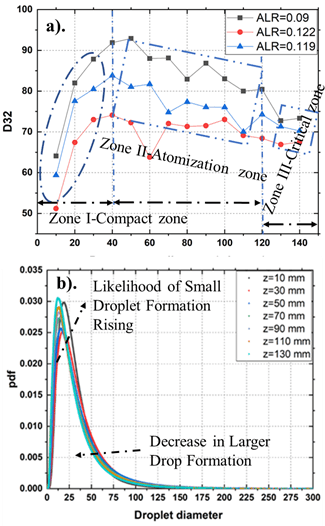
Further insights are gleaned from the probability density function of droplet size and velocity distributions depicted in Figure 5 (b). The probability density functions analysis confirms a leftward skew and upward peak shift in size distribution with downstream progression, signifying a decrease in droplet size and an increasing number of droplets. Figures 6 (a) and (b) further elucidate the centerline variation of mean droplet velocities, depicting a gradual decrease in axial velocity with downstream locations within the atomized zone.
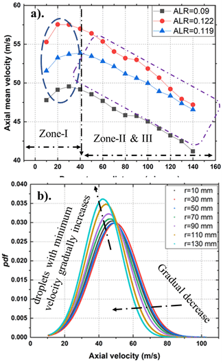
Similarly, the probability density function of axial mean velocity displays a leftward skew and upward peak shift with downstream distance, indicating a reduction in droplet mean velocity and an increased prevalence of droplets dominating streamwise spray transport.
4. 2. Radial variation
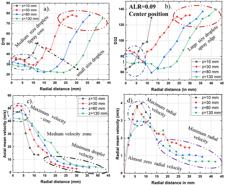
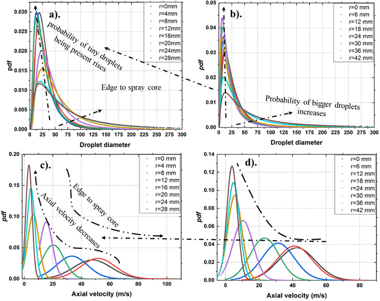
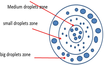
Figure 7 illustrate the radial evolution of droplet size and axial mean velocity at various downstream positions at ALR=0.09. Droplet sizes exhibit a gradual decrease from the spray core towards the edges, followed by an increase as one approach the periphery. Notably, the bigger droplets are observed at the peripheral locations of the spray. This behavior is characteristic of a swirl injector, where centrifugal forces propel larger droplets outward. The radial variation of droplet size delineates three distinct zones: the spray core, characterized by medium-sized droplets with higher axial velocity; the fine zone, comprising smaller or very fine droplets with moderate velocities; and finally, the outer zone, where larger droplets with lower velocities are observed, likely due to coalescence or radial dispersal of larger droplets. These zones and their corresponding droplet classes are depicted in Figure 9. Examining the radial variation of droplet velocities, as depicted in Figure 7 (c) and (d), reveals that axial velocity peaks in the core zone and gradually decreases towards the edges. In zone 2, axial mean velocity decreases nearly linearly with radial distance, while in zone 3, it decreases gradually or remains relatively constant. Figure 8 depicts the probability density function of droplet and velocity distribution at two downstream distances, z=30 mm, and z=130 mm, from the spray center towards the spray edges. droplet distribution behavior was observed at both locations (z=30 mm and z=130 mm), with skewness continually decreasing, indicating the formation of larger droplets through coalescence or aggregation, which may or may not involve separation and exhibit significant drag, resulting in momentum loss. The data clearly shows that the mean axial velocity of droplets reaches its peak in the spray core, gradually decreasing to its minimum at both downstream locations, as illustrated in figures 8 (c) and (d).
4. 3. Impact of liquid Flow Rates
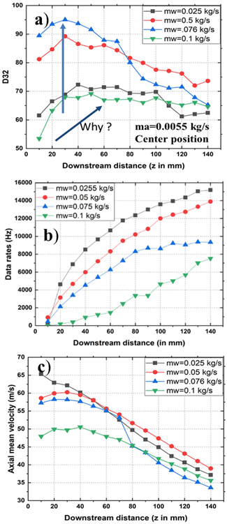
Figure 10 present the effect of liquid (water) flow rates on droplet characteristics, including sizes, velocities, and droplet data rates across various downstream locations. Specifically, it illustrates the axial variation of the SMD of droplets for different liquid flow rates while maintaining a constant air flow rate, as shown in figure 10 (a). At lower liquid flow rates, the SMD gradually decreases, indicating ongoing secondary atomization processes without reaching the critical stage at the target locations. Conversely, at higher liquid flow rates, droplets appear to achieve the critical stage, resulting in uniform or minimally affected sizes, suggesting the completion or near-completion of secondary atomization. Notably, droplet size increases with liquid flow rates, with a significant decrement observed at lower flow rates due to higher energy transfer, while larger flow rates exhibit a more gradual decrease in Sauter mean diameter, approaching the critical stage. Consistently, droplet velocities as shown in figure 10 (c) decrease with increasing water flow rates, reflecting the greater energy required for atomization at higher flow rates and consequently less momentum attained by droplets compared to lower flow rates. Figure 10 (b) displays the variation in droplet data rates at different downstream positions for various liquid flow rates. Generally, droplet data rates exhibit a logarithmic increase with liquid flow rates, except at high flow rates (![]() =0.1 kg/s), where an almost linear increase is observed. This trend suggests an enhanced formation of spherical particles with downstream progression, indicative of improved atomization levels or containing the secondary atomization or breaking of bigger droplets into smaller daughters drops, while the number of tiny particles decreases with increasing flow rates. Overall, higher liquid flow rates adversely affect atomization quality, leading to a reduced rate of tiny droplet generation as a result higher in droplets size.
=0.1 kg/s), where an almost linear increase is observed. This trend suggests an enhanced formation of spherical particles with downstream progression, indicative of improved atomization levels or containing the secondary atomization or breaking of bigger droplets into smaller daughters drops, while the number of tiny particles decreases with increasing flow rates. Overall, higher liquid flow rates adversely affect atomization quality, leading to a reduced rate of tiny droplet generation as a result higher in droplets size.
4. 4. Effect of Impactor positions
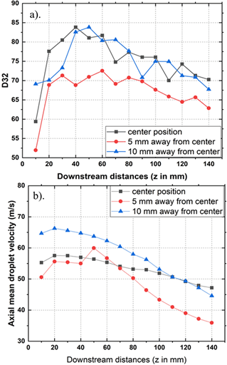
In figure 11 (a) displays the axial distribution of Sauter Mean Diameter (SMD) across different impactor positions. Notably, a reduction in droplet size is observed, particularly within the atomized and critical zones, when the impactor is positioned 5 mm away from the center. This reduction is likely attributed to heightened shearing forces and droplet stripping, leading to the breakup of the liquid sheet column and surface, ultimately yielding finer droplets. In figure 11 (b), the variation in droplet axial mean velocity is depicted, revealing higher velocities associated with injector positions located 10 mm away from the center compared to other positions. This discrepancy arises. from the significant shift in the spray axis caused by the presence of the impactor bolt. Consequently, the spray trajectory adjusts in a direction opposing the positioning of the impactor bolt, thereby influencing the atomization dynamics of the injector.
4. 5. Liquid-Air Interactions
Figures 12 (a), (b), and (c) depict the water-air interaction dynamics for all three positions of the impactor bolt within the present atomizer setup. This interaction is particularly pronounced, leading to the breakup of the liquid jet column within the interaction chamber by the high-speed transverse air jet acting on a conical liquid column. In Figure 12 (a), the impactor bolt locations are situated almost at the center of the forthcoming air-jet injection orifice. As a result, the airflow deviates from its intended path due to the presence of the bolt. This deviation fosters a robust interaction between the air and water jets, with the air effectively enveloping a substantial portion of the water jet's interaction area. Consequently, both column and surface breakup modes become more prevalent, thereby enhancing the atomizer performance of the current injector by reducing droplet size and velocities. Moving to Figure 12 (b), the bolt is positioned 5 mm away from the center of the air injection orifice. Here, there is less interaction between air and water, with minimal deviation of the upcoming air jet from its intended flow field compared to the previous configuration. Consequently, column breakup becomes more dominant while surface breakup is less pronounced, as the diverted air flow strips off fewer droplets. Lastly, Figure 12 (c) illustrates the impactor bolt positioned 10 mm away from the center of the air injection orifice.
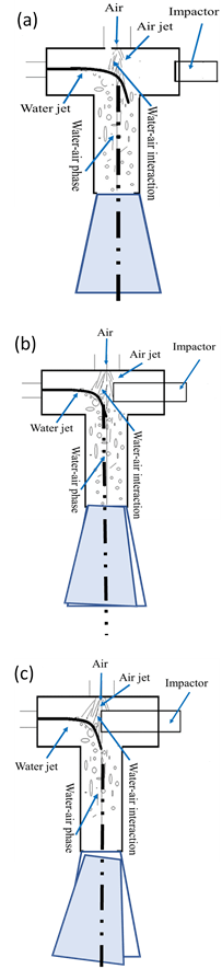
In this configuration, there is no direct constriction in the airflow path. The air jet directly interacts with the water column, fracturing it into large chunks and droplets. Here, only the column breakup mode is predominant. With no loss of air momentum, droplet velocities attain high axial velocity due to significant momentum exchange. These large chunks subsequently mix with air and undergo further breakup into droplets, contributing to the overall mixing phases within the cylindrical passage.
4. 6. Effect of Injector’s mixing length and Slit size
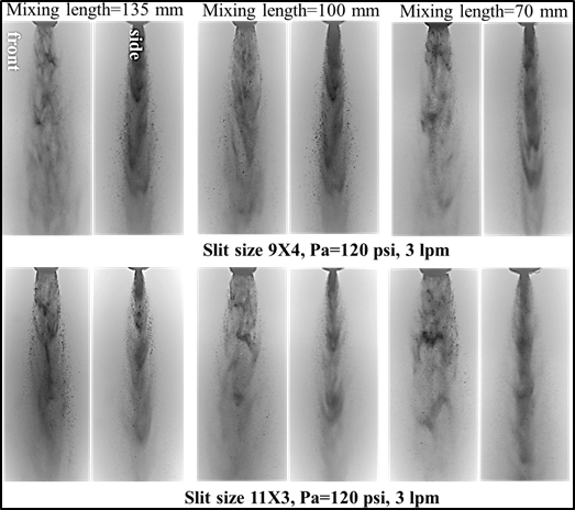
Figures 13 and 14 present instantaneous images showing the effects of different slit sizes within the injector under various air injection pressures, with consistent liquid supply parameters. Figure 13 illustrates the side and front views of the spray with different mixing lengths and slit sizes at a water flow rate of ![]() =0.051 kg/s and an air pressure of 𝑃𝑎=514.6 kPa. As expected, larger slit sizes result in increased spray dispersion, particularly noticeable in the front view, while the side view shows comparatively less dispersion for the 9x4 slit size injector. This indicates that larger slit sizes can enhance the atomization process, producing smaller droplets compared to the 9x4 slit size injector. For both injector types, Figure 14 reveals that even at higher air injection pressures and air flow rates, the spray formed from a longer mixing length appears relatively symmetric, which helps in achieving uniform drop distribution across the spray. Conversely, at shorter mixing lengths, the waves are more asymmetric, leading to non-uniform drop distribution.
=0.051 kg/s and an air pressure of 𝑃𝑎=514.6 kPa. As expected, larger slit sizes result in increased spray dispersion, particularly noticeable in the front view, while the side view shows comparatively less dispersion for the 9x4 slit size injector. This indicates that larger slit sizes can enhance the atomization process, producing smaller droplets compared to the 9x4 slit size injector. For both injector types, Figure 14 reveals that even at higher air injection pressures and air flow rates, the spray formed from a longer mixing length appears relatively symmetric, which helps in achieving uniform drop distribution across the spray. Conversely, at shorter mixing lengths, the waves are more asymmetric, leading to non-uniform drop distribution.
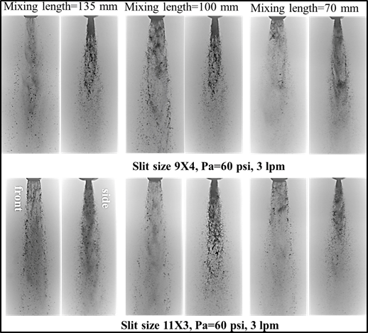
Longer mixing lengths promote better atomization with greater uniformity, resulting in smaller droplets due to improved mixing and momentum exchange between the liquid and air phases. The qualitative analysis aids in understanding the atomization process more effectively.
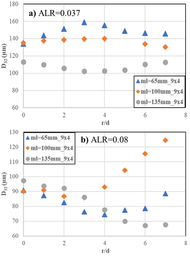
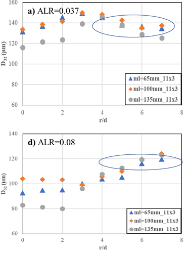
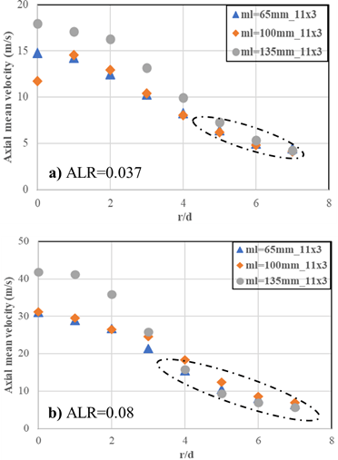
Figure 15 illustrates the radial comparison of drop size variation for the 9x4 slit size injector with different mixing lengths at lower (ALR=0.03) and higher ALR (ALR=0.8). It is noteworthy that at lower ALR, the Sauter Mean Diameter decreases with increasing mixing length. Conversely, at higher ALR, a mixing length of 65 mm demonstrates improved atomization performance, indicating its effectiveness in achieving superior atomization. The increased mixing length facilitates a stronger exchange between air and liquid, leading to a rise in mean velocity. In contrast, figure 16 shows the radial comparison of drop size variation for the 11x3 slit size injector with various mixing lengths at lower (ALR=0.03) and higher ALR (ALR=0.8). It is observed that for the reduced slit size, droplet SMD decreases with increasing mixing length. Moving on to figure 17, it presents a comparison of droplet axial mean velocity for the 9x4 slit size injector at two ALR values, revealing an increase with increasing mixing lengths. Conversely, figure 18 depicts the comparison of droplet velocities for various mixing lengths using an 11x3 slit size injector. Across all locations, the mean velocity increases with escalating ALR (Air-to-Liquid Ratio). Interestingly, as the mixing length increases, there is a corresponding rise in mean velocity, except for mixing lengths of 100 mm and 65 mm, where the velocity appears to remain relatively constant regardless of ALR.
Significantly, at peripheral locations, the influence of mixing length on mean velocity diminishes, with shorter lengths showing a less pronounced impact compared to longer ones.
5. Conclusion
The current study delves into the spray characteristics generated by a newly designed twin-fluid injector specifically tailored for modern risers in the FCC system. Within the mixing chamber, the primary breakup of the liquid jet predominantly occurs, driven by aerodynamic forces from impinging air. Notably, positioning the impactor bolt 5 mm away from the center of the air injection orifice enhances turbulence in the flow field, fostering increased mixing and interaction with the liquid jet. This dynamic leads to the prevalence of both surface and column breakup modes, resulting in reduced droplet size and velocities, thus enhancing overall atomization efficiency. Conversely, when the impactor bolt is displaced further from the center of the air injection orifice, the air jet tends to follow a more linear trajectory, diminishing mixing, turbulence, and interaction levels. Consequently, less momentum is transferred to the liquid phase, resulting in diminished atomizing energy and larger droplet sizes. At considerable distances from the air injection orifice, the dominance of the column breakup mode becomes evident. Furthermore, higher liquid flow rates lead to increased spray density, resulting in reduced droplet population density and lower data rates, particularly noticeable at higher water flow rates. This discrepancy raises concerns about the accuracy of measured Sauter Mean Diameter at higher flow rates. Finally, the formed spray exhibits three distinct classes of droplet size distribution: medium-sized droplets within the core region, characterized by higher velocities due to their large inertia-to-drag ratio; larger-sized droplets near the spray edges, displaying lower inertia-to-drag ratios and inability to synchronize with airflow; and smaller-sized droplets occupying the intermediate zone of the core and the spray edges. Increasing mixing length decreases droplet size at lower Air-to-Liquid Ratio, while a 65 mm mixing length enhances atomization at higher ALR, resulting in improved mean velocity. Droplet size decreases with increasing mixing length, particularly notable in the core region, indicating enhanced atomization. Despite differences in slit size, both configurations exhibit a similar trend of decreasing droplet size with increasing mixing length, particularly noticeable in the core region, suggesting improved atomization. Hence, the effect of slit size on the outcomes appears to be less significant compared to the impact of mixing length.
References
[1] M.M. Denn, "Process Fluid Mechanics," Prentice-Hall, NJ, 1980.
[2] P.B. Venuto, E.T. Habib, "Fluid Catalytic Cracking with Zeolite Catalysts," Marcel Dekker, New York, 1979.
[3] K.N. Theologos, A.I. Lygeros, N.C. Markatos, "Feedstock atomization effects on FCC riser reactors selectivity", Chem Engg Sci., vol. 54, no. 22, pp. 5617-5625,1999. View Article
[4] C. Mirgain, C. Briens, M.D. Pozo, "Modeling of Feed Vaporization in Fluid Catalytic Cracking. Ind Eng", Chem Res., vol. 39, no.11, pp. 4392-4399, 2000. View Article
[5] A. Gupta and D.S. Rao, "Model for the performance of a fluid catalytic cracking (FCC) riser reactor: effect of feed atomization", Chem Eng Sci., vol. 56, no. 15, pp. 4489-4503, 2001. View Article
[6] Chan et al. "Fluid injection nozzle for fluid bed reactors," U.S. patent 8, 999, 246B2, 2015.
[7] S. Ariyapadi, F. Berruti, C. Briens, J. McMillan, D. Zhou, "Horizontal penetration of gas-liquid spray jets in gas-solid fluidized beds," Int. J. Chem. React. Eng., vol. 2, no. 1, 2004. View Article
[8] Z. Huang and T.C. Ho, "Effect of thermolysis on repsid droplet vaporization in fluid catalytic cracking" Chem. Eng. J., vol. 9, pp. 45-58, 2003. View Article
[9] A. Gupta and D.S. Rao, "Effect of feed atomization on FCC performance: simulation of entire unit," Chem. Eng. Sci., vol. 58, pp. 4567-4579, 2003. View Article
[10] K. W. Ku, J. G Hong, C. W. Park, "Effect of Assist-air of Twin Fluid Atomizer on Urea Thermal Decomposition," Atomization and Sprays, vol. 25, pp. 895−915, 2015. View Article
[11] S.C. Ju and X.W. Li, "Experimental study on Internal Mixing Sonic Flow Air Assist Atomizer for Heavy Oils". In: International Gas Turbine and Aeroengine Congress and Exposition, June 11, 1990-June 14, Brussels, Belg: ASME, p. T6, 1990.
[12] M. i, and G. Wozniak, "Experimental investigation of spray characteristics of pre-filming air-blast atomizers," Journal of Applied Fluid Mechanics, vol. 11, no.6, pp.1455-1469, 2018. View Article
[13] A.H. Lefebvre, "Airblast Atomization," Progress in Energy and Combustion Sciences, vol.6, no.502, pp.223-261, 1980. View Article
[14] S.D. Sovani, P.E. Sojka and A.H. Lefebvre, "Effervescent Atomization," Progress in Energy and Combustion Sciences, vol. 27, pp. 483-521, 2001. View Article
[15] H.N. Buckner, P.E. Sojka, and A.H. Lefebvre, "Effervescent atomization of coal-water slurries," ASME publication, vol. 30, pp. 105-108, 1990a.
[16] A.H. Lefebvre, "Twin-Fluid Atomization: Factors Influencing Mean Drop Size," Atomization and Sprays, vol. 2, pp. 101-119, 1992. View Article
[17] S.H. Song, S. Y. Lee, "Study of Atomization Mechanism of Gas/ Liquid Mixtures Flowing through Y-Jet Atomizers," Atomization Sprays, vol. 6, pp.193−209, 1996. View Article
[18] Y.H. Nazeer, M. Ehmann, P. Koukouvinis, M. Gavaises, "The influence of geometrical and operational parameters on internal flow characteristics of internally mixing twin-fluid y-jet atomizers," Atomization Sprays, vol. 29, pp. 403−428, 2019. View Article
[19] S. Song and S. Lee, 1994, "An examination of spraying performance of y-jet atomizers- effect of mixing port length," Rouen, International Conference on Liquid Atomization and Spray Systems.
[20] Y.H. Nazeer, M. Ehmann, P. Koukouvinis, & M. Gavaises, "The Influence of Geometrical and Operational Parameters on Internal Flow Characteristics of Internally Mixing Twin-Fluid Y-Jet Atomizers," Atomizations & Sprays, vol. 59, no. 5, pp. 403-428, 2019. View Article
[21] Z. Li, et al., "Mixing and atomization characteristics in an internal-mixing twin-fluid atomizer," Fuel, vol. 97, pp.306-314, 2012. View Article
[22] A. Kushari, "Effect of injector geometry on the performance of an internally mixed liquid atomizer". Fuel Process Technol. vol. 91, no.11, pp.1650-4, 2010. View Article
[23] J. C. Thompson, and J. P.: Rothstein, "The atomization of viscoelastic fluids in flat-fan and hollow-cone spray nozzles," J. Nonnewton. Fluid Mech., vol. 147, pp. 11-22, 2007. View Article
[24] Q. Zhou, P. C. H., Miller, P. J. Walklate, and N. H. Thomas, "Prediction of Spray Angle from Flat Fan Nozzles," J. Agric. Eng. Res., vol. 64, no. 2, pp.139-148, 1996. View Article
[25] L.J. Guo, G.J Li., B. Chen, X.J. Chen, D.D. Papailiou, and T.h. Panidis, "Study on gas-liquid two-phase spraying characteristics of nozzles for the humidification of smoke," Exp. Therm. Fluid Sci., vol. 26, pp. 715-722, 2002. View Article
[26] A.H. Lefebvre and J.S Chin., "Flow patterns in internal-mixing, twin-fluid atomizers," Atomization Sprays, vol. 3, no.4, pp. 463-75, 1993. View Article
[27] A. Kushari, Y. Neumeier, O. Israeli, E. Lubarsky, B.T Zinn., "Internally mixed liquid injector for active control of atomization process", J. Propul. Power, vol. 4, no. 17, pp. 878-82, 2001. View Article
[28] A. Kushari, "A Phenomenological Two-Phase Flow Model of Atomization in an Internally Mixed Liquid Atomizer," Int. J. Turbo Jet Engines, vol. 24. pp. 183-194, 2007. View Article
[29] S.C. Ju and X.W. Li., "Experimental study on Internal Mixing Sonic Flow Air Assist Atomizer for Heavy Oils,"International Gas Turbine and Aeroengine Congress and Exposition, June 11-June 14, Brussels, Belg: ASME, p. T6, 1990.
[30] S. Kim, S. Kondo, K. Nishida, H. Hiroyasu, "Effects of mixing chamber geometry and flow on spray characteristics from an internal mixing twin-fluid atomizer'" Int. J. Fluid Mech. Res, vol. 24, pp.76-87, 1997. View Article
[31] D.A Nguyen and M.J. Rhodes, "Producing Fine Drops of Water by Twin-Fluid Atomisation," Powder Technol., vol. 99, no. 3, pp. 285-92, 1998. View Article
[31] Nguyen D.A., Rhodes M.J., 1998 "Producing Fine Drops of Water by Twin-Fluid Atomisation". Powder Technol. 99(3):285-92. View Article
[32] A. Kufferath, B Wende and W. Leuckel, "Influence of liquid flow conditions on spray characteristics of internal-mixing twin-fluid atomizers," International journal of heat and fluid flow, Volume 20, pp. 513-519, 1999. View Article
[33] J. Karnawat and A. Kushari., "Controlled atomization using a twin-fluid swirl atomizer," Exp. Fluids, vol. 41, no. 4, pp. 649-63, 2006. View Article
[34] J. Karnawat and A. Kushari, "Spray evolution in a twin-fluid swirl atomizer," Atomization Sprays, vol 18, no. 5, pp. 449-70, 2008. View Article
[35] G. Ferreira, F. Barreras, A. Lozano, J.A. Garcia, E. Lincheta, "Effect of the inner twin-fluid nozzle with an internal mixing chamber," Atomization Sprays, vol. 19, no. 9, pp. 873-84, 2009. View Article
[36] G. Ferreira, J.A Garciia, F. Barreras, A. Lozano, E Lincheta, "Design Optimization of Twin-Fluid Atomizers with an Internal Mixing Chamber for Heavy Fuel Oils". Fuel Process Technol. vol. 90, no.2. pp. 270-8, 2009. View Article
[37] J.A. García, A. Lozanoet, J. Alconchel, E. Calvo, F. Barreras, J.L. Santolaya, "Atomization of glycerin with a twin-fluid swirl nozzle," Int. J. Multiph. Flow, vol. 92, pp.150-160, 2017. View Article
[38] S. Lal, A. Kushari, M. Gupta, J. C. Kapoor, S. Maji, "Experimental study of an air-assisted mist generator". Exp Therm. Fluid Sci. vol. 34, no. 8, pp.1029-35, 2010. View Article
[39] L. Broniarz-Press, M Ochowiak, J. Rozanski, S Woziwodzki, "The atomization of water-oil emulsions," Exp Therm Fluid Sci., vol. 33, no.6, pp. 955-62, 2009. View Article
[40] Li et al., "Effect of Liquid Viscosity on Atomization in an Internal-Mixing Twin-Fluid Atomizer," Fuel, vol 103, pp. 486-494, 2013. View Article
[41] C. E. Ejim, M. A. Rahman, A. Amirfazli, and B. A. Fleck, "Effects of liquid viscosity and surface tension on atomization n two-phase, gas/liquid fluid coker nozzles," Fuel, vol. 89, no. 8, pp. 1872-1882, 2010. View Article
[42] D. Kumar, T. Sikroria, A. Kushari, P. Kumar, and G. Sriganesh, "A twin-fluid injector for FCC feed injection," Int J Petrochem Sci Eng., vol. 4, no. 3, pp. 109-115, 2019. View Article
[43] D. Kumar, T. Sikroria, A. Kushari, P. Kumar, and G. Sriganesh, "Spray characteristics from a twin-fluid atomizer with internal impactor" ILASS-Asia 2016, 18th Annual Conference on Liquid Atomization and Spray Systems - Asia, Chennai, India. 6- 9 Nov. 2016.