Journal of Fluid Flow, Heat and Mass Transfer (JFFHMT)
ISSN: 2368-6111

Volume 11 - Year 2024 - Pages 197-209
DOI: 10.11159/jffhmt.2024.020
A Computational Investigation of Mist Film Cooling Efficiency Using Novel Trench-Shaped Holes
Abhishek Verma1,, Debi Prasad Mishra2
1Department of Aerospace Engineering, Indian Institute of Technology Kanpur, Uttar Pradesh 208016, India
2Department of Mechanical Engineering, National Institute of Technical Teachers’ Training and Research Kolkata, WB 700106, India
First.abhishv@iitk.ac.in; Second. mishra@iitk.ac.in
Abstract - A two-phase numerical investigation on trench-shaped injection holes for film cooling is being conducted using Reynolds-averaged Navier-Stokes simulations to assess their practical effectiveness. The study focuses on the cooling performance of a novel type of film hole, known as straight transverse trenches attached to a flat plate, using a mixture of water mist and air in the coolant fluid. The examination considers film cooling with varying turbulent intensities (3%, 10%, and 20%) and mist concentrations (4%, 7%, and 10%). The analysis involves adiabatic laterally averaged and area-averaged (overall) mist film cooling effectiveness parameters, with two blowing ratios ranging from 0.6 to 1.0. The findings indicate that trenched cooling holes exhibit a more uniform coolant distribution laterally at all positions especially at higher mist concentrations, resulting in enhanced cooling performance, particularly at high blowing ratios.
Keywords: Film-cooling, effectiveness, mist, trench-hole, turbulent.
© Copyright 2024 Authors - This is an Open Access article published under the Creative Commons Attribution License terms Creative Commons Attribution License terms. Unrestricted use, distribution, and reproduction in any medium are permitted, Pr ovided the original work is Pr operly cited.
Date Received: 2024-02-02
Date Revised: 2024-05-21
Date Accepted: 2024-06-03
Date Published: 2024-07-29
Nomenclature
|
Ap |
Surface area of the droplet |
|
BR |
Blowing ratio |
|
CD |
Drag coefficient |
|
Cj |
Concentration of species j |
|
Cμ |
Model constant |
|
D |
Injection hole diameter (mm) |
|
Deff |
Effective mass diffusivity |
|
FD |
Drag force per unit particle mass |
|
H |
Heat transfer coefficient |
|
hfg |
Latent heat of vaporization |
|
keff |
Effective thermal conductivity |
|
Prt |
Turbulent Prandtl number |
|
Mc |
Mist concentration (%) |
|
ReD |
Reynolds number for droplet motion |
|
Sh |
Source term for heat |
|
Sj |
Source term for species j |
|
T |
Temperature |
|
Tc |
Coolant temperature at plenum inlet |
|
T∞ |
Main-stream temperature at |
|
Taw |
Adiabatic wall temperature |
|
Tbp |
Boiling point of the droplet |
|
Tu |
Turbulent intensity |
|
Tvap |
Vaporization temperature of the droplet |
|
η |
Local film cooling effectiveness |
|
ηav |
Laterally averaged film cooling effectiveness |
|
ε |
Dissipation rate of turbulent kinetic energy |
|
k |
Turbulent kinetic energy |
|
μ |
Dynamic viscosity |
|
μeff |
Effective viscosity |
|
μt |
Turbulent viscosity |
|
ρ |
Density |
|
ui |
Velocity component in the i-th direction |
|
up |
Droplet velocity |
|
cp |
Specific heat at constant pressure |
|
Cp, p |
Specific heat of the droplet at constant pressure |
|
dp |
Droplet diameter |
|
mp |
Droplet mass |
|
Reynolds stress for concentration |
|
|
Reynolds stress for temperature |
1. Introduction
Trenched holes, employed in diverse applications such as industrial furnaces and gas turbine components, epitomize an advanced film cooling technique [1–3]. In this method, the coolant injection hole opening is intricately linked to a longitudinal groove carved into the surface exposed to the hot mainstream gas [4,5]. The primary objective of incorporating the trench is to alleviate vortex formation in close proximity to the injection orifice, effectively diminishing coolant film separation and averting lift-off from the surface [6–8]. In the current scenario, the presence of a trench mitigates severe coolant jet separation, resulting in elevated film cooling efficiency [9,10]. Conversely, without a trench, the coolant's penetration into the mainstream flow renders a significant portion ineffective. The absence of a trench triggers downstream vortex formation, a phenomenon well-documented by previous researchers, which is notably alleviated with the incorporation of a trench, leading to improved effectiveness. Turbulence levels were examined, revealing isotropy for all turbine blades. Film cooling induces higher turbulence compared to conventional cylindrical holes. Trenched holes consistently exhibit superior adiabatic effectiveness, even at low blowing ratios, suggesting enhanced gas turbine performance [11]. Sunderam and Thole [5] conducted a study focusing on the leading-edge region of a stator vane in a gas turbine, where high heat transfer rates occur due to horseshoe vortices. This research delved into the flow field dynamics in the presence of an interface slot and film-cooling jets. The study considered conditions with no film-cooling holes or upstream slots, film-cooling holes with an interface slot, and film-cooling holes in a trench with an interface slot. Results unveiled the formation of a second vortex in the presence of film-cooling holes and a slot, accompanied by heightened turbulence intensity. In the same study, measurements at a high blowing ratio (BR=2.5) disclosed variations in flow field characteristics at the leading edge. In a separate investigation, Kalghatgi and Acharya [6,8] introduced an innovative design featuring a round film cooling hole embedded in a contoured crater, aiming to amplify film cooling effectiveness. The contour is strategically designed to weaken the kidney-pair vortex generated by the film cooling jet. He et al. [12] explored film cooling and aerodynamic losses in a turbine guide vane, evaluating three structures: standard cylindrical film holes, traverse trench, and segmented trench. The study revealed that coolant momentum in trenches rose with mainstream momentum, yet misalignment resulted in lateral spread, particularly at high BR and low Mach regions. Trenched holes exhibited higher discharge coefficients at low BR, with comparable total pressure losses to cylindrical holes. Harrison et al. [13] previously investigated net heat flux reduction and found it to be significantly higher for trenches compared to cylindrical holes. The study examined four reference conditions, highlighting distinct distributions of heat transfer coefficients. Additionally, the researchers studied film cooling and heat transfer in a simulated turbine vane with cylindrical holes placed in a transverse trench on the suction side. The results showed increased heat transfer augmentation for untripped approach flow, especially with upstream heating, reaching up to 180% for the trench. In contrast, tripped approach flow exhibited lower levels of augmentation. Zhang et al. [2] investigated the impact of serrate structure on the film cooling performance of trenched holes using a mist/air mixture. Results revealed that the included angle of serrate significantly influenced WFCE, showing an initial increase and subsequent decrease with rising BR’s. Mist concentration and droplet diameter played crucial roles in affecting Wet-bulb-temperature-based film cooling effectiveness (WFCE). The study affirmed that the serrated transverse trench structure, combined with mist injection, significantly improved film cooling performance under practical conditions for a turbine vane. Baheri et al. [14] conducted a comparative-numerical investigation on film cooling from simple and compound-angle holes injected at 35° on a flat plate with four configurations: (1) cylindrical film hole; (2) 15° forward diffused film hole; (3) trenched cylindrical film hole; (4) trenched 15° forward-diffused film hole. The study, performed at a fixed density ratio of 1.6, BR of 1.25, length-to-diameter (L/D) of 4, and pitch-to-diameter ratio of 3.0, also explored the impact of L/D in the range of 1–8. Computational solutions using the finite volume method for the steady, Reynolds-averaged Navier–Stokes equations revealed that the hole shape and trenched holes significantly influenced film cooling over the protected surface. Trenched-shaped holes exhibited higher film cooling effectiveness than other configurations, both spanwise and streamwise, particularly downstream of the injection. In a study by Zhang et al. [3], the effectiveness of Serrate-type trenched cooling holes for film cooling in turbine vanes using coolant air was explored. The research also investigated the potential of mist-assisted film cooling for efficient vane cooling. By examining mist/air mixture flow and heat transfer characteristics, the research demonstrated a noteworthy improvement in cooling performance through the introduction of a serrated structure. The serrated trench design generated anti-counter-rotating vortices, preventing coolant film separation from the wall [5,13]. The study suggests potential benefits for mist/air film cooling under engine-representative conditions, offering valuable insights for turbine vane cooling. The span-wise average film cooling effectiveness of the serrated trench with double-curvature lips surpassed traditional transverse trench designs. While the serrated trench performed well with mist/air coolant, its behavior in scenarios with numerous film cooling holes requires further investigation, especially considering mutual jet interactions.
The exploration of film cooling effectiveness under varying turbulence intensity has been neglected in prior studies. Additionally, the synergistic use of water mist and trench injection holes to augment film cooling, surpassing the capabilities of air-only film cooling, has not been previously examined. In this paper, we conduct a three-dimensional numerical investigation, examining the interaction between blowing ratio, turbulent intensity, and mist concentration in trench holes. This study presents a novel perspective that has not been addressed in earlier research. The lateral performance of the mist film cooling and area-averaged effectiveness have been analyzed with changes in flow parameters and droplet conditions. In the entire observation, the droplet diameter is kept constant, and the impact of mist droplet concentration is considered in this study for a novel special class of coolant injection technique identified as trench hole.
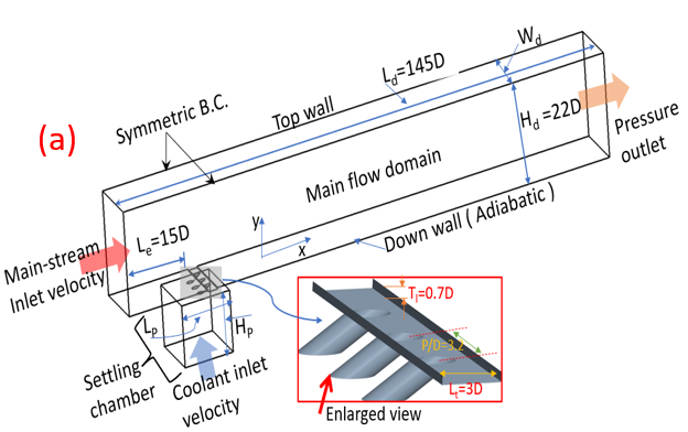
2. Injection Patterns and Flow Region
This study utilizes a carefully designed computational domain to comprehend essential geometry and flow details for precise numerical calculations. The analysis occurs in a three-dimensional computer model (depicted in Figure 1), accurately representing the entire area of interest. A trench is affixed to a cylindrical hole configuration, and this trench is linked to the main flow domain for expelling the coolant into the computational domain. The other end of the injection tube is connected to the settling chamber, where air and mist are blended to form a uniform mixture of the coolant fluid. This arrangement divides the overall flow domain into three distinct zones: the main flow duct, injection tubes, and the settling chamber (outlined in Figure 1). The visualization offers a comprehensive depiction of measurement data, presenting dimensionless values normalized against the injection hole diameter (D), as elucidated further in Table 1. The trench has a height (Ht) of 0.75D from the injection hole opening and a length (Lt) of 3D, as illustrated in Figure 1(a). A schematic diagram, as depicted in Figure 1(b), is provided to offer a geometric understanding of this innovative coolant hole design.
In Figure 1, a single row of three holes, separated by a specified pitch length, maintains a constant inter-hole spacing (pitch = P) of 3.2D. The injection tube's attachment to the main flow domain through an interconnected straight trench introduces an inclination angle (α) of 30◦. By strategically defining a region of interest within the computational domain, demarcated by specific coordinates encompassing Z, the study ensures precision in its analysis.
Table 1: Computational Domain Measurements (Normalized by Hole Diameter)
|
Parameter |
Value |
|
Main Flow Domain Height (Hd) |
22D |
|
Main Domain Length (Ld) |
145D |
|
Main Domain Width (Wd) |
14.2D |
|
Settling Chamber Width (Wp) |
14.2D |
|
Settling Chamber Height (Hp) |
14.2D |
3. Numerical Method and Grid-Independent Test
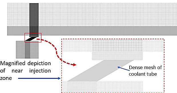
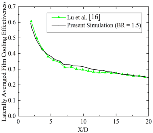
The computational framework implements a three-dimensional steady-state incompressible Reynolds-Averaged Navier-Stokes (RANS) model, integrating the energy equation. By employing the realizable k-ε turbulence model alongside advanced wall treatments, the model demonstrates improved predictive capabilities, particularly in simulating coolant diffusion and boundary layer flow under significant temperature gradients. The selection of the realizable k-ε model is grounded in its close alignment with physical phenomena, ensuring robust and precise flow analysis. The use of a coupled pressure-velocity scheme and a constant pressure base solver ensures computational stability and consistency. A grid sensitivity analysis, as shown in Figure 3(a), confirms mesh independence, with minimal temperature disparities observed among different grid sizes. Consequently, grid no. 3 is chosen for subsequent analyses. The numerical model is rigorously validated under specified conditions, including a mist-free scenario, following the methodology outlined by Lu et al. [16]. Inlet conditions feature a turbulent velocity profile with a 0.6D boundary layer thickness and a Reynolds number of 15,885.
To enhance convergence and stability, a higher-order term relaxation factor of 0.25 is introduced, facilitating accurate numerical simulations conducive to comprehensive fluid dynamics and turbulence analysis. The validity of the study's findings is established through comparative analysis with experimental data from Zhao et al. [15], focusing on cylindrical holes without trenches, although omitted here due to space constraints. Validation against research by Lu et al. [16] further evaluates and contrasts turbulence models' performance in capturing the complex behavior of film cooling processes, as depicted in Figure 3(b).
The model's predictions regarding film cooling effectiveness closely match experimental results obtained over a flat plate, particularly in terms of span-averaged effectiveness (ηav), showing satisfactory agreement with experimental results. There is a slight over-prediction in the zone from X/D = 5 to X/D = 15 in ηav downstream, as shown in Figure 3(b). However, the maximum deviation is less than 5%. This deviation from experimental data may be attributed to the limitations of the turbulence model used for the simulation. Additionally, the interaction of the coolant flow with the sharp edge of the trench generates numerous additional vortices and recirculation zones that can significantly affect the local film cooling effectiveness.
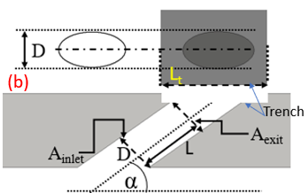
5. Computational Domain and Grid Construction
A cooling arrangement incorporates three linearly aligned single-trenched injection orifices to apply a coolant film on a flat surface. These injection ports have an inlet diameter (D) of 6.35mm, and the injection tube extends to a length (L) of 3D, following the experimental setup of Zhao et al. [15]. Figure 2 provides a close-up view of the meshing around the injection exit, featuring a higher density of mesh nodes near the hole exit for a detailed examination of changes in film performance. In Figure 2, the mesh structure is intentionally reinforced with inflation layers, increasing density near the flat adiabatic surface and the entry points of the film cooling openings. Additionally, specialized edge meshing is introduced to capture crucial flow phenomena governing turbulence and interactions involving water droplets. The hexahedral computational grid, comprising over 6 million cells, was meticulously generated using ICEM-CFD grid generation software for the cylindrical injection scenario. The geometric configuration of the three distinct computational domains, along with detailed meshing around the injection site, is visually depicted in Figure 2. The mesh closely interacts with the region around the trench injection outlet, encompassing the internal injection area where significant changes in fluid flow and heat transfer take place. This grid setup aims to facilitate efficient cooling.
6. Numerical Setup for Turbulence and Governing Equations
The focus of the analysis involves evaluating transport equations for incompressible mass conservation, momentum, and energy. In these assessments, it is reasonable to treat gas properties as constant. Turbulence models are utilized to account for turbulent flows and dissipation. During the interaction between fluid and droplets, significant effects are observed, including the application of drag force on a droplet causing momentum exchange and influencing fluid flow patterns. When employing the discrete phase model (DPM) for particle simulations, the option exists to incorporate these effects. This involves establishing a coupling between Unsteady DPM and steady flow, as discrete particles continuously traverse the system. The analysis, using the Eulerian-Lagrangian (E-L) approach, treats the fluid phase as a continuous medium through the solution of Navier-Stokes equations. Simultaneously, the movement of individual droplets within the calculated flow field is monitored to track the discrete phase. Interactions between dispersed particles, encompassing momentum, mass, and energy exchange with the fluid phase, are considered. A simplification of this approach occurs when particle-particle interactions are disregarded, leading to a more streamlined analysis.
Continuity and Momentum Equations: The numerical resolution of mass and momentum conservation equations is essential for all flows, with an additional focus on energy conservation in cases involving heat transfer. Given the turbulent nature of the flow, additional transport equations are also addressed. The following section outlines the conservation equations specifically tailored for turbulent flow.

Energy Equations: In cases involving heat transfer, an extra energy conservation equation is addressed. Due to the turbulent nature of the flow, additional transport equations are also tackled. This section outlines the conservation equations tailored for turbulent flow in an inertial (non-accelerating) reference frame. Beyond the transport equations governing the continuous phase, a discrete second phase is simulated in a Lagrangian frame. This second phase consists of spherical water droplets dispersed within the continuous phase. The analysis intricately explores the interaction between phases, elucidating its ramifications on both discrete phase trajectories and the dynamics of the continuous phase flow.
Species Transport Equations:
The trajectory of a droplet is predicted by integrating a force balance, comparing the droplet's motion strength to the acting forces, as shown in the following equation:
where FD is the drag force per unit particle mass. CD is drag coefficient for smooth particles. Here, constants a1, a2, and a3 vary based on different Reynolds number ranges, as specified by Morsi and Alexander [17].

The droplet vaporization is simulated to predict the evaporation of a discrete-phase particle. The process initiates when the droplet's temperature reaches the vaporization temperature (Tvap) and continues until the droplet reaches the boiling point (Tbp) or until all easily evaporating components are depleted.
7. Boundary Conditions
Figure 1(a) presents a comprehensive visualization of the computational domain, highlighting two distinct velocity inlets, a single pressure outlet, symmetric walls, and an adiabatic down wall boundary condition. In the main-stream flow domain's initial segment, a prescribed hot-gas velocity is enforced with an input magnitude of 20 m/s, maintaining reference parameter values from prior work [15]. The velocity inlet boundary condition for the coolant (mist-air mixture) is introduced from the bottom of the settling chamber, as illustrated in Figure 1(a), with a specified BR considered as a study variable in this context. A crucial aspect of the study involves maintaining a specific BR at the lower settling chamber face, enabling the precise determination of the coolant-mist input BR. Thus, the momentum is precisely controlled by manipulating the coolant's mass flow rate at the settling chamber inlet. Throughout the investigation, a consistent density ratio of 1.14 and mist droplet diameter of 5µm is maintained across all examined cases, connecting the study with previous research [15] for model reliability. The computational domain is delineated into various zones each with specific boundary conditions. For the hot air inlet zone, the conditions entail a reference temperature of T∞ = 327K. Moving to the Coolant Inlet zone, the BR varies between 0.6 to 1.0 while maintaining a temperature of Tc = 288.30K. Symmetry conditions are applied to the Side Walls zone (as shown in Figure 2), ensuring no alteration in flow across these boundaries. The Other Walls zone is governed by a no-slip condition, indicating that fluid velocity at these walls is nil. Finally, the Outlet zone is defined with a pressure condition set to 1 atm.
8. Results and Discussion
8.1 Effect of Mist Concentration (Mc)
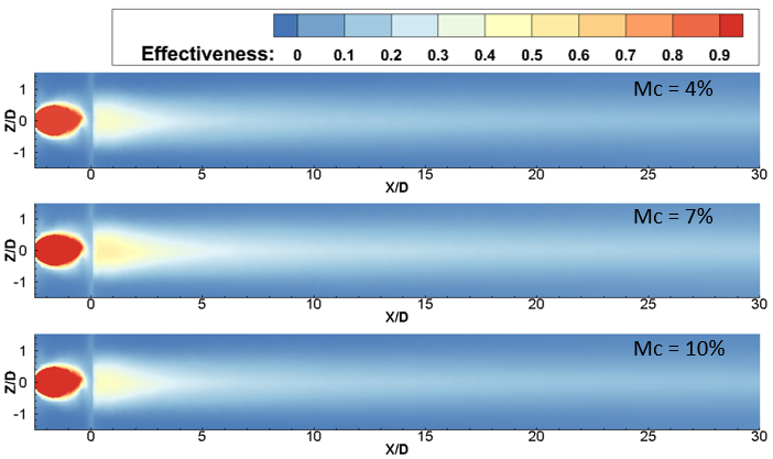
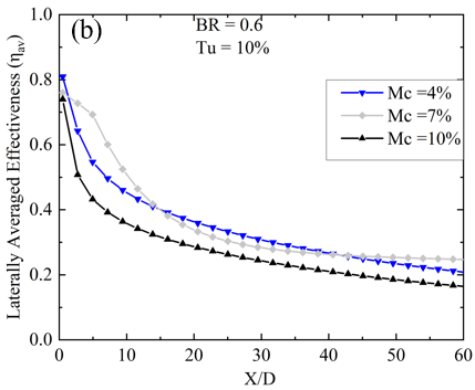
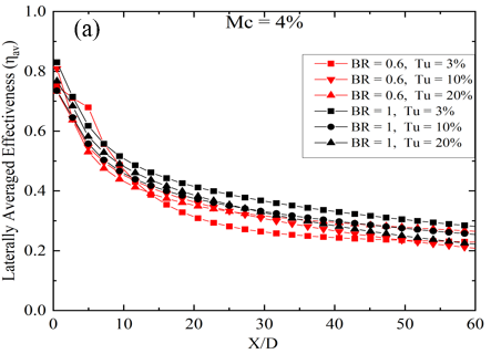
Figures 4 and 5 illustrate the impact of Mist Concentration on spanwise-averaged film effectiveness, correlating with two BR of 0.6 and 1.0. The results are presented against the normalized streamwise distance (X/D) downstream of the film hole's edge at constant turbulent intensity (Tu). The laterally averaged film cooling effectiveness (ηav) is assessed in this study as:
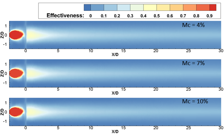
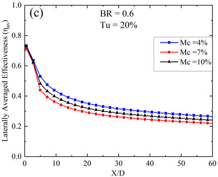
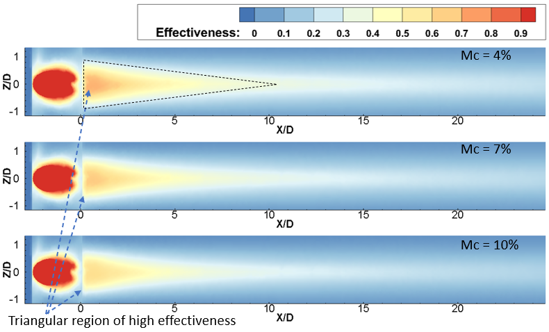
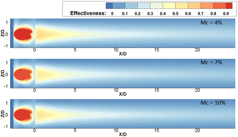
For a lower BR value of 0.6 and a Tu of 3%, the peak ηav occurs at a Mc of 7%. As Tu increases to 10%, a subsequent reduction in ηav becomes evident for the 7% mist concentration case at a streamwise location between 15 < X/D < 40. From Figure 5, it is apparent that with a low Tu of 3% and BR = 0.6, the ηav initially rises as the Mc increases from 4% to 7%. However, beyond a 7% mist concentration, it declines. Additionally, it is noted that at locations near the injection hole, under the same flow conditions (Tu = 3%, BR = 0.6), the laterally averaged effectiveness exhibits marginal disparity, which is less than 5% for each concentration case. This phenomenon can be attributed to the lower mass flow rate of the mist coolant mixture at BR = 0.6. Additionally, the minimal turbulence present prevents the film layer from diffusing into the mainstream hot gas. Consequently, the film remains attached to the surface for an extended X/D length without any disturbance. However, the 10% mist concentration exhibits minimal effectiveness for the remaining portion of the surface away from the injection hole. This could be attributed to the increase in relative humidity with higher Mc’s, which impedes evaporation. Additionally, droplets ejected from the circular section without evaporation possess higher momentum compared to the remaining coolant mixture. As a result, these droplets penetrate the mainstream flow and disperse from the surface without providing substantial cooling effects. The contours of film cooling effectiveness for mass flow ratios BR = 0.6 and Tu = 10% are depicted in Figure 4(b) for various Mc, illustrating how the film covers the vane surface with increased turbulence. Graphical representation is also provided in Figure 5 for the same Tu and BR. It has been observed that from X/D = 3 to X/D = 15, Mc = 7% yields the highest ηav, representing an optimal parametric choice for near injection hole cooling, as highlighted in several previous studies [18,19]. However, within the region between X/D = 15 to X/D = 40, the ηav of Mc = 7% is surpassed by Mc = 4%. The maximum disparity, observed at X/D = 25, is 9% when comparing Mc = 4% and 7%, which may be attributed to the sharp nature of the trench edge. Similar to Tu = 3%, Tu = 20% exhibits a similar degradation trend of ηav with X/D distance, as depicted in Figure 5. However, Mc = 7% yields the lowest ηav compared to other Mc cases. Additionally, contours of film cooling effectiveness at mass flow ratios BR = 0.6 and Tu = 20% are shown in Figure 4(c), where almost no difference is identified between Mc = 4% and 10%. It means that the variation in Mc does not affect the coolant film structure over the surface. Now, at higher Tu of 20% and at BR = 0.6, it has been found that with the increase in Mc from 4% to 7%, the laterally averaged effectiveness decreases. If the Mc is increased further, the ηav gain enhances. The reason behind the enhancement in the case of high Mc is that the availability of water content in the coolant air is comparatively higher, and due to high turbulence intensity, the mist is mixed with hot gas more effectively, causing enhanced evaporation of the mist. Thus, the surrounding temperature is also dropped.
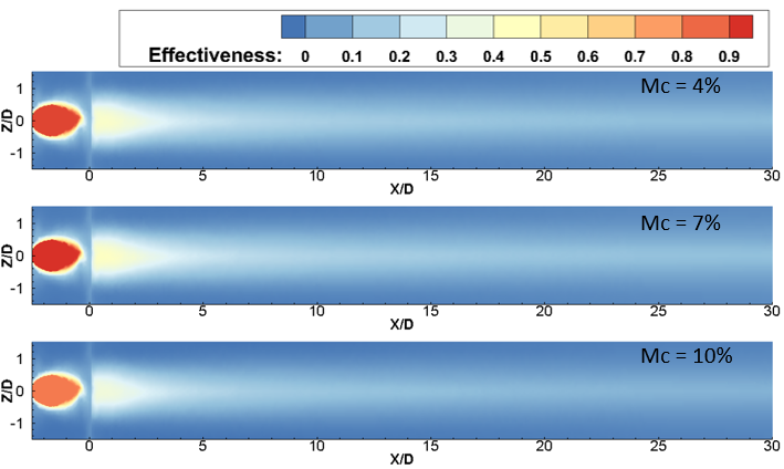
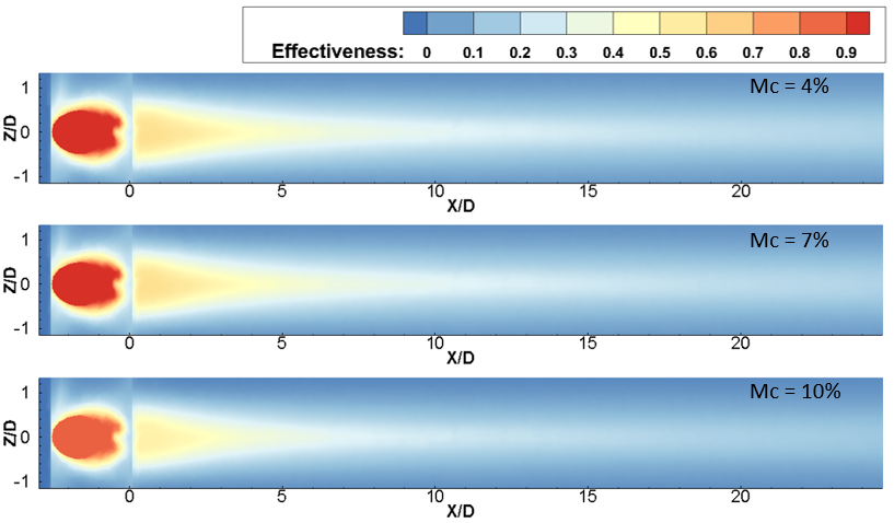
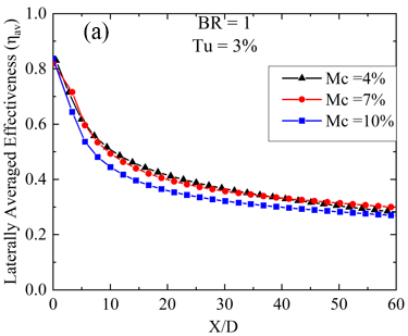
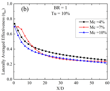
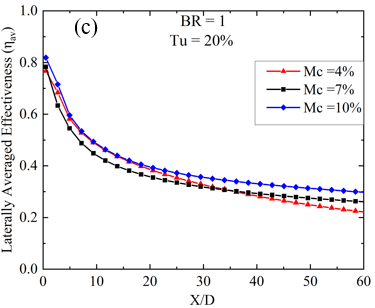
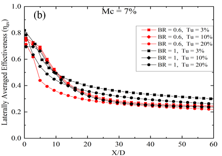
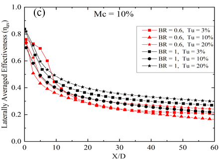
On the other hand, a high BR of 1.0, as depicted in Figures 6 and 7, highlights the influence of Mc on spanwise-averaged film effectiveness analyzed across several Tu. In Figure 6, the effectiveness distribution illustrates an expanded longitudinal spread at BR = 1.0 for each Tu and Mc compared to BR = 0.6. Notably, a long triangular region of higher film cooling effectiveness is easily identifiable in Figure 6 and can be compared to Figure 4 for the BR = 0.6 case. For BR = 1.0 and Tu = 3%, the peak of ηav of mist film (ηav) is observed at a Mc of 7%, near the trench edge. However, there is less than a 5% disparity in the 7% mist content case when compared with an Mc of 4%, and the maximum disparity in magnitude is observed between X/D = 7 to X/d = 25. Further increasing Mc leads to a reduction in ηav, as seen in Figure 7 for Mc = 10% under the same Br = 1.0 and Tu = 3%. As Tu increases to 10% at the same BR of 1.0, a similar trend of higher laterally averaged film cooling effectiveness is observed for the 7% mist concentration case, as previously seen for BR = 0.6 and Tu = 10% for downstream locations between X/D = 0.5 to X/D = 13. However, for the rest of the X/D locations, the effectiveness for Mc = 7% is lower than the 4% case, and in some places, it is even lower than Mc = 10%, as depicted in Figure 5. This indicates that at low Tu of 3% and BR of 1.0, an increase in Mc leads to a reduction in effectiveness at higher BR, similar to BR = 0.6. This observation is also consistent with the Tu = 10% case. However, the lateral spread of the film over the surface at BR = 1.0 remains consistent across all Mc cases, as shown in contour Figure 6; the spreading of the film is wider than the BR = 0.6 case. With the increase of BR, the spreading of the film improves, thus enhancing effectiveness. Moreover, at a higher Tu of 20% and BR = 1.0, it is observed that a higher Mc of 10% provides the highest ηav compared to Mc cases of 4% to 7%. This enhancement with high Mc is attributed to the higher water content in the coolant air, allowing it to travel a greater distance without immediate evaporation at near injection locations. Additionally, due to the high turbulence intensity, the mist is mixed with hot gas more effectively at far downstream locations, leading to enhanced evaporation of the mist.
(a) Tu = 3%
(b) Tu = 10%
(c) Tu = 20%
(a) Tu = 3%
(b) Tu = 10%
(c) Tu = 20%
8.2. Effect of Turbulent Intensity
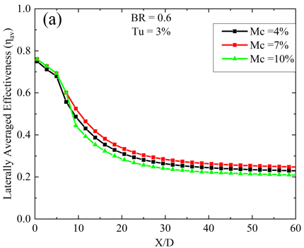
In this section, the impact of turbulent intensity on the film cooling performance of the coolant ejection trench on the flat plate is explored while keeping the mist concentration (Mc) constant for two blowing ratios (BRs) of 0.6 and 1.0. The analysis focuses on the variation in laterally averaged effectiveness, as depicted in Figure 8. Results reveal that at BR = 1.0 and Mc = 4%, the ηav is highest across all X/D locations for Tu = 3%. However, at the same Mc and Tu, lower BR = 0.6 exhibits enhanced lateral film cooling effectiveness within the region spanning from X/D = 4 to X/D = 8, as illustrated in Figure 8(a). The enhanced effectiveness observed at lower BR = 0.6 can be attributed to the formation of cold spots created by non-evaporated mist droplets. These cold spots result in localized areas of high effectiveness [20, 21]. At a low Mc of 4%, the laterally averaged film cooling diminishes up to X/D = 15 with a low BR of 0.6. However, beyond this point (X/D < 15), the ηav exhibits a different trend, being higher for higher Turbulent Intensity (Tu) values of 10% and 20%, and lower for a Tu of 3%. Conversely, at BR = 1.0, the ηav decreases with increasing Tu at Mc = 4%. With a slight increase in Mc, the impact of changing turbulent intensity closely resembles that observed with a 4% mist concentration. Like the 4% mist concentration scenario, there exists a downstream region between X/D = 3 to X/D = 10 where Tu = 3% and 10% result in the highest ηav. Conversely, for the remaining surface area, Tu = 3% at BR = 1.0 demonstrates enhanced ηav compared to all other cases, as shown in Figure 8(b). The only distinction is observed at Tu = 20% and BR = 0.6, where the ηav steeply decreases near the downstream location of X/D < 10. At the highest mist concentration, the variation of Turbulent Intensity (Tu) affects the cooling effectiveness in a slightly different manner. Here, the ηav is highest for the surface region from x/D = 10 to the end of the plate when BR = 1.0 and Tu = 20%. Additionally, for the region near the trench, a low BR of 0.6 and low Tu of 3% are beneficial, as observed in slightly lower mist concentration cases. However, at Tu = 10% and BR = 0.6, the ηav is lower compared to all other cases. The above discussion leads to the conclusion that for low mist concentration, high BR, and low Tu are optimal for achieving greater ηav. Conversely, for high mist concentration, attaining higher effectiveness requires both high Tu and BR.
8.3. Effect of Blowing Ratio
In this section, the laterally averaged effectiveness and its connection to variations in the BR are examined, specifically focusing on two cases: BR = 0.6 and BR = 1.0. Analysis of Figure 8 distinctly reveals that, at low Mc, an increase in BR enhances ηav. This enhancement is attributed to the increased momentum of the coolant-air mixture, which remains uninterrupted over a long X/D distance due to low Tu, resulting in low mixing and improved film cooling efficiency. However, regions near the trench coolant ejection exhibit a different trend, where lower blowing ratios result in higher effectiveness, particularly dependent on Tu. These regions of elevated effectiveness for low BR are concentrated near the injection hole location due to the establishment of a cold spot from mist accumulation. The low mass flow ratio causes mist droplets to be trapped near the trench downstream surface, further enhancing localized cooling. Interestingly, despite increases in mist concentration, BR = 1.0 consistently demonstrates superior cooling capacity due to its higher mass flow rate, enabling more effective heat transfer, especially away from the trench. Figure 8(c) shows that at a higher turbulence intensity of 20% and BR = 1.0, the lateral performance of the film is superior except in some regions near the injection points. Higher mist concentrations amplify effectiveness at BR = 1.0 because turbulence promotes better coolant mixing with the mainstream flow, enhancing convective heat transfer and film cooling effectiveness. In high turbulent flows, the fluctuating velocity fields significantly alter the trajectories of the droplets, causing them to spread more widely and penetrate deeper into the mainstream, especially for Mc = 10%. Additionally, high turbulence increases the likelihood of droplets interacting with the surface being cooled. This interaction enhances cooling effectiveness as the droplets remain on the surface long enough to evaporate, but it can also disrupt the film if the droplets are swept away too quickly.
8.4. Overall Film Cooling Effectiveness
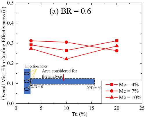
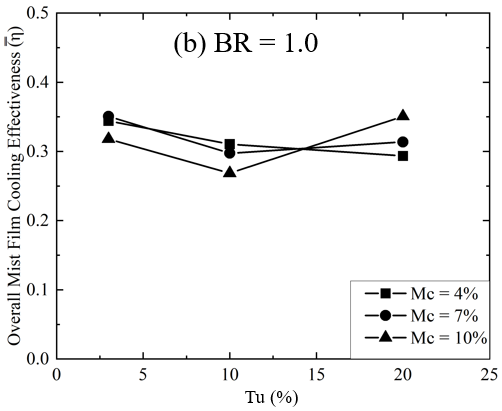
Figure 9 examines
the effect of turbulence intensity (Tu) on the overall mist film cooling
effectiveness ![]() for two blowing ratios, 0.6 and 1.0. The
for two blowing ratios, 0.6 and 1.0. The ![]() is calculated by area-averaging the surface from Z/D=1.5 to Z/D=−1.5 laterally, and from X/D=0 to X/D=60
streamwise, as shown by the black dashed line in Figure 9(a). The analysis
shows that for Mc of 4% and 10%, the
is calculated by area-averaging the surface from Z/D=1.5 to Z/D=−1.5 laterally, and from X/D=0 to X/D=60
streamwise, as shown by the black dashed line in Figure 9(a). The analysis
shows that for Mc of 4% and 10%, the ![]() trend is similar. Initially, the
trend is similar. Initially, the ![]() decreases as Tu increases from 3% to 10%,
indicating that moderate turbulence reduces cooling effectiveness. However, at
Tu=20%, the
decreases as Tu increases from 3% to 10%,
indicating that moderate turbulence reduces cooling effectiveness. However, at
Tu=20%, the ![]() increases, suggesting that higher
turbulence improves mist film cooling, likely due to better mixing and mist
distribution. The highest
increases, suggesting that higher
turbulence improves mist film cooling, likely due to better mixing and mist
distribution. The highest ![]() at BR = 0.6 occurs at Tu=20% with 4% mist
concentration. Conversely, at lower turbulence intensities, a mist
concentration of 7% achieves the highest
at BR = 0.6 occurs at Tu=20% with 4% mist
concentration. Conversely, at lower turbulence intensities, a mist
concentration of 7% achieves the highest ![]() . For BR = 1.0, the
. For BR = 1.0, the ![]() for Mc = 4% and 7% is nearly the same,
with a maximum difference of 7% observed at Tu=20% (see Figure 9(b)). From
Tu=3% to Tu=10%,
for Mc = 4% and 7% is nearly the same,
with a maximum difference of 7% observed at Tu=20% (see Figure 9(b)). From
Tu=3% to Tu=10%, ![]() decreases for all mist concentrations.
However, at Tu=20%, film cooling effectiveness improves, especially for Mc =
10%.
decreases for all mist concentrations.
However, at Tu=20%, film cooling effectiveness improves, especially for Mc =
10%.
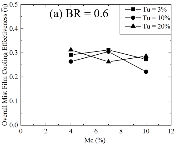
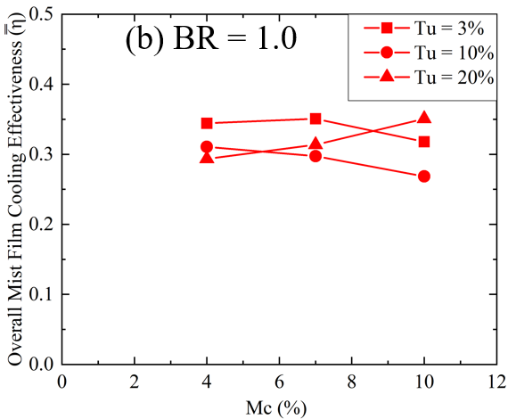
Figure 10
illustrates the variation of ![]() with changes in mist concentration at BR =
0.6 and 1.0. It has been observed that the
with changes in mist concentration at BR =
0.6 and 1.0. It has been observed that the ![]() trend for Tu 3% and 10% is approximately
the same, and at these turbulence intensities, the
trend for Tu 3% and 10% is approximately
the same, and at these turbulence intensities, the ![]() decreases with the increase of Mc for each
BR. However, at Tu = 20%, the
decreases with the increase of Mc for each
BR. However, at Tu = 20%, the ![]() initially decreases with the increase of
Mc and then increases again for BR = 0.6. The highest >
initially decreases with the increase of
Mc and then increases again for BR = 0.6. The highest >![]() at BR = 0.6 is observed for Tu = 3% and
10% at Mc = 7%. At a turbulence intensity of 20%, low mist concentration is
beneficial for BR = 0.6, while high mist concentration is beneficial for
achieving high
at BR = 0.6 is observed for Tu = 3% and
10% at Mc = 7%. At a turbulence intensity of 20%, low mist concentration is
beneficial for BR = 0.6, while high mist concentration is beneficial for
achieving high ![]() at BR = 1.0.
at BR = 1.0.
9. Conclusions
This study is distinctive in exhibiting the stagnation plane flow field with mist-film cooling injection, considering the influence of coolant flow from an upstream slot. The results highlight a significant enhancement in adiabatic effectiveness when film-cooling holes in a trench are coupled with added mist.
- Higher mist concentrations enhance effectiveness due to improved mist evaporation, particularly under elevated turbulence.
- Maintaining constant parameters, the study observes that higher turbulent intensity boosts film cooling effectiveness. Optimal conditions include low turbulence, high BR, and low Mc, emphasizing the delicate balance.
- Higher blowing ratios generally enhance effectiveness, but specific regions near the injection hole favor lower ratios. A consistent superiority of BR = 1.0 is observed, particularly evident at higher mist concentrations.
- Spatially, the examination reveals distinct regions of effectiveness concentration near the injection hole, influenced by mist concentration, Tu, and BR. Optimal conditions for effectiveness vary across mist concentrations, Tu levels, and BR values, providing valuable insights into achieving superior film cooling performance in specific operational scenarios.
- At low BR, overall mist film cooling effectiveness increases slightly with higher mist concentration and low turbulence intensity and remains stable.
- At higher BR, overall mist film cooling effectiveness increases at high Tu with increasing Mc. Higher turbulence enhances the mixing and distribution of the coolant film, improving cooling effectiveness at both BRs.
References
[1] S. Han, R. Zhang, Y. Song, J. Xing, L. Zhou, L. Li, H. Zhang, X. Du, Numerical Study of Swirl Cooling Enhancement by Adding Mist to Air: Effects of Droplet Diameter and Mist Concentration, Appl. Therm. Eng. 211 (2022). View Article
[2] R. Zhang, Y. Song, S. Han, L. Zhou, L. Li, H. Zhang, X. Du, Film Cooling Performance Enhancement of Serrate-Type Trenched Cooling Holes by Injecting Mist into The Cooling Air, Int. J. Therm. Sci. 179 (2022) 1–16. View Article
R. Zhang, S. Han, Y. Song, J. Xing, L. Zhou, L. Li, H. Zhang, X. Du, Evaluation of Mist/Air Film Cooling of C3X Vane with Serrate-Type Trenched Holes, Therm. Sci. Eng. Prog. 33 (2022). View Article
[4] S. Dutta, I. Kaur, P. Singh, Review of Film Cooling in Gas Turbines with an Emphasis on Additive Manufacturing-Based Design Evolutions, Energies. 15 (2022). https://doi.org/10.3390/en15196968. View Article
[5] N. Sundaram, K.A. Thole, Film-Cooling Flow fields with Trenched Holes on an Endwall, J. Turbomach. 131 (2008) 041007. View Article
[6] P. Kalghatgi, S. Acharya, Improved Film Cooling Effectiveness with a Round Film Cooling Hole Embedded in a Contoured Crater, J. Turbomach. 137 (2015) 101006. View Article
[7] P. Kalghatgi, Modal Analysis of Inclined Jet Film Cooling Flows with Density Variation, in: 2016: pp. 1–14.
[8] P. Kalghatgi, S. Acharya, Modal Analysis of Inclined Film Cooling Jet Flow, J. Turbomach. 136 (2014) 081007. https://doi.org/10.1115/1.4026374. View Article
[9] J.H. Kim, K.Y. Kim, Film-Cooling Performance of Converged-Inlet Hole Shapes, Int. J. Therm. Sci. 124 (2018). View Article
[10] H.H. Cho, D.H. Rhee, B.G. Kim, Enhancement of Film Cooling Performance Using a Shaped Film Cooling Hole with Compound Angle Injection, JSME Int. Journal, Ser. B Fluids Therm. Eng. 44 (2001) 99–110. View Article
R.P. Schroeder, K.A. Thole, Effect of High Freestream Turbulence on Flow fields of Shaped Film Cooling Holes, J. Turbomach. 138 (2016) 1–10. View Article
[12] R.P. Schroeder, K.A. Thole, Effect of High Freestream Turbulence on Flow fields of Shaped Film Cooling Holes, J. Turbomach. 138 (2016) 1–10. View Article
[13] R.S. Bunker, K.L. Harrison, D.G. Bogard, J.R. Dorrington, J.E. Dees, Turbine Airfoil Net Heat Flux Reduction with Cylindrical Holes Embedded in a Transverse Trench, J. Turbomach. 131 (2008) 011012. View Article
[14] A. Hasan, K. A. Al-Sallal, H. Alnoman, Y. Rashid and S. Abdelbaqi. Effect of Phase Change Materials (PCMs) Integrated into a Concrete Block on Heat Gain Prevention in a Hot Climate. Sustainability 2016, 8(10), 1009. View Article
[14] Baheri, S., Tabrizi, S.P.A. & Jubran, B.A. Film Cooling Effectiveness from Trenched Shaped and Compound Holes. Heat Mass Transfer 44, 989–998 (2008). View Article
[15] L. Zhao, T. Wang, An Experimental Study of Mist/ Air Film Cooling on A Flat Plate with Application to Gas Turbine Airfoils -Part I: Heat Transfer, J. Turbomach. 136 (2014) 1–9. View Article
[16] Y. Lu, A. Dhungel, S. V. Ekkad, R.S. Bunker, Film Cooling Measurements for Cratered Cylindrical Inclined Holes, J. Turbomach. 131 (2008) 011005. View Article
[17] S.A. Morsi, A.J. Alexander, An Investigation of Particle Trajectories in Two-Phase Flow Systems, J. Fluid Mech. 55 (1972) 193–208. View Article
[18] R. Ragab, T. Wang, An Experimental Study of Mist/Air Film Cooling with Fan-Shaped Holes on an Extended Flat Plate-Part 1: Heat Transfer, J. Heat Transfer. (2017). View Article
[19] T.S. Dhanasekaran, T. Wang, Numerical Model Validation and Prediction of Mist/Steam Cooling in A 180-Degree Bend Tube, Int. J. Heat Mass Transf. 55 (2012) 3818–3828. View Article
[20] X. Li, J.L. Gaddis, T. Wang, Mist/Steam Cooling by A Row of Impinging Jets, Int. J. Heat Mass Transf. 46 (2003) 2279–2290. View Article
[21] T. Wang, X. Li, Mist Film Cooling Simulation at Gas Turbine Operating Conditions, Int. J. Heat Mass Transf. 51 (2008) 5305–5317. View Article