Journal of Fluid Flow, Heat and Mass Transfer (JFFHMT)
ISSN: 2368-6111

Volume 11 - Year 2024 - Pages 187-196
DOI: 10.11159/jffhmt.2024.019
Pressure Drop and Heat Transfer Characteristics in a Microchannel with Pin-Fins
Alişan Gönül1,2, Tassos G. Karayiannis2
1Department of Mechanical Engineering, Siirt University
Kezer Yerleşkesi Veysel Karani Mah. Üniversite Cad. No:1 56100, Siirt, Türkiye
alisan.gonul@siirt.edu.tr;
2Department of Mechanical and Aerospace Engineering, Brunel University London
Kingston Lane, Uxbridge, Middlesex, UB8 3PH, London, United Kingdom
alisan.gonul@brunel.ac.uk; tassos.karayiannis@brunel.ac.uk
Abstract - Pin-fin heat sinks are now considered one of the possible solutions for the thermal management of small-scale devices requiring high heat dissipation rates. Pin-fins with fixed diameters, different heights and spacing were numerically investigated in the current study for a range of Re=200-1000. The micro-channel cross-section with pins at the bottom surface measures 55 mm in length and has a cross-sectional area of 1 mm x 1 mm. The fin height ranges from 0.2 to 0.8 mm and the distance between pin-fins ranges from 3-6 mm. The fins had a circular cross section 0.25 mm in diameter. The Box-Behknen method was used to determine the number of numerical runs based on the parametric range of pin height and spacing and the Re number. Input data and corresponding outputs were presented using the Genetic Aggregation Response Surface Methodology. An optimum pin height and spacing in terms of heat transfer rates was obtained. It has been observed that at the optimum design, considering the highest Performance Evaluation Criteria (PEC) value the microchannel with pin-fins, can provide an enhancement of 364% in heat transfer rates compared to the microchannel without pins, while the corresponding increase in pressure drop reaches up to 162%. Correlations are proposed for heat transfer and pressure drop calculations able to predict the numerical results mostly within 10%.
Keywords: Microchannel, pin-fin, genetic algorithm, heat transfer enhancement, response surface methodology
© Copyright 2024 Authors - This is an Open Access article published under the Creative Commons Attribution License terms Creative Commons Attribution License terms. Unrestricted use, distribution, and reproduction in any medium are permitted, Pr ovided the original work is Pr operly cited.
Date Received: 2024-02-06
Date Revised: 2024-05-27
Date Accepted: 2024-06-04
Date Published: 2024-07-15
1. Introduction
Recent developments in manufacturing technology in electronic components have led to a dramatic increase in power requirements and as a consequence, in required heat flux dissipation rates. This heat transfer bottle-neck could be the leading cause of diminished performance, permanent failure and a hindrance to further developments. It stimulated research in cooling methods to meet this increasing thermal management demand [1]. Micro-channel heat sinks have received a great deal of attention from researchers due to their extremely high surface area/volume ratio, low thermal resistance between the fluid and the substrate to be cooled, and the possibility of a uniform substrate temperature [2]. The resulting high heat transfer rates possible with micro-channel heat exchanges from small surface areas available means that they can be used in a range of applications such as cooling of electronic components, automotive air conditioning, chemical, and biological reactors and fuel-cells, [3]. Therefore, it is now necessary to encourage industrial use of these small to micro-scale heat exchangers by analysing, optimizing and reporting their hydraulic and thermal performance, including possible designs for enhancing heat transfer rates. The use of pin-fins is viewed as one of the most advantageous methods for enhancing the thermal behaviour of these systems. These structures are characterised by micro-pin-fins located at the surface of the microchannel in contact with the substrate to be cooled. Larger convective heat transfer area, secondary fluid flow, eddy generation, and thinner boundary layers result in these geometries outperforming conventional microchannels [1]. A number of studies have been performed to document the effect of different pin fin shapes on heat transfer enhancement.
Yang et al. [4] investigated the heat transfer performance of microchannel heat sinks with circular, square, pentagonal, hexagonal, and triangular pin-fin configurations using deionized water as a coolant. The circular type of pin-fin offered the lowest pressure drop. However, the researchers concluded that the hexagonal section pin fins offered the lowest thermal resistance and were the most suitable of all evaluated designs. Izci et al. [5] investigated numerically single micro pin-fin geometries with the same chord thickness/diameter and reported on their heat transfer and hydraulic performance for Re number ranging between 20 to 120. The working fluid was water. The researchers concluded that the heat transfer rates of fins with sharply pointed regions were superior, i.e. the thermal performances increased by 80% compared to empty channels. Kosar and Peles [6] performed a parametric experimental study on circular, hydrofoil, rectangular and cone pin-fins for a Re range of 14-170 for deionized water. The authors noted that cone-type pin-fins outperformed other designs but only at moderate Re numbers.
Tabatabaei Malazi et al.[7] investigated heat transfer behaviour of rectangular microchannels with circular pin-fins. The other parameters were spacing-to-fin diameter ratios (2, 4, and 6) and five Re values (50, 75, 100, 125, and 150) for a constant fin height-to-channel height ratio of 0.25. They found that the thermal performance of the heat sink could be augmented by up to 23% by adding pin-fins in the microchannel.
Vasilev et al. [8] studied numerically various microchannels having circular pin-fins for Re of 100-1000. Two different pin diameters (0.25 and 0.5 mm), three different spacing (1.5, 3.0 and 6.0 mm) and 5 different heights (0.1, 0.25, 0.4 and 0.5 mm) were considered in the study. They concluded that heat transfer rates and pressure drop are directly related to the fin height. The researchers noted that both heat transfer and pressure drop increased with increasing fin height.
The Response Surface Methodology (RSM) is a statistical approach that allows the assessment of a number of input parameters and one or more response variables. RSM offers ease of estimation and application, particularly in situations where available knowledge on the underlying processes is limited. Therefore, this approach is a useful method to assess available data and to find optimum conditions in several thermal engineering areas. In recent years, RSM methods have been performed to determine and optimize performance in thermal energy storage [9], heat sinks [10], heat exchangers [11]–[13], and micro-channel [3] applications.
In the current research, the effect of varying height and distance of pin-fins placed in a microchannel on the flow and heat transfer rates were studied numerically for different Re numbers. The Box-Behknen design of experiment methods was used to determine the number of numerical runs and study the effect of pin-fin height and longitudinal distance. The data were analysed using the Genetic Aggregation Response Surface Methodology (GARS) to determine the effect of pin-fin height and spacing. The numerical results were analysed and correlations predicting Nusselt number and friction factor in a microchannel with micro-pin fins of different height and spacing are proposed.
2. Numerical runs
2.1 Test Section and Boundary Conditions
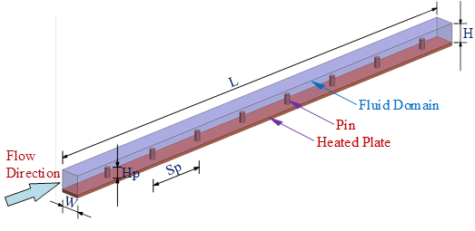
The geometry considered is presented in Figure 1. The microchannel with pin-fins has a cross-section measuring 1 mm x 1 mm (Dh=1 mm) and a length of 55 mm. The diameter of the pin fins is fixed at 0.25 millimetres, while the pin height and distance between pins were used as independent variables.
The microchannel and the pin-fins are made of copper and water was chosen as the working fluid. Table 1 provides a summary of the thermophysical properties, which were assumed constant for the range of this study.
Table 1. Thermophysical properties of Fluid and Solid Materials
|
|
Water |
Copper |
|
k (W.m-1K-1) |
0.6 |
401 |
|
ρ (kg.m-3) |
1000 |
8978 |
|
cp (J.kg-1K-1) |
4182 |
381 |
|
μ (kg.m-1s-1) |
0.001003 |
- |
Fluid flow and energy equations were used to calculate flow parameters, pressure drop and single-phase convective heat transfer using the Laminar model in the ANSYS-Fluent software. The flow domain of the considered geometry is illustrated in Figure 2. Two sections were added before and after the flow domain to help provide appropriate boundary conditions and generate realistic and easily reproducible results for the inlet and outlet effects. The inlet region length was 5Dh, i.e. 5 mm, while the outlet region had a length of 20Dh, i.e. 20 mm. These sections were assumed to be adiabatic.
The input velocity ranged from 0.2 to 1 m/s. At the section outlet, i.e. at the end of the 20 mm adiabatic section, the pressure was set at 0.0 Pa. The no-slip boundary condition was applied to all test section walls. A constant heat flux of 100 kW/m2 was applied from the bottom wall of the heated test section. The heat flux distribution at the bottom of the 0.25 mm heated plate was then assumed to be uniform, see Figures 1 and 2. The fluid temperature inlet was 27 oC. The side walls and the top of the channel wall were assumed to be adiabatic. Studies were carried out for Re=200-1000, Hp=0.2-0.8, and Sp=3.0-6.0.
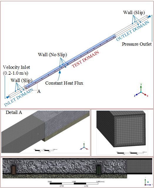
Figure 2 demonstrates the mesh density used for the solution. The optimal mesh structure was reached by applying hexagon and prism mesh types in the entrance and exit domains. Tetrahedron, pyramid, and prism meshes were also applied in the test region. The results of an analysis of mesh independence are shown in Table 2. The table shows values of Nu number and friction factor obtained at Hp = 0.5 mm, Sp = 3mm, and V =1 m/s. As seen in Table 2, the variation of Nu and f results is quite small after the 3 million mesh size and hence this size was selected for this study.
Table 2. Mesh Independency Results
|
Mesh Number |
Nu |
f |
|
496512 |
26.35 |
0.0512 |
|
1362728 |
31.66 |
0.0462 |
|
3379626 |
31.42 |
0.0453 |
|
10123452 |
31.40 |
0.0451 |
2.2 Data Reduction
The parameters that were used to evaluate the results are presented below. The Reynolds number is determined as:

where Dh is the hydraulic diameter and is calculated as follows:

An essential measure of heat transfer performance is the dimensionless mean Nu, which is defined as follows:

h is the average heat transfer coefficient, which is calculated as follows:

Q, Ah, and ΔT indicate the applied heat transfer rate at the bottom surface of the heated wall of the test section, the heat transfer surface area Ah = 1x55 mm2 and the average temperature difference, respectively. The average temperature difference is given by eq. 5 below.
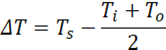
Ts denotes the average temperature at the top of bottom channel test surface. This temperature is calculated after solving the conjugate heat transfer equation based on the constant heat flux applied to the bottom of the 0.25 mm thick substrate. The average fluid temperature (Ti+To)/2 is used here as also in [4] and [5]. Using the logarithmic mean temperature difference gives only a marginal change in the DT and Nusselt number (less than ± 1% in the Nu number).
The formula for the friction factor is given in eq. 6 below.
The Performance Evaluation Criterion (PEC) is used here to define the thermal-hydraulic performance of the heat exchanger [3]. The PEC number is given by eq. 7 as the ratio of the performance of the microchannel with pin fins to that without pin fins.
3. Validation
Computational runs were first performed with different Reynolds numbers in the channel geometry without fins to help validate the numerical method and the mesh size used. The Nu and the friction factor obtained from these runs are compared with well-established correlations, i.e. the Shah and London [14], Lee and Garimella [15], Jiang et al. [16] predicting the Nusselt number in ducts heated from the bottom wall, and side walls. The friction factor results were compared with the Shah and London [14] and Copeland [17] correlations. The comparisons are depicted in Figure 3.
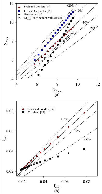
(a) Tu = 3%
As seen in the figure, the current heat transfer results for an empty channel, heated from the bottom and its sides with the top being adiabatic, are in good agreement with all correlations, especially with the Shah and London correlation [14], i.e. the Nusselt number was within 5% in this case. The difference in Nu for a channel heated only at the bottom and heated on three sides as was determined to be below 9% when comparing our results with [14]. The Copeland correlation of the friction factor [17] predicted lower values when compared with our results. However, the agreement with the Shah and London correlation [14] is excellent being within 5%. Based on the above, we concluded that the numerical methodology adopted is appropriate.
The Response Surface Method is used in the present study to develop the mathematical approach to be used for compatibility and sensitivity. For this purpose, the initial step is to implement a suitable Design Of Experiment (DOE) method for the mathematical background and sensitivity analysis [11]. The primary purpose of the DOE method is to generate a data set to evaluate the input-output interactions of design variables. In this study, the Box-Behnken[18] DOE method is utilized, with input parameter ranges as described in Section 2. This method proposes 13 different numerical runs, considering the lowest, highest and average values of the input parameters and the relevant intervals. The RSM appears to be a very useful technique for determining the effects of all variables on the obtained results. The individual interactions between factors and their interdependencies can be assessed using the RSM method. The Genetic Aggregation Response Surface (GARS) method is regarded as an RSM [19]. The Genetic Aggregation method generates more consistent results than conventional metamodeling due to its capacity to achieve multiple response surface solutions and cross-validation, [20]. The GARS method was implemented using the ANSYS DesignXplorer program and all examined parametric and DOE results. Estimating the values of Nu/Nu0, f/f0, and PEC resulted in coefficients of determination (R2) of 0.987, 0.989, and 0.953, respectively.
4. Results and Discussion
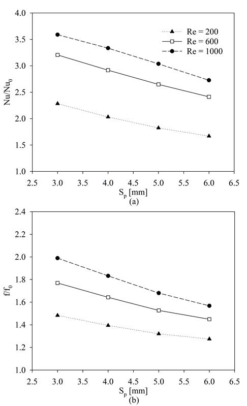
4.1 Effect of fin spacing (Sp) and fin height (Hp) on heat transfer rates and pressure drop.
The effect of varying the fin spacing on the Nusselt number and friction factor is seen in Figure 4 for Re= 200, 600 and 1000. As seen in Figure 4(a), the increase in the Nusselt number with fins compared to the channel without fins increases with Re number.
(a) Tu = 3%
This increase in the absolute (Nu) and relative Nu number (Nu/Nu0) is a strong function of the spacing and decreases with increasing fin spacing. The gradient is fairly constant and the effect is the same for the three Re numbers studied. The friction factor is equally a strong function of the Re number and again decreases with increasing fin spacing. The Nu ratio experiences a growth spanning from 70% to 370% at different Reynolds numbers as the spacing varies. Similarly, the friction factor ratio increases in the range of 30% to 200% with varying spacing.
(a) Tu = 3%
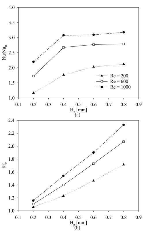
Figure 5 illustrates the variation of Nu/Nu0 and f/f0 with fin height, Hp at different Re numbers. As depicted in the figure, the Nu number increases significantly with fin height at low fin heights. The increase is less pronounced as the height increases, reaching almost constant values at Hp greater than 0.4 mm for Re = 600 and 1000. However, the friction factor, depicted in Figure 5(b) continues to increase for all the Re numbers studied and the entire range of fin heights. It is understood that the increase in the area does not change the rate of heat transfer improvement for increasing Re numbers at increasing fin heights starting from 0.4 mm. According to these results, it can be concluded that the local fluid mixing caused by the pins are more effective in improving heat transfer than the increase in area due to the pins. The Nu ratio exhibits an increase ranging from 10% to 320% as the fin height varies at different Reynolds numbers. Likewise, the friction factor ratio displays an increase in the range of 10% to 230% with varying fin heights.
4.2 Optimised parameter for heat transfer rates and pressure drop
Figure 6 depicts the ratios of (a) Nu/Nu0, (b) f/f0, and (c) PEC numbers for fin heights ranging from 0.2 to 0.8 mm and the variation of fin spacing 3.0 to 6.0 relative to the empty microchannel. The Re number in the figure is 1000. As expected and seen in the figure, the addition of pin-fins generally improves thermal performance at the expense of the pressure drop for the range of fin height, fin spacing and Re studied. The destruction of the thermal boundary layer due to the fins and the subsequent flow patterns after each fin are the primary causes of this effect.
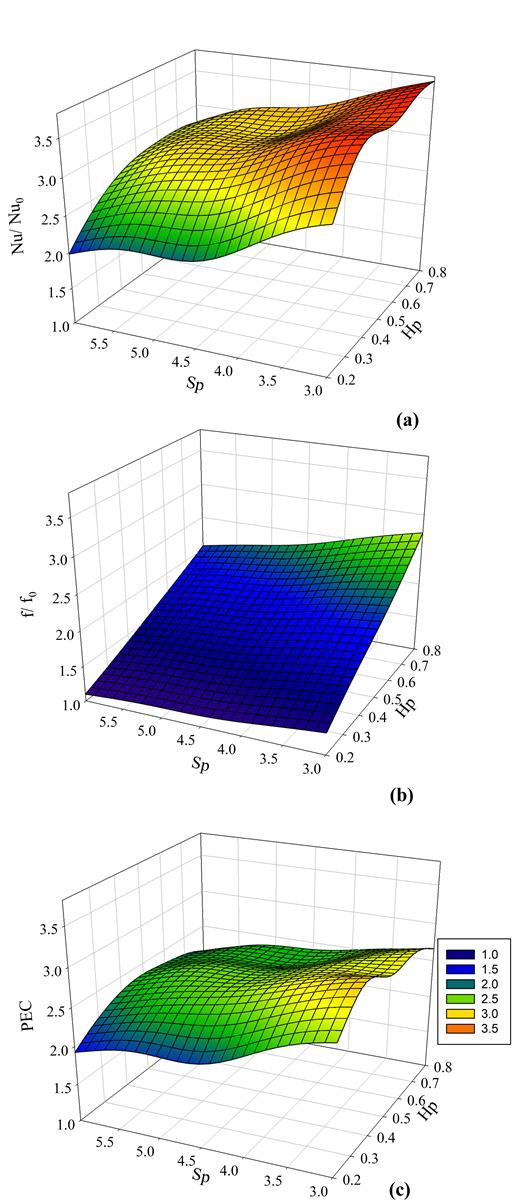
Figure 6(a) demonstrates that the Nu number reaches higher values at high Hp and low Sp values with the dependence on Hp being more pronounced. Generally, the increase in the Nu was found to be between 200% and 367% compared to the empty channel for this Re value. The maximum ratio of Nu/Nu0 is obtained at Hp = 0.4, Sp = 3.0 and Re=1000 according to the results of the GARS methodology. Figure 6(b) depicts the variation of the ratio of f/f0 with changes in Sp and Hp. As seen in the figure, the addition of pin fins increases the f value by 10% to 270% with the increase being higher for Hp values greater than 0.5 and Sp values less than 4.0. The increase in friction depends more on the changes in fin height, rather than fin spacing. Figure 6(c) illustrates the influence of changes in fin spacing and height on PEC. As seen in Figure 5 the friction factor increases linearly with height across all ranges. However, the rate of increase with fin spacing is not constant, see Figure 4. This results in the PEC number reaching its maximum of 3.1 at Hp=0.4. For higher fin heights the rate of increase in the pressure drop was greater than the increase in the heat transfer rate. Therefore, the PEC tends to decrease with height. According to the graph, the optimal PEC value lies between Hp = 0.4 and Sp = 3.0. In addition, Sp = 3 and Hp = 0.4 and Re = 1000 give the best results for the PEC number. The Nu number and friction factor increase by 367% and 178% respectively for this PEC values for these configurations and Re, respectively according to the RSM results.
The numerical analysis is performed at Hp =0.4, Sp = 3.0 mm and Re = 1000 to validate the RSM results at the optimum values of the parameters. It is determined that the results are very close to the RSM results, i.e. the Nu augments up to 364%, f increases up to 162% and the optimum PEC value is 3.10.
5. Correlations
Nu number and f-factor correlations are proposed based on the numerical data obtained with these parametric studies and are given in Equations 8 and 9 respectively.
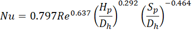
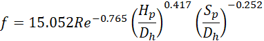
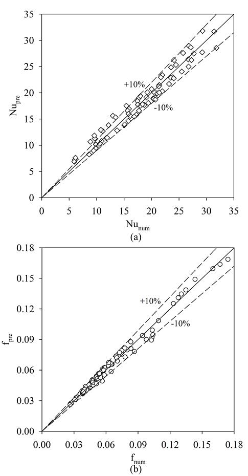
The proposed correlations are valid for the ranges 200 ≤ Re ≤ 1000, 3.0 ≤ Sp/Dh ≤ 6.0, and 0.2 ≤ Hp/Dh ≤ 0.8 and circular cross section fins. The coefficient of determination (R2) is 0.96 for Nu and 0.99 for the friction factor, respectively. Figure 7 depicts the comparison between the numerical and predicted Nu number (a) and friction factor (b) given by equations 8 and 9 above. Both Nu and f correlations are in agreement with the numerical results, i.e. within ±10%. Hence the correlations given here can be an effective tool in predicting heat transfer rates and pressure drop in a microchannel with micro-pin fins.
4. Conclusions
A numerical study was carried out and presented in this paper on the effect of pin fins, located at the bottom of a microchannel of flow cross-sectional area 1 x 1 mm2. The fin pin height was varied from 0.2 to 0.8 mm and the spacing from 3 to 6 mm. The fins were circular with a diameter of 0.25 mm. The Reynold numbers studied were 200, 600 and 1000. The heat flux applied to the bottom wall of the channel was 100 kW/m2. All other walls were assumed to be adiabatic. The results were analysed using the Genetic Aggregation Response Surface Methodology to help find an optimum pin fin height and spacing.
The Performance Evaluation Criterion reached up to 3.10 for the geometry and range of Re number studied. The optimum value of fin spacing and fin height was 3.0 mm and 0.4 mm at Re = 1000 with reference to the highest possible PEC. The Nu and f values at these values are higher by 364% and 162% respectively than the empty microchannel at the same flow rate and geometric conditions. It can also be concluded that the GARS method is a highly advantageous technique for analysing pin-fin applications in microchannels and optimizing the geometrical parameters with respect to improved heat transfer rates and corresponding pressure drop. Finally, Nu number and friction factor correlations are recommended that can be used in predicting the heat transfer rates and pressure drop in these geometries for the range of Re number studied, i.e. up to Re=1000.
Nomenclature
Acknowledgment
Alişan Gönül acknowledges support through the TÜBİTAK BİDEB (2219 Programme) for this one-year fellowship for postdoctoral studies at Brunel University London. The research described in this paper relates to a grant to Brunel University London by the Engineering and Physical Sciences Research Council of the UK (EP/T033045). Thanks are also due to Dr. Ali H. Al-Zaidi for his valuable comments on the draft copy of the paper.
References
[1] P. Bhandari, K. S. Rawat, Y. K. Prajapati, D. Padalia, L. Ranakoti, and T. Singh, "Design modifications in micro pin fin configuration of microchannel heat sink for single phase liquid flow: A review," J. Energy Storage, vol. 66, no. March, p. 107548, 2023, doi: 10.1016/j.est.2023.107548. View Article
[2] T. G. Karayiannis and M. M. Mahmoud, "Flow boiling in microchannels: Fundamentals and applications," Appl. Therm. Eng., vol. 115, pp. 1372-1397, 2017, doi: 10.1016/j.applthermaleng.2016.08.063. View Article
[3] A. Gönül, A. Okbaz, N. Kayaci, and A. Selim Dalkilic, "Flow optimization in a microchannel with vortex generators using genetic algorithm," Appl. Therm. Eng., vol. 201, no. September 2021, 2022, doi: 10.1016/j.applthermaleng.2021.117738. View Article
[4] D. Yang, Y. Wang, G. Ding, Z. Jin, J. Zhao, and G. Wang, "Numerical and experimental analysis of cooling performance of single-phase array microchannel heat sinks with different pin-fin configurations," Appl. Therm. Eng., vol. 112, pp. 1547-1556, 2017, doi: 10.1016/j.applthermaleng.2016.08.211. View Article
[5] T. Izci, M. Koz, and A. Koşar, "The effect of micro pin-fin shape on thermal and hydraulic performance of micro pin-fin heat sinks," Heat Transf. Eng., vol. 36, no. 17, pp. 1447-1457, 2015, doi: 10.1080/01457632.2015.1010921. View Article
[6] A. Kosar and Y. Peles, "TCPT-2006-096.R2: Micro Scale pin fin Heat Sinks -Parametric Performance Evaluation Study," IEEE Trans. Components Packag. Technol., vol. 30, no. 4, pp. 855-865, Dec. 2007, doi: 10.1109/TCAPT.2007.906334. View Article
[7] M. Tabatabaei Malazi, K. Kaya, and A. S. Dalkılıç, "A computational case study on the thermal performance of a rectangular microchannel having circular pin-fins," Case Stud. Therm. Eng., vol. 49, no. May, p. 103111, 2023, doi: 10.1016/j.csite.2023.103111. View Article
[8] M. P. Vasilev, R. S. Abiev, and R. Kumar, "Effect of circular pin-fins geometry and their arrangement on heat transfer performance for laminar flow in microchannel heat sink," Int. J. Therm. Sci., vol. 170, no. September 2020, p. 107177, 2021, doi: 10.1016/j.ijthermalsci.2021.107177. View Article
[9] J. Wołoszyn, "Global sensitivity analysis of borehole thermal energy storage efficiency on the heat exchanger arrangement," Energy Convers. Manag., vol. 166, no. March, pp. 106-119, 2018, doi: 10.1016/j.enconman.2018.04.009. View Article
[10] K. Park, P. K. Oh, and H. J. Lim, "The application of the CFD and Kriging method to an optimization of heat sink," Int. J. Heat Mass Transf., 2006, doi: 10.1016/j.ijheatmasstransfer.2006.03.009. View Article
[11] A. Gönül and Ö. Ağra, "Investigation of heat transfer in tandem and staggered arrangement of wires on single layer wire-on-tube condensers in cross-flow," Int. J. Heat Mass Transf., vol. 158, 2020, doi: 10.1016/j.ijheatmasstransfer.2020.119923. View Article
[12] J. Wen, K. Li, X. Zhang, C. Wang, S. Wang, and J. Tu, "Optimization investigation on configuration parameters of serrated fin in plate-fin heat exchanger based on fluid structure interaction analysis," Int. J. Heat Mass Transf., vol. 119, pp. 282-294, 2017, doi: 10.1016/j.ijheatmasstransfer.2017.11.058. View Article
[13] S. M. Kirkar, A. Gönül, A. Celen, and A. S. Dalkilic, "Multi-Objective Optimization of Single-Phase Flow Heat Transfer Characteristics in Corrugated Tubes," Int. J. Therm. Sci., vol. 186, no. December 2022, 2023, doi: 10.1016/j.ijthermalsci.2022.108119. View Article
[14] R. K. Shah and A. L. London, Laminar Flow Forced Convection in ducts, Supplement 1 to Advances in Heat Transfer. New York: Academic Press, 1978. View Article
[14] S. Baheri, S.P.A. Tabrizi, B.A. Jubran, Film cooling effectiveness from trenched shaped and compound holes, Heat Mass Transf. Und Stoffuebertragung. 44 (2008) 989-998. View Article
[15] P. S. Lee and S. V. Garimella, "Thermally developing flow and heat transfer in rectangular microchannels of different aspect ratios," Int. J. Heat Mass Transf., vol. 49, no. 17-18, pp. 3060-3067, 2006, doi: 10.1016/j.ijheatmasstransfer.2006.02.011. View Article
[16] P. X. Jiang, M. H. Fan, G. S. Si, and Z. P. Ren, "Thermal-hydraulic performance of small scale micro-channel and porous-media heat-exchangers," Int. J. Heat Mass Transf., vol. 44, no. 5, pp. 1039-1051, 2001, doi: 10.1016/S0017-9310(00)00169-1. View Article
[17] D. Copeland, "Optimization of parallel plate heatsinks for forced convection," Annu. IEEE Semicond. Therm. Meas. Manag. Symp., pp. 266-272, 2000, doi: 10.1109/stherm.2000.837093. View Article
[18] G. E. P. Box and D. W. Behnken, "Some New Three Level Designs for the Study of Quantitative Variables," Technometrics, vol. 2, no. 4, pp. 455-475, 1960, doi: 10.1080/00401706.1960.10489912. View Article
[19] ANSYS DesignXplorer User's Guide. ANSYS Inc., 2011.
[20] S. Wang, G. Jian, J. Xiao, J. Wen, and Z. Zhang, "Optimization investigation on configuration parameters of spiral-wound heat exchanger using Genetic Aggregation response surface and Multi-Objective Genetic Algorithm," Appl. Therm. Eng., 2017, doi: 10.1016/j.applthermaleng.2017.03.100. View Article