Journal of Fluid Flow, Heat and Mass Transfer (JFFHMT)
ISSN: 2368-6111

Volume 11 - Year 2024 - Pages 158-167
DOI: 10.11159/jffhmt.2024.016
Enhancing Air Conditioning Performance in Hot Climates through Salt Hydrate PCM-based Latent Heat Thermal Energy Storage: A Numerical Investigation
Mahmoud Haggag1,*, Usman Masood2, Ahmed Hassan3, Mohammad Laghari4
1UAE University, Al Ain, UAE, *Correspondence: mhaggag@uaeu.ac.ae
2UAE University, Al Ain, UAE, 700040271@uaeu.ac.ae
3UAE University, Al Ain, UAE, Ahmed.Hassan@uaeu.ac.ae
4UAE University, Al Ain, UAE, mslaghari@uaeu.ac.ae
Abstract - The cooling of lightweight buildings in extremely hot climate regions poses a significant challenge for the future. As major energy consumers, air conditioning (AC) systems present an opportunity for substantial energy savings through even minor improvements in their performance. This numerical study investigates the use of latent heat thermal energy storage (LHTES) to improve air conditioning performance in hot conditions. LHTES aims to reduce buildings' excessive cooling or heating demands by utilizing phase change materials (PCMs). Specifically, this evaluates the performance for pre-cooling the supply air in AC systems using two types of PCMs salt hydrate (CaCl2.6H2O) with a melting range of 27.7 °C –32.23°C and RT-31 with a melting range of 29°C -33°C. Four designs of an AC duct containing enclosures of PCM have been modelled and simulated using ANSYS/Fluent at different inlet air velocities. The study investigates the impact of incorporating PCM enclosures in the AC duct on the outlet air temperature and the system's maximum coefficient of performance (COPmax). The findings reveal that the PCM-based air-pre-cooling model effectively reduces peak cooling demand, improves the COPmax, and achieves an 8.2°C drop in the supply air temperature at a velocity of 1 m/s in the case of CaCl2.6H2O with design 1 and 7.2°C drop in supply air using RT-31 as PCM. The results suggest that PCM-based LHTES systems are a promising technology for enhancing AC performance in hot environments, leading to significant energy savings and improved thermal comfort in buildings.
Keywords: Phase change material (PCM), Salt hydrate, Air pre-cooling, Air-conditioning, Latent heat thermal energy storage (LHTES), thermal energy storage (TES), maximum coefficient of performance (COPmax).
© Copyright 2024 Authors - This is an Open Access article published under the Creative Commons Attribution License terms Creative Commons Attribution License terms. Unrestricted use, distribution, and reproduction in any medium are permitted, Pr ovided the original work is Pr operly cited.
Date Received: 2023-10-15
Date Revised: 2024-05-22
Date Accepted: 2024-05-30
Date Published: 2024-07-02
1. Introduction
The long-term viability of conventional energy sources, particularly fossil fuels, is under scrutiny due to their detrimental impact on the environment, specifically the release of greenhouse gas emissions [1]. In response to this pressing issue, the Paris Agreement was established to curb global CO2 emissions by 45% from 2010 levels by 2030 and ultimately achieve carbon neutrality by 2050 [2]. Cities account for 80% of the world’s total product and are responsible for 70% of all energy-related CO2 emissions [3-4]. This issue is further exacerbated by the rapid pace of urbanization, posing a growing environmental threat. The stark contrast in air pollution levels between urban and rural areas highlights the severity of this problem, with urban air pollution contributing to 6.5 million premature deaths worldwide [5-6]. This alarming statistic underscores the urgent need for sustainable energy solutions to protect public health and the environment.
Buildings are significant in global energy consumption, accounting for approximately 25% to 30% of the total energy used worldwide [7-8]. This substantial consumption generates considerable carbon emissions, projected to increase to nearly 50% in the next three decades [7-8]. This alarming trend highlights the urgent need to enhance and reduce the load of buildings. A significant portion of energy usage in buildings, approximately 75%, is attributed to space heating and cooling in single-family and multi-family homes [9]. This surge in energy demand necessitates implementing effective energy-saving measures [10]. Among these measures, using TES holds considerable promise in reducing peak-time energy demand [11-13].
The remarkable ability of PCMs, a state-of-the-art material, can store considerable thermal energy [14]. This unique property allows for enhanced thermal stability in buildings. Consequently, integrating PCMs into building envelopes has captured the attention of researchers worldwide, as it holds immense potential for improving indoor thermal comfort and energy conservation [15]. Comparable to building envelopes optimized with PCM, PCM storage systems may be smoothly included in HVAC, air conditioning, and ventilation systems. This makes it possible for the evaporator or condenser to store thermal energy effectively, eventually improving the temperature within the space.
As a result, PCMs have found widespread application in diverse fields and established themselves as environmentally friendly energy-saving materials [16, 17]. Using PCMs in building equipment facilitates precise air temperature regulation, leading to enhanced indoor thermal comfort and a marked improvement in energy efficiency [18]. This remarkable ability to store and release thermal energy makes PCMs a promising solution for addressing the growing energy demands of modern buildings while ensuring occupant comfort and environmental sustainability.
TES has become an essential technology for building demand control [19]. TES provides many attractive advantages, such as notable energy savings and efficient reduction of supply-demand imbalances [20]. PCMs are well known for their variety of uses in architectural structures. These applications include bricks, wallboards, facade components, floors, ceilings, roofs, and glass. Their reversible properties and lightweight characteristics make them well-suited for various applications [21-24].
Several studies have looked at different aspects of PCMs, including how to choose and encapsulate PCMs in hot climates and synthesize and manufacture encapsulated PCMs [27]. Heat transfer augmentation of PCMs can make them more efficient in reducing the thermal load of buildings [28-29]. PCM integration into AC ducts in extremely hot climates is still being explored. This study provides insight by analyzing temperature reduction and the impact on COP by incorporating different PCMs into AC duct systems.
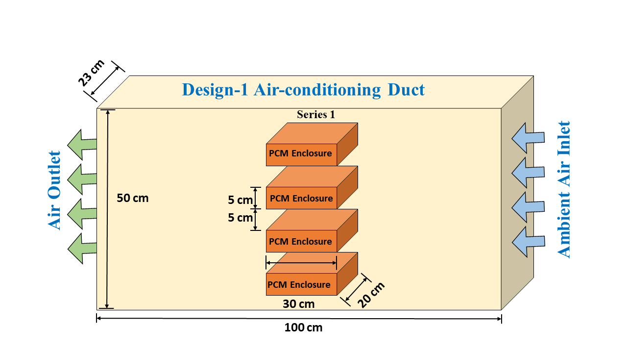
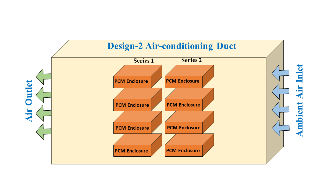
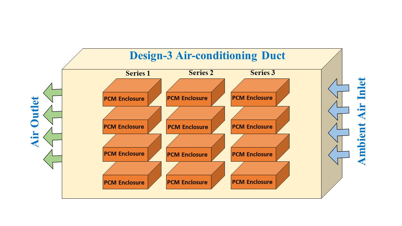
This numerical study investigates PCM based on the air-pre-cooling system. The PCMs will provide a cooler air supply to the evaporator unit. However, selecting the criteria of the PCM plays an essential role in ensuring effective heat transfer and reducing cooling load. The performance of the salt hydrate (CaCl2.6H2O) and paraffin (RT-31) have been compared. Daytime ambient heat flows through the TES unit, enabling the proposed system to function. The process involves cooling the air and subsequently directing it towards the evaporator. Four duct designs from one to four series of columns of PCM containers have been modeled. Air inlet velocity impacts the melting and solidification rates of the PCM and the air exit temperature, potentially leading to energy savings. The ANSYS software is used to create and solve a thorough mathematical model that depicts the physical system.
The data obtained from the numerical simulations has been utilized to calculate the COP of the air conditioning system, which serves as the critical parameter to evaluate the impact of incorporating PCM enclosures within the AC duct system. The COP, a crucial metric for assessing the energy efficiency of cooling systems, provides valuable insights into the potential benefits of integrating PCM-based LHTES with conventional AC systems. By analyzing the variation in COP under different operating conditions and configurations, this study aims to quantify the enhancements in system performance and identify the optimal design parameters for maximizing energy savings and improving thermal comfort in hot climatic regions.
2. Methodology
3. 1. Description of the Experimental Setup
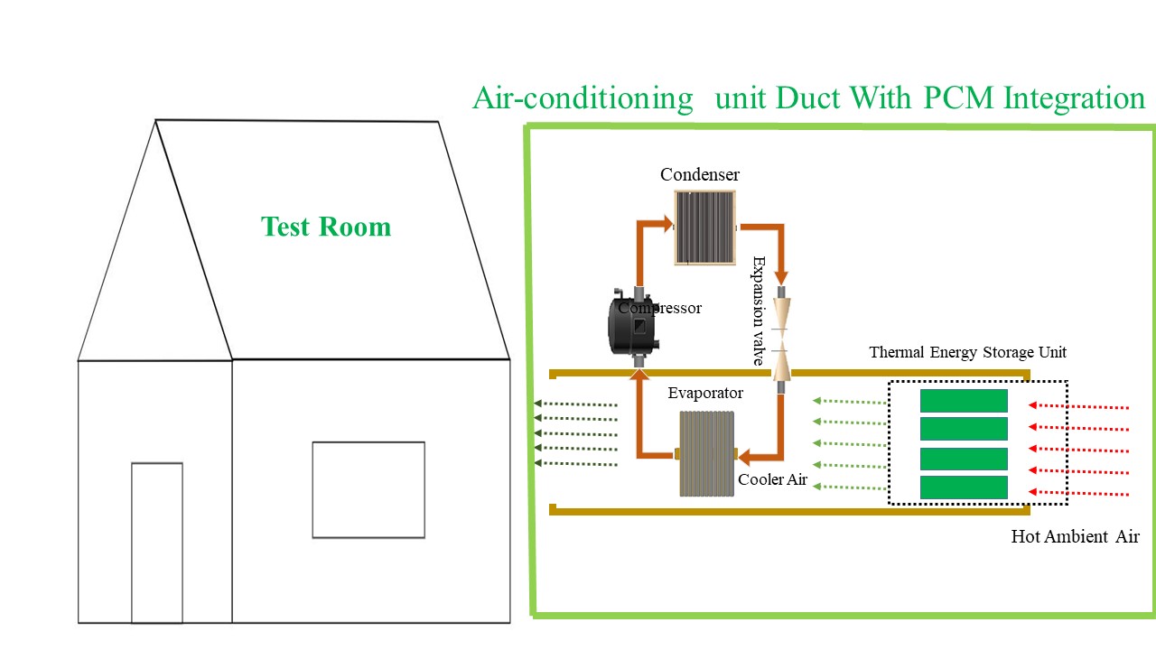
The study aims to make energy-efficient buildings by incorporating TES into air-conditioning ducts. Figure 1 shows the schematic diagram of the study, where hot air enters the AC duct where the TES unit is embedded. The TES unit cools the ambient air before supplying it to the AC evaporator, which further cools the air and supplies it to the building.
This study evaluated the modelling and simulation of the AC duct contacting one series of salt hydrates as a PCM. This quantifies the cooling effect and the duration of PCM melting.
2.1. Weather Data Analysis
The main purpose of installing a pre-cooling unit is to lower energy usage and maintain high thermal comfort. PCMs are essential for keeping indoor temperatures stable. To achieve these goals, several design factors need to be considered, such as ambient temperature, humidity levels, airspeed, and the specific cooling needs of the residential building. Finding a balance between these design considerations and reducing energy consumption is crucial. Maintaining stable indoor air temperatures and providing long-lasting thermal comfort are also important [4].
The main purpose of installing a pre-cooling unit is to lower energy usage and maintain high thermal comfort. PCMs are essential for keeping indoor temperatures stable. To achieve these goals, several design factors need to be considered, such as ambient temperature, humidity levels, airspeed, and the specific cooling needs of the residential building. Finding a balance between these design considerations and reducing energy consumption is crucial. Maintaining stable indoor air temperatures and providing long-lasting thermal comfort are also important [4].
2.2. Material Analysis
Selection criteria for PCMs necessitate excluding materials designed for higher temperature ranges. A PCM with a melting temperature range of 27–33°C was deemed suitable for this air pre-cooling application. Among the available options, inorganic salt hydrates were identified as the most promising PCMs due to their desirable characteristics of high TES capacity and an appropriate melting point within the specified range.
A few degrees above the morning air temperature was used to determine the melting range. Consequently, a PCM with a melting point between 27.7 °C and 32.23 °C was chosen. Inorganic salt hydrates were selected due to their desirable properties of high TES capacity and a suitable melting range.
2.2. Material Analysis
The selection of an appropriate PCM requires careful consideration of various physical, chemical, economic, and thermal properties [5, 11]. Salt hydrates offer favorable properties for PCM applications compared to the RT-31 in heat transfer.
- Thermal conductivity is approximately 0.6 W/m.K
- Heat of fusion is around 210 kJ/kg
- Density is approximately 1.6 kg/m³
- These properties make salt hydrates promising candidates for a variety of PCM applications.
These properties make salt hydrates promising candidates for a variety of PCM applications.
Table 1: Thermo-physical properties of CaCl2.6H2O and RT-31.
|
Properties |
CaCl2.6H2O |
RT-31 |
|
Density-(kg/L) |
1.5 |
1.6 |
|
Melting Point-(°C) |
27.7-32.23 |
29-33 |
|
Specific Heat Capacity-(kJ/kg·K) |
2 |
2 |
|
Latent Heat-(kJ/kg) |
213.66 |
246 |
|
Heat Conductivity-(W/m·K) |
0.6 |
0.3 |
3. Numerical Model
Using the finite-volume approach, a two-dimensional heat transfer model for four different designs of PCM enclosures placed in an air duct has been created. This model treats the PCM as an incompressible fluid inside the computational domain while the material melts. This simplified mode ignores minor effects like buoyancy-induced movement of solid dendrites inside the molten PCM, spontaneous convection within the PCM, and volume changes after a phase transition (Figures 2, 3, 4, 5).

The differential equation (1) governs the transient heat transport in two dimensions [30]. Heat flux (q), which stands for incident irradiance, is applied at the surface as a boundary condition.
where xi and xj are unit vectors, ρ is density, c is heat capacity, k is thermal conductivity, T is temperature, and t is time. Conduction in the domain is taken into consideration by equation (1), which ignores boundary heat losses. Equations (2) and (3) specify the heat losses are applied at the boundary:


The convective and radiative heat losses are denoted by Zc and Zr , respectively, and the convective heat loss coefficient is hc. The container area is represented by A, the emissivity by ε, the Stefan–Boltzman constant by σ, the ambient temperature, by Tamb, and the sky temperature by T∞. Equation (4) is the result of applying heat losses to the unified governing equation of heat transmission.
The weak formulation, denoted by equation (5), is obtained by doubling the test function δT and integrating it across the domain.
Equation (8) is the consequence of simplifying the weak formulation in part 2 of Equation (6) by using the Green–Gauss and divergence theorems.
Equation (7) provides a weak 2D transient differential heat diffusion formulation that maintains the energy balance.

The variables in the equation are ![]() , which represents the irradiance or boundary flux matrix,
, which represents the irradiance or boundary flux matrix, ![]() which represents the time derivative of temperature; and M, K, H, and R, which represent the matrices for mass, conductivity, convection, and radiation respectively. The Crank–Nicholson approach discretizes the domain temporally [31, 32]. Equation (8) indicates how to model the heat storage during a phase shift using the effective heat capacity approach [33]:
which represents the time derivative of temperature; and M, K, H, and R, which represent the matrices for mass, conductivity, convection, and radiation respectively. The Crank–Nicholson approach discretizes the domain temporally [31, 32]. Equation (8) indicates how to model the heat storage during a phase shift using the effective heat capacity approach [33]:
 or else
4. Result and Discussion
This study evaluates the performance of a TES system integrated into an air conditioning (AC) duct comprising four different PCM enclosure designs. The assessment involves monitoring critical parameters, including outlet air temperature, average PCM temperature, melting time, and the AC system's COP. The performance assessment of the suggested system is conducted by examining different input air velocities, specifically 1 m/s to 4 m/s. The inlet air temperature is adjusted to 45°C, representing the average daytime temperature observed in regions with extremely hot climatic conditions.
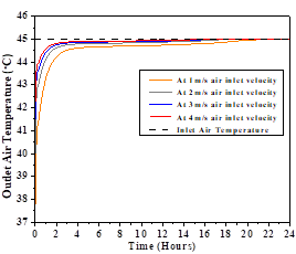
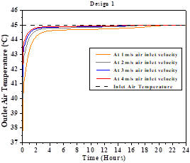
The findings indicate the 24-hour evaluation of the output air temperature while using CaCl2.6H2O as a PCM. Figure 6 depicts the impact of various air inlet velocities on the PCM enclosures' duct system. The PCM based duct designs enclosures of the duct system led to a reduction in the outlet air temperature below the inlet air temperature. At an air velocity of 1m/s to 4m/s, the temperature drop was reported to be approximately 8.2°C, 5°C, 3.6°C, and 3°C respectively. While using paraffin-RT-31 at air velocity of 1m/s to 4m/s, the temperature drop was approximately 7°C, 5°C, 3.4°C, and 2.8°C (Figure 7). This temperature reduction is attributed to the heat transfer from the passing air to the PCM. The proposed designs incorporating PCMs offer a substantial advantage in regions where the ambient air temperature remains around 45°C for 2-3 hours during the peak daytime hours. By utilizing these PCM-based systems, a significant decrease in the outlet air temperature can be achieved, consequently reducing the overall cooling load requirements. This, in turn, can improve the COP of the air conditioning system, reducing the installed capacity and ultimately resulting in energy savings.
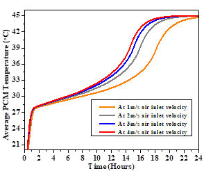
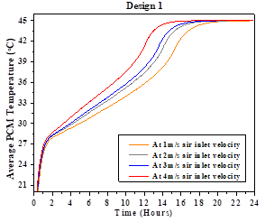
Figure 8 illustrates the average PCM temperatures at different air velocities using CaCl2.6H2O. From 20°C - 27.7°C, sensible heat storage is the most prevalent in the PCM, while latent heat storage is the most prevalent from 27.7°C - 32.5°C. After the PCM has fully transitioned to its liquid state, the TES mechanism shifts back to sensible heat storage within the temperature range of 32.55°C - 45°C. Similar trends in average temperature have been observed when using RT-31 as PCM (Figure 9). Due to the higher heat transfer capacity of CaCl2.6H2O, the temperature gradient becomes small as with containers of the outlet air, and it takes more time to melt as compared to RT-31. As the airflow rate increases, the temperature gradient within the PCM becomes more pronounced, leading to a faster attainment of the reference temperature compared to lower air velocity scenarios. Figure 10 illustrates the maximum temperature reduction achieved at four distinct air flow rates.
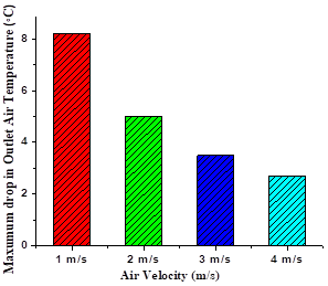
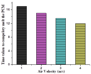
Figure 11 displays the PCM melting time. At an air velocity of 1 m/s, it took PCM about 17 hours to completely melt, 15 hours for 2 m/s, 13.8 hours for 3 m/s, and 12.5 hours for 4 m/s.
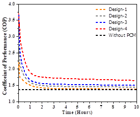
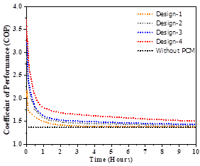
Figure 7 and 8 show the results of the theoretical COP of an air conditioning system when the inlet air was pre-cooled using two different PCMs and when the inlet air was not cooled. These results provide valuable insights into the potential performance enhancement of incorporating PCM-based pre-cooling techniques in air conditioning systems. Pre-cooling the inlet air using PCMs can significantly reduce the thermal load on the air conditioning system, thereby reducing energy consumption and improving overall efficiency. The theoretical COP values presented represent the theoretical maximum efficiency. The COP is calculated using the equation (9) [34]. where Troom is the desired room temperature, which is considered 26 °C, and Toutside is the outside ambient temperature.

The results show that the theoretical COP values are higher when the inlet air is pre-cooled using PCMs than when it is not. The duct design impact indicated that temperature reduction is more significant with more PCM columns achieved. Hence, the COP is better. CaCl2.H2O depicts a better COP than RT-31, attributed to the higher heat transfer coefficient of CaCl2.6H2O.
Furthermore, this improvement in COP can be attributed to the reduced temperature difference between the room and the inlet air, which leads to a lower energy input requirement for the air conditioning system to maintain the desired room temperature. It is important to note that the theoretical COP values obtained serve as upper limits for the actual COP of practical air conditioning systems.
Table 2: Maximum COP calculation using CaCl2.6H2O-based four AC Duct designs at variable air velocity
|
Velocities |
COP-Design-1 |
COP-Design-2 |
COP-Design-3 |
COP-Design-4 |
|
1 m/s |
2.203 |
2.736 |
3.656 |
3.714 |
|
2 m/s |
1.857 |
2.047 |
2.229 |
2.363 |
|
3 m/s |
1.677 |
1.818 |
1.911 |
2 |
|
4 m/s |
1.595 |
1.699 |
1.768 |
1.857 |
Table 2 presents the maximum COP values for an air conditioning system employing air pre-cooling using CaCl2·6H2O as a PCM with four different duct designs and four different air velocities. An analysis of the data reveals several notable observations.
Firstly, the COP values decrease with increasing air velocity for all four duct designs, suggesting that lower air velocities are more favourable for achieving higher system efficiency. Secondly, the duct designs exhibit varying performance levels, with Design 1 consistently exhibiting the lowest COP values across all air velocities, while Design 4 yields the highest COP values, indicating it is the most efficient duct configuration. The maximum COP of 3.714286 is achieved with Design 4 at an air velocity of 1 m/s, representing the most efficient combination of duct design and air velocity.
Furthermore, at low air velocities, such as 1 m/s, the COP values range from 2.20339 (Design 1) to 3.714286 (Design 4), demonstrating a significant impact of duct design on efficiency. However, as the air velocity increases to 4 m/s, the COP values across all designs converge towards a narrower range, from 1.595092 (Design 1) to 1.857143 (Design 4), indicating a reduced influence of duct design on efficiency at higher air velocities.
The results suggest that a combination of Design 4 duct configuration and a low air velocity of 1 m/s should be employed for optimal system performance. When selecting the appropriate duct design and air velocity, practical considerations such as pressure drop, fan power consumption, and heat transfer rates should also be considered. The findings highlight the importance of optimizing duct design and air velocity to achieve maximum efficiency in air conditioning systems utilizing PCM-based pre-cooling, guiding the selection of appropriate parameters for system implementation and further improvement.
Table 3: Maximum COP calculation using RT-31 based four AC Duct designs at a variable air velocity
|
Velocities |
COP-Design-1 |
COP-Design-2 |
COP-Design-3 |
COP-Design-4 |
|
1 m/s |
2.08 |
2.888 |
3.25 |
3.714 |
|
2 m/s |
1.857 |
2.166 |
2.363 |
2.383 |
|
3 m/s |
1.733 |
2 |
2.05 |
2.09 |
|
4 m/s |
1.529 |
1.733 |
1.857 |
1.877 |
The analysis of Table 3, which presents the maximum COP values for an air conditioning system employing pre-cooling of air using RT-31 as a PCM with four different duct designs and four different air velocities, reveals several notable observations. Consistent with the findings of Table 2, the COP values decrease with increasing air velocity for all four duct designs, reinforcing the notion that lower air velocities are more favourable for achieving higher system efficiency when utilizing PCM-based pre-cooling.
Furthermore, the duct designs exhibit varying performance levels, with Design 1 consistently exhibiting the lowest COP values across all air velocities. Design 4 yields the highest COP values, suggesting it is the most efficient duct configuration when using RT-31 as the PCM. The maximum COP of 3.714286 is achieved with Design 4 at an air velocity of 1 m/s, which aligns with the previous table's findings for the optimal combination of duct design and air velocity.
Notably, the COP values in this table are generally lower than those observed in the previous table, which used CaCl2·6H2O as the PCM, highlighting the influence of the chosen PCM material on the overall system efficiency. At low air velocities, such as 1 m/s, the COP values range from 2.08 (Design 1) to 3.714286 (Design 4), demonstrating a significant impact of duct design on efficiency. However, as the air velocity increases to 4 m/s, the COP values across all designs converge towards a narrower range, from 1.529412 (Design 1) to 1.877143 (Design 4), indicating a reduced influence of duct design on efficiency at higher air velocities.
While the results provide valuable insights into the performance of the PCM-based air-pre-cooling system, it is important to acknowledge the potential uncertainties and limitations associated with the findings. The PCM thermophysical properties have been simplified in the simulation by using single values within specific ranges. The numerical modelling approach employed in this study involves several simplifying assumptions and approximations, which may introduce uncertainties in the predicted results. For instance, the assumption of treating the PCM as an incompressible fluid during the phase change process may neglect certain complex phenomena such as buoyancy-induced movement of solid dendrites within the molten PCM, spontaneous convection within the PCM, and volume changes accompanying the phase transition. Additionally, the accuracy of the numerical models, the underlying governing equations, and the quality of the mesh generation and grid independence can influence the simulation results. Furthermore, the boundary conditions and material property values used in the simulations may not accurately represent the real-world scenario, leading to potential discrepancies. Proper validation and verification of the simulation results against experimental data or analytical solutions are crucial to quantifying and mitigating these uncertainties. Nonetheless, the findings provide valuable insights and serve as a foundation for further refinement and optimization of PCM-based air-pre-cooling systems.
The results suggest that for optimal system performance when using RT-31 as the PCM, a combination of Design 4 duct configuration and a low air velocity of 1 m/s should be employed. When selecting the appropriate duct design and air velocity, practical considerations such as pressure drop, fan power consumption, and heat transfer rates should also be considered. The findings further reinforce the importance of optimizing duct design and air velocity while highlighting the influence of the chosen PCM material on the overall system efficiency, guiding the selection of appropriate parameters for system implementation and further improvement.
5. Conclusion
This study investigated integrating an LHTES system using PCMs into an AC duct system for air pre-cooling applications in extremely hot climates. The results demonstrated the potential of the proposed PCM-based design to significantly reduce the temperature of the supply air to the evaporator coil, with maximum temperature drops of 8.2°C, 5°C, 3.6°C, and 3°C observed at variable inlet air velocities of 1m/s to 4m/s, respectively when using CaCl2.6H2O as PCM. While using paraffin-RT-31 at air velocity of 1m/s to 4m/s, the temperature drop was approximately 7°C, 5°C, 3.4°C, and 2.8°. The performance of CaCl2.6H2O is better as it can provide better COP and greater temperature reduction.
The analysis of the theoretical COPmax revealed notable improvements when incorporating the PCM-based pre-cooling system compared to a conventional AC system without pre-cooling. This enhancement in COPmax translates to potential energy savings and increased efficiency in cooling systems operating in hot climates.
The PCM enclosures' melting profiles and cycling stability were also evaluated, indicating their suitability for the target application. Overall, the findings highlight the promising role of PCM-based LHTES systems in enhancing the performance of air conditioning units, leading to reduced energy consumption and improved thermal comfort in buildings in extremely hot climate regions.
References
[1] United Nations Framework Convention on Climate Change. The Paris Agreement. 2015. Available online: https://unfccc.int/process-and-meetings/the-paris-agreement/the-paris-agreement (accessed on 27 January 2019). View Article
[2] Intergovernmental Panel on Climate Change. Global Warming of 1.5 °C. 2016. Available online: https://www.ipcc.ch/sr15/ (accessed on 27 January 2019). View Article
[3] IEA. Energy Technology Perspectives: Towards Sustainable Urban Energy Systems; IEA: Paris, France, 2016; Volume 14.
[4] D.F. Dominković, Modelling Energy Supply of Future Smart Cities; Technical University of Denmark: Kongens, Denmark; Lyngby, Denmark, 2016.
[5] N. Hooftman, L. Oliveira, M. Messagie, T. Coosemans, J. Van Mierlo; Environmental Analysis of Petrol, Diesel and Electric Passenger Cars in a Belgian Urban Setting. Energies 2016, 9, 84. View Article
[6] IEA. Energy and Air Pollution; IEA: Paris, France, 2016.
[7] D. Li, Q. Wang, P. Lin, Y. Chen; Analysis of the Heat-Flux Characteristics of the Turbulent Boundary Layer in the Trombe Wall. J. Energy Eng. 2021, 147, 04021052. View Article
[8] J. Narbuts, R. Vanaga, R. Freimanis, A. Blumberga; Laboratory Testing of Small-Scale Active Solar Façade Module. Environ. Clim. Technol. 2021, 25, 455-466. View Article
[9] J.H. Patel, M. Qureshi, P. Darji; Experimental analysis of thermal energy storage by phase change material system for cooling and heating applications. Mater. Today Proc. 2018, 5, 1490-1500. View Article
[10] Kutty NA, Barakat D, Darsaleh AO, Kim YK. A Systematic Review of Climate Change Implications on Building Energy Consumption: Impacts and Adaptation Measures in Hot Urban Desert Climates. Buildings. 2024; 14(1):13. https://doi.org/10.3390/buildings14010013 View Article
[11] M. Isaac, D. P. van Vuuren; Modeling global residential sector energy demand for heating and air conditioning in the context of climate change. Energy Policy 2009, 37, 507-521. View Article
[12] F. Souayfane, F. Fardoun, P.H. Biwole; Phase change materials (PCM) for cooling applications in buildings: A review. Energy Build. 2016, 129, 396-431. View Article
[13] D. Connolly, H. Lund, B. Mathiesen; Smart Energy Europe: The technical and economic impact of one potential 100% renewable energy scenario for the European Union. Renew. Sustain. Energy Rev. 2016, 60, 1634-1653. View Article
[14] A. Hasan, K. A. Al-Sallal, H. Alnoman, Y. Rashid and S. Abdelbaqi. Effect of Phase Change Materials (PCMs) Integrated into a Concrete Block on Heat Gain Prevention in a Hot Climate. Sustainability 2016, 8(10), 1009. View Article
[15] D.Mao, M. Pani, M.J. Song, Z. Li, S.M. Deng, Operating optimization form proved energy consumption of a TAC system affected by night time thermal loads of building envelopes, Energy, 133 (2017), p. 491-501. View Article
[16] Y. Ma, X. Chu, W. Li, G. Tang, Preparation and characterization of polymethyl methacrylate-co-divinylbenzene) microcapsules containing phase change temperature adjustable binary core materials, Sol. Energy Vol. 86 (2012), p. 2056-2066. View Article
[17] Hasan, A., McCormack, S.J., Huang, M.J. and Norton, B., 2010. Evaluation of phase change materials for thermal regulation enhancement of building integrated photovoltaics. Solar energy, 84(9), pp.1601-1612. View Article
[18] S. Mengjie, N. Fuxin, M. Ning, H. Yanxin and D. Shiming, Review on building energy performance.
[19] Masood, U., Haggag, M., Hassan, A. and Laghari, M., 2023. Evaluation of Phase Change Materials for Pre-Cooling of Supply Air into Air Conditioning Systems in Extremely Hot Climates. Buildings, 14(1), p.95. View Article
[20] Haggag, M., Masood, U., Hassan, A. and Laghari, M., 2024. The Use of Phase Change Materials for Cooling Applications in the Hot Climate of the UAE. Advances in Science and Technology, 137, pp.65-76. View Article
[21] B. Duraković; PCMs in building structure. In PCM-Based Building Envelope Systems: Innovative Energy Solutions for Passive Design; Springer Nature: Cham, Switzerland, 2020; pp. 63-87. View Article
[22] B. Duraković; PCM-based glazing systems and components. In PCM-Based Building Envelope Systems: Innovative Energy Solutions for Passive Design; Springer Nature: Cham, Switzerland, 2020; pp. 89-119. View Article
[23] B. Duraković, S. Mešetović; Thermal performances of glazed energy storage systems with various storage materials: An experimental study. Sustain. Cities Soc. 2019, 45, 422-430. View Article
[24] B. Duraković; PCMs in Separate Heat Storage Modules. In PCM-Based Building Envelope Systems: Innovative Energy Solutions for Passive Design; Springer Nature: Cham, Switzerland, 2020; pp. 121-146. View Article
[25] N. Farhat, Z. Inal; Solar thermal energy storage solutions for building application: State of the art. Herit. Sustain. Dev. 2019, 1, 1-13. View Article
[26] U. Masood, M. Haggag, A. Hassan, and M. Laghari, "A Review of Phase Change Materials as a Heat Storage Medium for Cooling Applications in the Built Environment," Buildings, vol. 13, no. 7, p. 1595, 2023. View Article
[27] Haggag M, Hassan A, Masood U. THE USE OF PHASE CHANGE MATERIAL TO REDUCE PEAK AIRCONDITIONING LOAD IN HOT CLIMATE OF UAE. In Bantanur S, editor, 9th Zero Energy Mass Custom Home International Conference, ZEMCH 2022 - Proceedings. ZEMCH Network. 2022. p. 788-797. (ZEMCH International Conference). View Article
[28] Y. Huang, A. Stonehouse, C. Abeykoon; Encapsulation Methods for Phase Change Materials-A Critical Review. Int. J. Heat Mass Transf. 2023, 200, 123458. View Article
[29] A. Karthikeyan, K.S.Nimay, C.H. Dinesh, J. Jayaprabakar, A. Jacob; Performance Enhancement of Solar Thermal Systems Using Phase Change Materials-A review. Mater. Today Proc. 2023. View Article
[30] Lewis, R.W.; Morgan, K.; Thomas, J.R.; Seetharamu, I.N. The Finite Element Method in Heat Transfer Analysis; John Wiley & Sons: Hoboken, NJ, USA, 1999. [Google Scholar]
[31] Reese, T.G.; Heid, O.; Weisskoff, R.M.; Wedeen, V.J. Reduction of eddy-current-induced distortion in diffusion MRI using a twice-refocused spin echo. Magn. Reson. Med. Off. J. Int. Soc. Magn. Reson. Med. 2003, 49, 177-182. [Google Scholar] [CrossRef] View Article
[32] Bang, D.; Lee, J.H.; Lee, E.S.; Lee, S.; Choi, J.S.; Kim, Y.K.; Cho, B.K.; Koh, J.K.; Won, Y.H.; Kim, N.I.; et al. Epidemiologic and clinical survey of Behcet's disease in Korea: The first multicenter study. J. Korean Med. Sci. 2001, 16, 615-618. [Google Scholar] [CrossRef] View Article
[33] Lamberg, P.; Lehtiniemi, R.; Henell, A.M. Numerical and experimental investigation of melting and freezing processes in phase change material storage. Int. J. Therm. Sci. 2004, 43, 277-287. [Google Scholar] [CrossRef] View Article
[34] Cengel, Yunus A., Michael A. Boles, and Mehmet Kanoğlu. Thermodynamics: an engineering approach. Vol. 5. New York: McGraw-Hill, 2011.}: