Journal of Fluid Flow, Heat and Mass Transfer (JFFHMT)
ISSN: 2368-6111

Volume 11 - Year 2024 - Pages 81-90
DOI: 10.11159/jffhmt.2024.009
Wearable Multistage Thermoelectric Cooler Design and Fabrication
Elisa Y.M. Ang1, Peng Shu Ng 1, Chew Beng Soh1 and Peng Cheng Wang 1
1Engineering Cluster, Singapore Institute of Technology
10 Dover Drive, Singapore 138683 Singapore
Elisa.Ang@singaporetech.edu.sg; PengShu.Ng@singaporetech.edu.sg; ChewBeng.Soh@singaporetech.edu.sg;
Victor.Wang@singaporetech.edu.sg
Abstract - Current commercial off the shelves Thermoelectric coolers (TECs) are commonly used for electronics and they usually require big and bulky heat sinks to dissipate the heat generated. TECs are however attracting attention in recent years to provide localized cooling to humans, potentially reducing energy wastage while providing adequate thermal comfort outdoors. In this work, we show that by optimizing the internal structure of the TEC, namely its fill factor (FF), aspect ratio (AR) of the semi-conductor legs, as well as the number of stages, a thermally efficient TEC that can provide a cooling sensation of up to -10 ℃ can be fabricated without the need for any heatsink. To further investigate its suitability for human comfort, we integrated this TEC to a vest, resulting in a lightweight and ergonomically comfortable cooling vest prototype. This work also presents a quick prototyping methodology with simple laboratory equipment to fabricate the selected TEC for experimental validation.
Keywords: Thermoelectric coolers, thermoelectric coolers prototyping, cooling wearables, thermoelectric, wearable technology, thermally efficient, lightweight
© Copyright 2024 Authors - This is an Open Access article published under the Creative Commons Attribution License terms Creative Commons Attribution License terms. Unrestricted use, distribution, and reproduction in any medium are permitted, provided the original work is properly cited.
Date Received: 2023-11-27
Date Revised: 2024-04-24
Date Accepted: 2024-05-02
Date Published: 2024-05-06
1. Introduction
Although thermoelectric coolers (TECs) based on Peltier effect were realized since 1954(1), there has been no widespread usage for this technology due to its low efficiency. In recent years however, interest in TECs is renewed as scientific research have pushed the efficiency of such devices beyond what was previously achievable (2). Its solid-state, compact properties and the fact that it does not require refrigerant also magnifies its potential in being adapted for wearable thermoregulation devices (3–5). Wearable thermoregulation devices are garnering interest in the scientific community and in the industry as an alternative to traditional cooling strategies. This is due to both the warming climate, and also the realization that traditional cooling strategies often lead to high energy wastage (4) and contributes significantly to global greenhouse gas emissions (6). Traditional cooling strategies such as air conditioning or fan are also not suitable for outdoors environment such as construction sites (4), and this is becoming an increasingly pressing problem with global warming. Cooling wearables provide localized cooling, potentially reducing energy wastage with the capability of providing adequate thermal comfort outdoors. Coupled with advancements in TEC technology, such as discovery and design of high-performance thermoelectric materials (7), there is now immerse interest from the scientific community and industry in the field of TECs wearables.
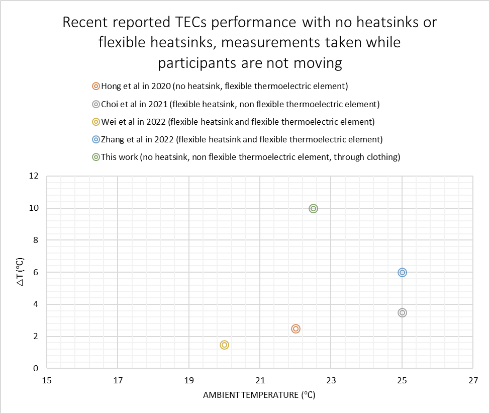
Current TECs that exist in the market are optimized for electronics, and therefore usually have a rigid construction with its structure optimized for low resistive environment (8–10). These commercial TECs currently available are hence not suitable for direct application as wearable thermoregulation devices. Recent literature has highlighted two main changes to be made to adapt current TEC technology for cooling wearables. First, for TECs to be flexible and light, and second, redesigning the internal structure of TEC itself to be efficient for use against human skin. There are many recent works that have proposed different designs for flexible TECs(4, 10–12). This requires TECs and its heat sink to be both made of flexible materials, since the TECs typically cannot achieve sufficient cooling effects without a proper heat sink (3). There are also recent works looking at the integration of passive thermal storage technology to TEC heat sink (13). Choi et al in 2021 presented a flexible TEC made with small TECs embedded in silicone elastomer with flexible heat sink design using ternary composite made of silicone elastomer, phase-change material and graphite powder (3). However, the proposed combination provides only a 3.5 ℃ drop in temperature at ambient temperature of about 25 ℃ . In 2022, Wei et al proposed another design of flexible TEC using thermoelectric (TE) legs with pin-fin soft cover (12). Their design was only able to provide a 1.5 ℃ temperature drop with an ambient temperature of 20 ℃. Also recently in 2022, Zhang et al presented a 2-axis flexible TEC device made of TE legs with two-layer hydrogel-nickel foam heat sink, which was able to attain a 6 ℃ temperature drop with an ambient temperature of 25 ℃ with the participant being still (10). Xu et al used an alternative innovative approach, where the flexible TECs are coupled with a heatsink that uses vortex generators to dissipate heat effectively, achieved about 6 ℃ reduction in temperature when the subject is not moving, at an ambient temperature of 25 ℃ (4). The focus of these recent works is on making TECs flexible while still providing a cooling effect. However, whilst the TECs are flexible and able to generate some cooling effects, the TECs internal structure is far from optimized and often arbitrary. This explains the comparatively small cooling effects reported in these works.
Thus, equally important is the second point of optimizing the TEC internal design itself for use against human skin. Recent literature has pointed to three main parameters of TEC internal design that are drastically different for application on human skin, as compared to electronics. These are the (i) fill factor (FF), which represents the percentage of TEC surface that the TEC legs occupy, (ii) the aspect ratio (AR) which measures the height of the leg with respect to the leg’s width, and (iii) the number of stages. In 2019, Kishore et al used a rigid prototype to prove that TEC with high aspect ratio and low fill factors are optimal for use in high resistive environment, such as against human skin, while the opposite is true for low resistive environment (9). Commercial TECs typically found off the shelves are usually manufactured with fill factor greater than 25% and aspect ratio close to 1. Kishore’s work however found that for use against human skin, a fill factor of less than 20% and aspect ratio closer to 2 is optimal. The team achieved a temperature drop of 8.2 ℃, but with the use of a rigid heatsink, at an ambient temperature of 22 ℃. Hong et al (14) also recognized the need for high aspect ratio and low fill factor, and designed a flexible TEC with an ultrahigh aspect ratio of 5 and an ultralow fill factor of 6.25%, achieving a maximum of 6 ℃ drop against human skin. In 2022, our team built a numerical model and performed a detailed parametric study on the TEC internal structure. The results showed that a 2-stage TECs, with fill factor between 10 and 15 % is ideal for use against skin with a leg aspect ratio of more than 2 (8). Although the numerical model indicates that a larger aspect ratio is ideal, this might compromise the structural integrity of the TE legs. Consulting with TE manufacturers, an aspect ratio of 2.8 is easily obtainable off the shelf. It was also found from the numerical model that the current ratio between the two stages of the TEC should be 0.5 for optimal operation (8). It is however recognized that the numerical model is inaccurate at higher currents due to the underestimation of conduction and convection heat transfer.
In this contribution, we present a simple lab-based fabrication methodology using common lab equipment to realize the physical model of the recommended configuration as found by the numerical model (8). The performance of the lab-based prototype is compared with a factory fabricated prototype of the same design. Through this prototyping methodology, we performed testing to show that by optimizing the internal structure of the TEC, we achieved a 10 ℃ skin temperature drop (∆T) with a current of 0.4A at 22 ℃ ambient temperature, without the need for any heatsink. The achievement of our current work, as compared to those from the literature discussed in the previous two paragraphs, are presented in Fig. 1. In Fig. 1, only TEC performance without any heatsinks, or using only flexible heatsinks, are included. This is because big and bulky heatsinks are not relevant for use as cooling wearables. In addition, it is known that TEC performance is very sensitive to ambient temperature as well as convective cooling on the hot side. Hence, the ambient temperature where the TEC performance is reported is shown in Fig. 1, and only performance measured when the TEC is subjected to minimal forced convection is compared. This means that the participants are usually still and not performing motions such as swinging of arms or walking. It can be seen that our current work has a distinct advantage over current state-of-the-art TECs fabricated for the purpose of cooling wearables. The fabrication procedure and materials used are also largely similar to commercial TECs, hence driving down the cost of the TECs itself as compared to other more complicated fabrication procedures reported in these works (3, 10, 12, 14).
This contribution has two main impacts. First, the fabrication methodology outlined requires no sophisticated equipment and can be realized using commonly found lab equipment. This is important, as it can be difficult to perform experimental validation of thermoelectric technology without specialized lab equipment such as electrodeposition or milling machine or incurring high non-recurring engineering cost to fabricate custom-made TECs in bulk. The simple lab-based fabrication procedure described here allows such prototypes to be achieved easily, further encouraging research efforts in this field. Second, the resulting fabricated TEC achieved a good temperature drop against human skin of 10℃. This is significantly more than previous results achieved without the use of heatsinks with minimal force convection. This is also comparable with performances achieved with state-of-the-art flexible heatsinks. This highlights the importance of optimizing internal parameters of TECs for different usage, and we hope that this work would help guide research in the field of flexible TECs to better optimize its internal structure for use as cooling wearables. Lastly, a vest prototype was fabricated with these custom TECs without heatsinks and the vest was found to be light and non-restrictive even though the TECs are still rigid. The entire vest with 6 TECs incorporated only weighs less than 520g.
2. Simple Procedure for Multi-Staged TEC Fabrication without the Need for Specialized Equipment
To illustrate the low cost required to fabricate the TEC, as well as to ensure repeatability where required, the raw materials and laboratory equipment used to fabricate the TEC reported in this work is detailed in Table 1. The material cost can be driven down when bulk fabrication is considered, instead of the small quantity fabrication we are considering here. However, for a laboratory fabricated prototype, the cost can be considered marginal.
Table 1 Materials required for fabrication of the TEC reported in this work
|
Material |
Quantity |
Cost (USD) |
Supplier |
|
1mm thick Aluminum nitride plate |
3 |
12 |
Zhengzhou Mission Ceramic Products Co., Ltd |
|
0.3 mm thick Copper plates |
1 |
12 |
Lazada store |
|
Soldering paste |
2 |
6.50 |
Shopee store |
|
Nickel Coated Bismuth Telluride legs – precut into required size (1.4 by 1.4 by 4 mm) |
82 P and 82 N legs |
11 |
Ganzhou LuckPr Advanced Materials CO.,Ltd |
|
Thermal tape |
2x 40 by 40 mm |
1.60 |
Shiu Li Technology Co., Ltd. |
|
Sealant |
1 Tube |
3.70 |
TESON Hi-Temp Blue RTV Gasket Maker (100% Silicon Rubber) |
|
Raw material cost required for 1 TEC in lab-based environment |
46.80 |
||
The laboratory equipment required for the fabrication of this reported TEC are all general lab equipment, namely soldering iron, hot plate, tweezers, metal cutters and multicore black and red copper wires. The fabrication procedure is illustrated in Fig. 2.
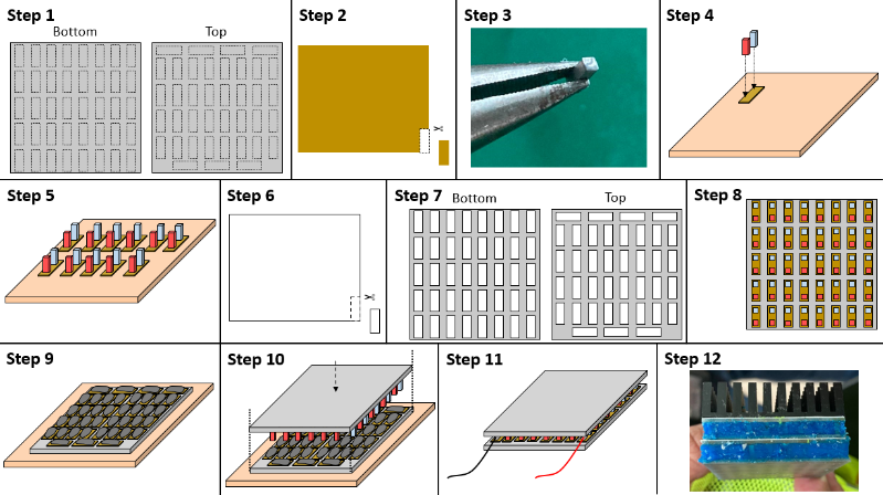
The first step of the process is to trace out the placement of the copper plates onto the AlN ceramic plate. Following which in step 2, copper plates of appropriate sizes would be cut out using straight tin snips. In this design, the copper plates are mostly of a sized 3.5 by 8.5 mm to ensure even placement. Step 3, the p and n bismuth telluride legs are dipped into solder paste. To ensure good and straight attachments, it is essential that only a small amount of solder paste is used in this step. Next, in step 4, the copper plate are placed onto a hot plat that has been preheated to 180 °C, and the p/n legs are placed on the copper plate to allow the solder paste to melt. In step 5, step 4 is repeated for all the copper plates on the bottom plate. When all the copper plates on the bottom plates are done, the hot plate is then turned off to allow the solder paste to solidify. Step 6 requires thermal tapes to be cut to appropriate sizes, similar to copper plates. Next, in step 7, the thermal tapes are pasted onto the AlN ceramic plates in their respective positions. After that is done, the next step, step 8 is to paste the copper plates with P/N legs onto the bottom AlN plate and the empty copper plates onto the top AlN plates. In the assembly step, step 9, the Top AlN plate is first placed onto a hot plate that has been preheated to 180 °C and a generous amount of solder paste is then applied onto the copper plates on this top AIN plate. In Step 10, after the solder paste has melted, align the edges of the bottom plate to the top plate and firmly press down to assemble the TEC. Turn off the hot plate to allow the solder paste to solidify. Once the TEC assembly has cooled down, the next step, step 11 is to solder the wires onto the copper plate using a soldering iron. Lastly, the TEC is sealed off with a high temperature sealant to protect the legs from water or other debris.
The fabricated TEC has a total surface area of 40 by 40mm, fill factor of 10.2%, aspect ratio of 2.8 and has two stages. The weight of each fabricated TEC is about 47g. The current ratio to be applied to this TEC during operation is kept at 0.5, which has been shown to be optimal for use against skin (8). The performance of this TEC is characterized by both experimental and numerical setup, which will be elaborated in the next section.
3. Experimental and Numerical Setup
3.1. Experimental Setup
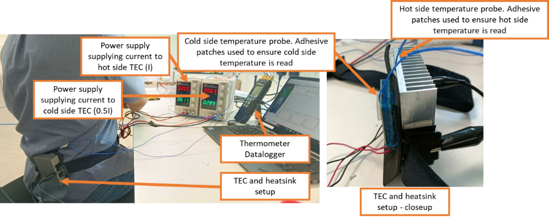
After the TEC is fabricated as detailed in Section 2, two different experiments were set up to characterize its performance. The first experimental setup aims to replicate and validate what was reported in our previous work which was used to characterize the off-the-shelf TECs (single and double stage TEC1-12703) performance against human skin (8). In the reported work, a large aluminum heatsink is used to dissipate heat from the hot side of the TEC and the cold side of the TEC is in contact with the lower back of a human test subject (IRB Application 2021017). Identical setup is used in this work, but now with our own fabricated TEC. In this experiment, there is a layer of clothing between the TEC cold side and the human skin. We have adopted this setup as a separate test has shown that the performance of the TEC and temperature measured are not significantly altered by the layer of cloth. In addition, in cooling wearable especially on human’s torso, it is likely that the TEC would be worn on top of a layer of cloth for hygiene purpose. The cold and hot side temperature on the TEC is measured with a thermocouple (Center 374 Thermometer) in a setup as shown in Fig. 3. Four temperature probes are used, the first and second probes are to measure the hot and cold side temperatures of the TEC (Th and Tc) respectively. These two probes are insulated with adhesive patches to ensure the temperature readings are taken from the relevant sides as shown in Fig. 3. The third probe is used to measure the skin temperature (Ts) of at the torso of the human test subject in an area that is not in the vicinity of the TEC. Therefore, ∆T=Tc-Ts gives a measurement of the cooling sensation that the human test subject feels. The last probe is used to measure the ambient temperature of the surrounding. Constant current is supplied to the top and bottom TEC stages using separate power supplies. To achieve the current ratio of 0.5, the top TEC (closer to the heatsink) will always receive a current twice that of the bottom TEC next to human skin.
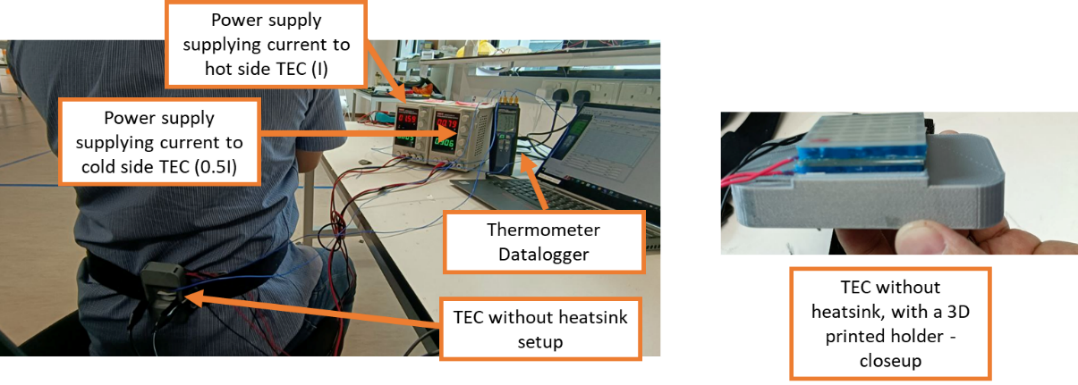
In our second experiment setup, the TEC performance is characterized without attaching any heat sink. To hold the TEC in contact with the human body via a similar setup, a 3D printed holder is designed to fit the TEC to attach it to the waistbelt. This is depicted on Fig. 4.
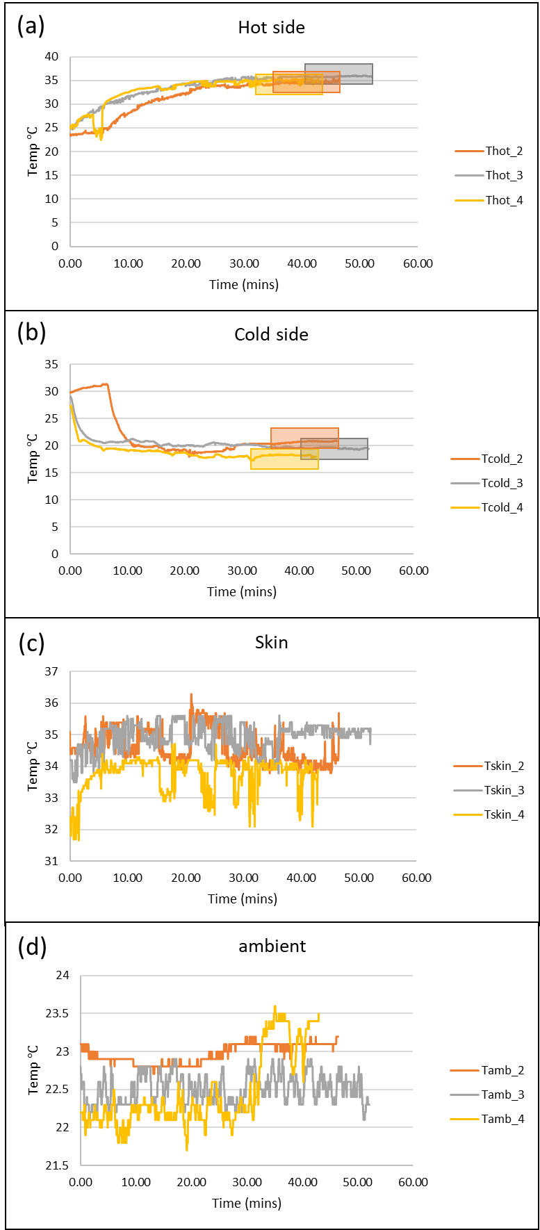
For all the experimental runs, each configuration is repeated at least 3 times, and each experiment is carried out until steady state conditions are reached where the temperatures are no longer changing. The experiment is carried out in indoor conditions regulated by air conditioning, hence, the maximum and minimum ambient temperature recorded was 23.5 ℃ and 21.5 ℃ respectively. A typical measurement results for one experiment is presented in Fig. 5 for a hot side current of 0.6A with aluminum heatsink (experimental setup 1). Four measurements are recorded, namely the hot side, cold side, skin and ambient temperature. The experiment was carried out for 40 to 60 minutes and it can be seen that the temperatures initially were not steady. To obtain the steady state values for comparison across different configurations, the last 10 minutes of the measurements (as shaded in Fig. 5) were averaged out for each run. All the results displayed in Section 4 are therefore the averaged steady state values of each configuration across at least three separate runs, with the standard deviation of the results represented as error bars within the graphs.
3.2. Numerical Setup
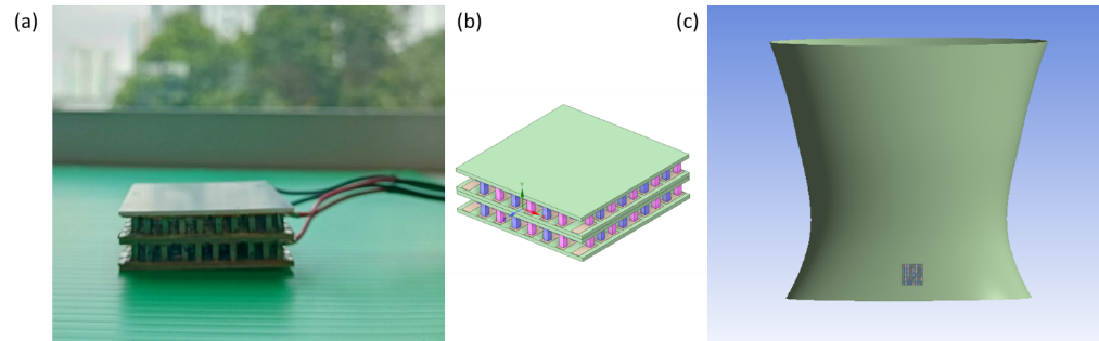
The numerical model that was built in our previous work (8) is implemented here for our fabricated TEC using ANSYS thermal-electric system. The ANSYS model is a complete one that includes modelling of the human body thermoregulatory model as well as the thermal-electric behavior of the TEC. Fig. 6a shows the physical fabricated TEC and Fig. 6b shows the numerical model of our fabricated TEC. The TEC numerical model is placed on the lower back position of the numerical human torso (as shown in Fig. 6c), similar to the experimental setup. The material properties used are identical to that reported in (8) with the exception that for this TEC, the thermal conductivity of the p and n legs are 5 W/mK instead of 1.25 W/mK used. Experimental measurements indicated that these p and n legs that are bought off the shelves have a slightly higher conductivity than that typically used for bismuth telluride in theoretical calculations (9). With the aluminum heat sink, the hot side is assumed to be subjected to a convective coefficient hhs of 40 ![]() , similar to that defined in the previous reported work (8). For the simulation without heat sink, the hot side is assumed to be subjected to a convective coefficient hhs of 5
, similar to that defined in the previous reported work (8). For the simulation without heat sink, the hot side is assumed to be subjected to a convective coefficient hhs of 5 ![]() , representative of natural convection in an indoor setting.
, representative of natural convection in an indoor setting.
4. Results and Discussion
4.1. With Aluminum Heatsink Attached to TEC Hot Side
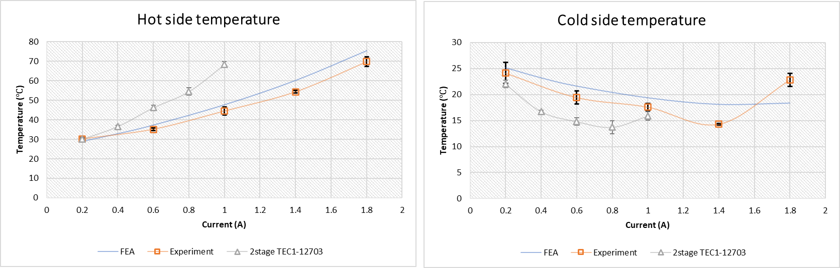
The recorded hot and cold side temperature with varying current for the fabricated TEC in this work is shown in Fig. 7. Together in the same graph, the performance of a 2-stage TEC1-12703 as well as the FEA predictions of the fabricated TEC from this work is presented for comparison. It is to be noted that the current presented in the graphs are the current supplied to the hot side of the TEC (stage 2). The first stage will receive half the current of stage 2 to achieve a current ratio of 0.5.
The first observation is that the hot side temperature of this fabricated TEC is much lower when compared to the 2-stage TEC1-12703 (see Fig. 7 top graph). At a hot side current of 1 A, our fabricated TEC has a hot side temperature of about 44 ℃, while that for the 2-stage TEC1-12703 is 68 ℃. This slower increase in hot side temperature with current is due mainly to the lower FF of the TEC, where the FF for TEC1-12703 is at 17.5% whilst that of our custom TEC is at 10.2%. This significant drop in FF reduces the heat generated due to lower peltier effect. As expected, the lower peltier effect also results in a higher cold side temperature which is made more obvious at lower currents. At higher currents, the effects of joule heating become significant. This is more significant for higher FF TECs due to the larger number of legs. Hence, the turning point where the cold side current starts to increase for the 2-stage TEC1-12703 is at 0.8A, whilst that for our fabricated TEC is much higher at 1.4A (see Fig. 7 bottom graph). At the coldest point, both TECs achieve 14 ℃, a good 20 ℃ drop from average human skin temperature. Even though the results with the big Aluminum heatsink seemed to suggest that our fabricated TEC does not have much advantage over the commercially available TEC1-12703, we can attribute this to the presence of the large heat sink's large heat dissipation capability. This makes it difficult for us to differentiate the effectiveness of the two different TEC's performance. The lowest cold side temperature Tc achieved is the same, but at higher current. However, due to the lower peltier effect and joule heating with the lower FF, and the higher resistance to heat transfer via conduction from the hot to cold side, the advantage of the fabricated TEC is significantly more obvious when there are no more large bulky heat sinks at the hot side to keep the heating effects in check. The results for without heat sinks are discussed in the next section.
4.2. Without Any Heatsink
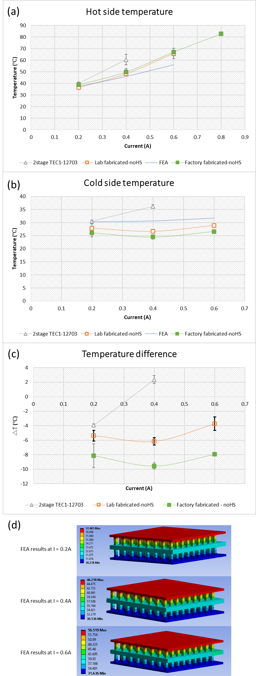
Results for the case where no heat sink is used on the TEC hot side is shown in Fig. 8. For the 2-stage TEC1-12703, at a current of 0.4 A, the hot side increases to 60℃ and the cold side increases beyond 35℃. This exceeds the skin temperature of the human test subject, creating a warming sensation instead of a cooling one. However, due to the combined effects of lower peltier effect, joule heating and back conduction, our lab fabricated TEC was able to maintain a cooling sensation of ∆T=-6.2 ℃ at a current of 0.4A. This is represented by the orange line labelled “Lab fabricated-noHS” in Fig. 8. Beyond 0.4A however, the cold side starts to heat up due to the back conduction as well as increased joule heating.
These results highlight the need to optimize the internal structure of the TEC to meet the needs of the intended use. Specifically for cooling wearable, it is important to reduce the FF. However, the FF cannot be too low, else the thermal-electric phenomenon due to peltier effect will be negated and the temperature difference between the two sides will be insignificant. It is also equally important to increase the temperature difference maintained cross the TEC. Thus, increasing the number of stages and the AR of the legs used in the TEC can help to achieve that. Yet, the number of stages and the AR cannot be increased indefinitely, since larger number of stages require an increase in power consumption which will reduces the coefficient of performance (COP) of the TEC, and the maximum AR is limited by the structural strength of the semiconductor material used for the TEC legs. Therefore, the internal design structure of the TEC is the key to adapting TEC, at its current technology level, for different applications. To perform these optimizations, it is important to make use of numerical methods to perform parametric studies. The numerical model gives insights into the temperature distribution and behavior of the TEC at different current and heatsink configurations at the hot side. The good agreement between our experimental results and the predicted result from this numerical model also confirms the validity of the use of FEA for TEC design.
These TECs that can provide significant cooling sensation, without the need of a heat sink, weigh less than 50g per TEC. A light-weight vest can thus be easily built up using a few of these TECs into a cooling vest. To ascertain this, the team decided to engage a commercial TEC fabrication factory, Zhejiang Changxin Electronic Technology, to fabricate the TEC in a proper factory environment with molding. The resulting performance of the factory fabricated TEC is also presented in Fig. 8 for comparison (green line labelled “Factory fabricated-noHS”). Due to the optimal factory fabrication process, it can be seen that the factory fabricated TEC performed better, bringing the cooling sensation down to about -9.5 ℃, as opposed to the -6.2 ℃ achieved by the lab fabricated TEC. The factory fabricated TEC achieves roughly the same hot side temperature as the lab fabricated TEC, however, it was able to attain better cold side temperature, resulting in the improvement in cooling sensation. This is to be expected, since the material and tooling control in a factory environment is better calibrated than in our lab environment. Despite that, the results comparison in Fig. 8 also validated the efficacy of our lab fabrication protocol for TEC prototyping, since the trends observed are similar when compared with factory fabricated prototype. This further highlights the usefulness of our simple lab fabrication protocol that can help researchers do quick and cheap prototyping for proof of concept designs involving thermoelectric technology.
A vest that consists of 6 of these factory fabricated TECs is then designed and fabricated for further testing. This is discussed in the next section.
4.3. Performance of cooling vest incorporated with TECs without heatsink
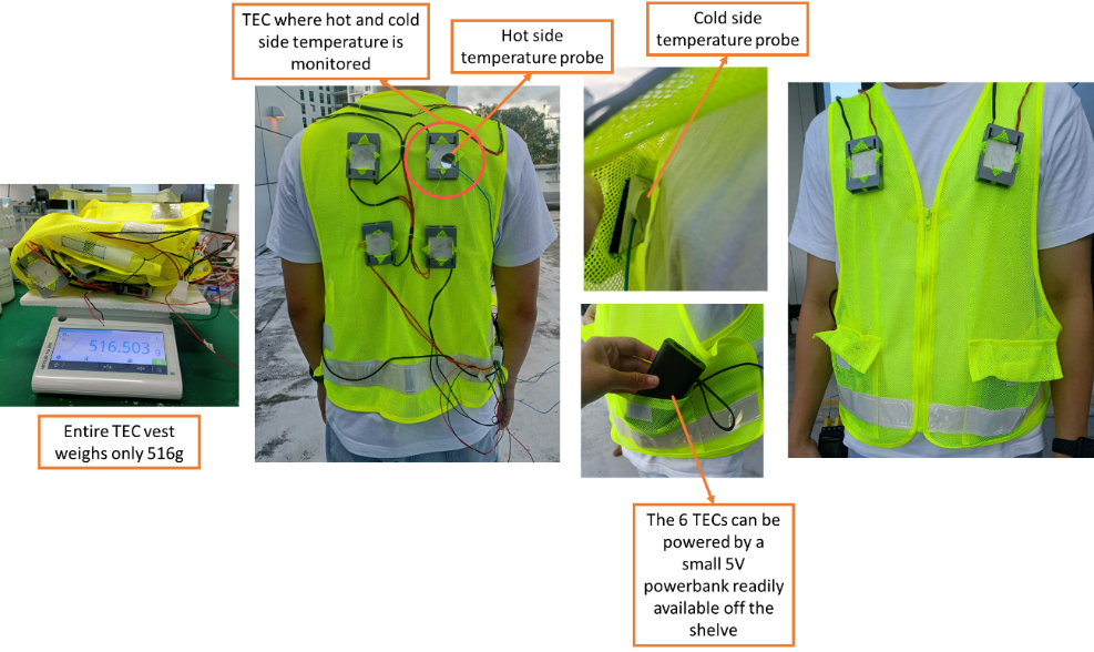
To validate the results found in a laboratory setting, a vest is next designed to incorporate 6 of the designed TECs to test out the TEC’s efficacy in a practical cooling wearable setting. The TECs are placed as shown in Fig. 9, with 4 at the back, and 2 in front at the chest area. Since no heat sink is required, the vest is very light, weighing only 516g using a Mettler Toledo MS1003TS precision balance. Due to the optimized number of legs, the 6 TECs mounted in series can also be powered readily with just a 5V powerbank that is readily available off the shelf. To monitor the thermal performance of the cooling vest, the Center 374 Thermometer is used to monitor the cold and hot side temperature of one of the TEC mounted on the upper back as shown in Fig. 9. On the day of experiment, the outdoor temperature was about 32.1 ℃ with a relative humidity of 67.8 %.
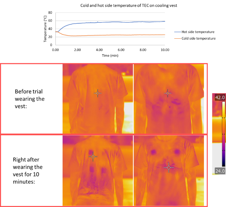
The results of the experimental trial are summarized in Fig. 10. From the thermocouple measurements, a sustained cold side temperature of about 25 ℃ was achieved with a sustained hot side temperature of about 60 ℃. Despite the hotter environmental temperature in this outdoor experiment, the cold side temperature was still able to reach about 25 ℃ as tested in the laboratory. To test if the cold side cooling sensation is felt by the human subject, a thermal image is taken of the human subject’s torso before wearing the vest, and right after the vest is taken off after 10 minutes of experiment time. The FLIR T650sc camera is used for this measurement. A temperature of about 25 to 28 ℃ right beneath the TECs is clearly captured, while the rest of the human torso maintains at about 34 ℃. The vest is also light and easy to wear, and for a relatively large area such as the human torso, the 40 by 40mm TEC although rigid, does not hinder the movement of the human subject.
5. Conclusion
In conclusion, this contribution aims to highlight two important aspects of TEC design and fabrication. Notwithstanding further advancements made to thermal-electric materials to further improve its figure of merit, to achieve good TEC performance for different applications, it is important to optimize its FF, AR as well as the number of stages. The use of a good numerical model, such as that described in this work, can be extremely useful for this structural optimization. Second, experimental validation is equally important to ensure the numerical model is valid. This is because the numerical model requires many parametric assumptions. Experimental results are therefore vital to finetune some of these parameters; for instance, tuning of the convection coefficient h or the thermal resistance assumptions between the TEC and human skin. This work also presents a simple lab-fabrication procedure that can help researchers in quick prototyping of TECs to verify their numerical findings. The resulting TECs fabricated from the fabrication process introduced in this work was able to provide a cooling sensation of -6.2℃ without the need of a heatsink right next to human skin. To validate if the fabricated TEC using our lab-based fabrication procedures accurately represents the performance of factory fabricated TEC of the same design, we engaged external vendors to fabricate the designed TEC. Results show that the trends observed is the same, but due to better equipment and tooling control, factory fabricated TEC achieves lower cold side temperature. With a vest prototype integrated with 6 of our designed factory fabricated TECs, we proved that the prototype can attain a cooling sensation of close to 10 ℃ in both indoor and outdoor settings.
Acknowledgements
This work is supported by the Ministry of Education in Singapore [MOE2020-TIF-0018]. The authors would like to acknowledge Mr Max Goh Han Sheng for his contribution in designing the simple fabrication procedure of the multistage TEC without the need for specialized equipment. The authors would also like to acknowledge Miss Sarah Lim Zhi Yao for her help in fabrication of the TEC.
References
1. J. Ding, W. Zhao, W. Jin, C. an Di, D. Zhu, Advanced Thermoelectric Materials for Flexible Cooling Application. John Wiley and Sons Inc [Preprint] (2021). https://doi.org/10.1002/adfm.202010695. View Article
2. M. Hagenkamp, T. Blanke, B. Döring, Thermoelectric building temperature control: a potential assessment. International Journal of Energy and Environmental Engineering 13, 241-254 (2022). View Article
3. J. Choi, C. Dun, C. Forsythe, M. P. Gordon, J. J. Urban, Lightweight wearable thermoelectric cooler with rationally designed flexible heatsink consisting of phase-change material/graphite/silicone elastomer. J Mater Chem A Mater 9, 15696-15703 (2021). View Article
4. S. Xu, M. Li, Y. Dai, M. Hong, Q. Sun, W. Lyu, T. Liu, Y. Wang, J. Zou, Z. G. Chen, M. Dargusch, Realizing a 10 °C Cooling Effect in a Flexible Thermoelectric Cooler Using a Vortex Generator. Advanced Materials 34 (2022). View Article
5. Y. Zhang, J. Gao, S. Zhu, J. Li, H. Lai, Y. Peng, L. Miao, Wearable Thermoelectric Cooler Based on a Two-Layer Hydrogel/Nickel Foam Heatsink with Two-Axis Flexibility. ACS Appl Mater Interfaces 14, 15317-15323 (2022). View Article
6. Y. Dong, M. Coleman, S. A. Miller, Annual Review of Environment and Resources Greenhouse Gas Emissions from Air Conditioning and Refrigeration Service Expansion in Developing Countries. doi: 10.1146/annurev-environ-012220 (2021). View Article
7. M. Mukherjee, A. Srivastava, A. K. Singh, Recent advances in designing thermoelectric materials. J Mater Chem C Mater 10, 12524-12555 (2022). View Article
8. E. Y. M. Ang, P. S. Ng, C. B. Soh, P. C. Wang, Multi-stage thermoelectric coolers for cooling wearables. Thermal Science and Engineering Progress 36, 101511 (2022). View Article
9. R. A. Kishore, A. Nozariasbmarz, B. Poudel, M. Sanghadasa, S. Priya, Ultra-high performance wearable thermoelectric coolers with less materials. Nat Commun 10, 1-13 (2019). View Article
10. Y. Zhang, J. Gao, S. Zhu, J. Li, H. Lai, Y. Peng, L. Miao, Wearable Thermoelectric Cooler Based on a Two-Layer Hydrogel/Nickel Foam Heatsink with Two-Axis Flexibility. ACS Appl Mater Interfaces 14, 15317-15323 (2022). View Article
11. T. M. Sivarenjini, A. Panbude, S. Sathiyamoorthy, R. Kumar, M. Maaza, J. K, P. Veluswamy, Design and Optimization of Flexible Thermoelectric Coolers for Wearable Applications. ECS Journal of Solid State Science and Technology 10, 081006 (2021). View Article
12. H. Wei, J. Zhang, Y. Han, D. Xu, Soft-covered wearable thermoelectric device for body heat harvesting and on-skin cooling. Appl Energy 326, 119941 (2022). View Article
13. Assessment and validation of a numerical model for phase change materials heatsink on thermoelectric devices. International Communications in Heat and Mass Transfer 155, 107524 (2024). View Article
14. S. Hong, Y. Gu, J. K. Seo, J. Wang, P. Liu, Y. Shirley Meng, S. Xu, R. Chen, Wearable thermoelectrics for personalized thermoregulation. Sci Adv 5 (2019). View Article