Journal of Fluid Flow, Heat and Mass Transfer (JFFHMT)
ISSN: 2368-6111

Volume 11 - Year 2024 - Pages 64-68
DOI: 10.11159/jffhmt.2024.007
Aerodynamic Noise Reduction of Pantograph Head by Small Rods
Masahiro Suzuki1, Nobuyuki Okura 1, Tatsuya Murao 1
1Meijo University, Department of Vehicle and Mechanical Engineering
1-501 Shiogamaguchi, Tempaku-ku, Nagoya, JAPAN 468-8502
msuzuki@meijo-u.ac.jp; ohkura@meijo-u.ac.jp; mtatsuya@meijo-u.ac.jp
Abstract - This paper carries out basic research to advance the development of pantograph head which is more practical, excellent in low noise, and compatible with bidirectional operation. Wind tunnel tests were carried out using a two-dimensional model which simplified the cross-sectional shape of a pantograph head by installing small rods in the front and rear of the head, and the effect of rod installation was evaluated. The results clearly demonstrate that the installation of the rod significantly reduces the noise. Furthermore, the lift force of the pantograph head was found to be stable even when the angle of attack varied.
Keywords: Pantograph, aerodynamic noise, wind tunnel experiment.
© Copyright 2024 Authors - This is an Open Access article published under the Creative Commons Attribution License terms Creative Commons Attribution License terms. Unrestricted use, distribution, and reproduction in any medium are permitted, provided the original work is properly cited.
Date Received: 2023-03-16
Date Revised: 2024-01-11
Date Accepted: 2024-02-13
Date Published: 2024-04-04
1. Introduction
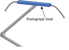
In Japan, since high-speed trains pass through densely populated areas, strict noise regulations are imposed on high-speed trains. The noise of high-speed trains is mainly aerodynamic, especially from the pantograph head (Figure 1), which is located at the top of the pantograph attached to the roof of the train and is in contact with overhead wires [1]. Because aerodynamic sound increases in proportion to the sixth to eighth power of the airflow velocity [2-3], addressing this is critical to improving the speed of high-speed trains.
The pantograph's primary function is to collect current from the overhead wire, and maintaining contact with the wire is essential. However, this consistent contact induces vertical movement in the overhead wire due to its supporting structure. The magnitude of this movement varies depending on the position, leading to vertical oscillations of the pantograph head. These oscillations alter the attack angle of the airflow onto the pantograph head, thereby affecting the lift force acting on it. Large changes in lift force can cause the pantograph head to detach from or damage the overhead wire. Therefore, the pantograph head requires not only low aerodynamic sound performance but also lift stability, in which lift is stable even when the attack angle varies. In addition to these requirements, pantographs must be usable in both directions, as trains operate in both inbound and outbound directions.
To reduce aerodynamic noise, it is desirable to make the cross-sectional shape of the pantograph head streamlined, but streamlined shapes generally have a large change in lift with respect to the angle of attack. On the other hand, a shape in which the lift force does not change much with respect to the angle of attack tends to bluff, and such a shape tends to increase aerodynamic noise. Most pantograph head cross-sections in use today have a shape similar to a rectangle, which emphasizes lift stability.
Various studies have been conducted to enhance aerodynamic sound reduction and lift stability. For instance, Suzuki et al. [4] introduced an optimized pantograph head shape through optimal calculations, validated by wind tunnel experiments. Sato et al. [5] proposed a pantograph head incorporating flow control with a synthetic jet, while Mitumoji et al. [6] suggested a pantograph head with flow field control using a plasma actuator. However, these designs are unidirectional and do not support two-way train operation. Moreover, the upper part of the pantograph head experiences wear from contact with overhead wires, requiring frequent replacement. This makes the implementation of these intricate shapes and mechanisms impractical.
On a different note, Igarashi et al. [7] demonstrated that installing small rods in front of an object could reduce drag. Inspired by this idea, our study investigates the installation of rods in the front and rear of the pantograph head to reduce aerodynamic noise and enhance lift stability potentially. The simplicity of adding rods to the existing pantograph head minimizes costs and allows for compatibility with bidirectional operations.
2. Method
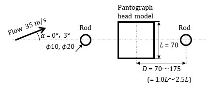
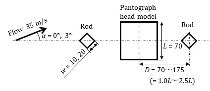
The actual pantograph head is a bar shape with a total length of about 1 meter. For this reason, wind tunnel experiments were conducted here using a two-dimensional model. As mentioned above, most of the actual pantograph heads have a cross-sectional shape similar to a rectangle, so a square cylinder was used as the pantograph head model in this study. The model has a length of 620 mm, and one side (L) of the cross-section measures 70 mm. Small rods were installed in front and behind the pantograph head model (Figure 2). The rods were placed at distances D = 70, 105, 140, and 175 mm from the center of the pantograph head model. These distances are L, 1.5L, 2L, and 2.5L using the length (L) of one side of the pantograph head model. The rods used in the study are categorized into two types: cylindrical rods with diameters of either ϕ10 mm or ϕ20 mm, and square cylinders with a side length (w) of either 10 mm or 20 mm. The square rods were installed at a 45-degree tilt with respect to the rod's central axis because they were highly effective in prior tests. End plates were placed on both sides of the model.
The experiment was conducted using a closed-circuit wind tunnel at Meijo University. The nozzle size of the wind tunnel is 1500⨯1500 mm. The maximum wind speed is 50 m/s and the turbulence level is less than 0.4%.
(a) Circular rods
(b) Square rods
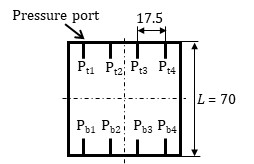
Since this wind tunnel is not an anechoic wind tunnel, accurate noise measurement using a sound level meter is challenging. Therefore, the evaluation of aerodynamic noise was conducted using the following method. The sound pressure level of the Aeolian tone is proportional to the square of the rms of the lift coefficient fluctuation if acoustically compact surface conditions are met and the correlation length is assumed to be constant [8]. Accordingly, the lift fluctuations of the pantograph head model were measured as follows. Four pressure ports were provided on both the upper and lower sides of the central cross-section of the head model (Figure 3), and they were connected to pressure sensors (Amphenol All Sensors, 10 INCH-D1-P4V-MINI) with 50 mm tubes. The length of the brass tube attached to the pressure port was 10 mm, and the length inside the pressure sensor was approximately 10 mm. Consequently, the overall length of the piping system from the pressure port to the diaphragm of the pressure sensor was approximately 70 mm. The resonant frequency (f) of the organ pipe resonance in this piping system is given by f = c / 4Lp ≒ 1.2 kHz (c: speed of sound, Lp: pipe length). As a result, this measurement system enables the measurement of pressure fluctuations below a few hundred Hz. The output of the pressure sensor was recorded on a personal computer via an AD converter (Measurement Computing, USB-1608FS). The sampling frequency was 5 kHz, and the sampling time was set to 6 seconds. The lift coefficient (Cl) was determined from the measured pressure using the following equation,
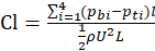
where pbi represents the pressure on the bottom surface, pti represents the pressure on the top surface, i is the pressure port number, l is one-quarter of the side length of the square cross-section, ρ denotes the air density, and U represents the airflow velocity.
The angle of attack of the airflow resulting from the vertical motion of the pantograph head is about ±3 degrees [4]. Since the cross section of the pantograph head model used in this study is square and vertically symmetrical, the angles of attack of the airflow were set to 0 and 3 degrees. The wind speed was set to 35 m/s to account for the range of the pressure sensor, and the Reynolds number based on the side length L of the pantograph head model is 1.6 ⨯ 105.
As noted earlier, due to the wind tunnel not being an anechoic facility, precise noise measurements were unattainable. Nevertheless, for reference, a sound level meter (Rion, NL-52) was placed 1.3 m below the pantograph head (outside the flow) and noise measurements were taken. The duration of the measurements was 60 seconds.
3. Results and discussion
3.1 Effect of Rod Position
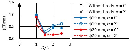
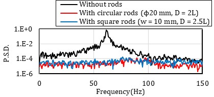
Figure 4 illustrates the relationship between rod position and the magnitude of lift fluctuation. The horizontal axis represents the distance from the center of the pantograph head to the center of the rod, and the vertical axis displays the rms value of the lift coefficient.
(a) Cylindrical rods
(b) Square rods
The value when the rod is not installed is presented at D/L = 0. The rms value of the lift coefficient without the rods in place remains nearly constant at 1.4, regardless of the angle of attack. This finding closely aligns with the value reported by Vickery [9]. Regardless of the size and shape of the rod, lift fluctuations decrease with rod installation. The reduction is particularly significant when rods are installed at D/L = 1.5 or higher. For cylindrical rods, the decrease is more pronounced when the rod is ϕ20 mm. In the case of square rods, there is minimal difference based on the rod's size for D/L ≧1.5. Regardless of the angle of attack, the effect on lift fluctuation is consistently small.
Igarashi et al. [7] positioned a circular rod in front of a square cylinder and observed that the maximum reduction in resistance occurred when the rod position was approximately D/L = 2.0. This finding closely aligns with the results obtained in our experiment. According to Igarashi et al., when the rod is positioned at this location, vortex shedding from the front rod ceases, leading to the formation of an integrated flow field connected between the rod and the square cylinder within the dead water region. This results in the formation of a quasi-steady closed vortex, causing the vortex formation position behind the square cylinder to shift backward, consequently reducing drag. In our experiment, the rods were positioned both forward and backward, while an angle of attack was also introduced. Within this angle of attack, the effect of the forward rod persisted, leading to a reduction in lift fluctuations.
3.2 Power Spectral Density Characteristics of Lift Fluctuation
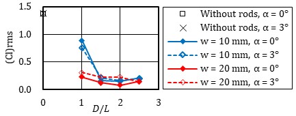
Figure 5 displays the results of the frequency analysis of lift fluctuation. Two cases with substantial reductions in lift variation, observed in the positions mentioned earlier, are compared with the case without rods. The first case involves installing cylindrical rods with ϕ20 mm at D = 2L, and the second case involves installing square rods with w = 10 mm at D = 2.5L, both at an attack angle of 0 degrees. The horizontal axis represents frequency, and the vertical axis shows the power spectral density of the lift coefficient. The black line represents the case without rods, the red line represents the case with cylindrical rods, and the blue line represents the case with square rods. Without rods, the power spectral density spikes around 60 Hz. Calculated using this peak frequency (fp), the Strouhal number (St = fpL/U) is found to be 0.12, closely aligning with previously reported experimental results [9]. Upon installing the rods, there is a significant reduction in the power spectral density in the vicinity of this peak frequency. Igarashi et al. [7] noted a significant rise in the Strouhal number above 0.2 upon installing rods, yet no corresponding spike in the power spectral density around 100 Hz was detected in our experiment.
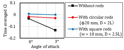
3.3 Variation of Time-Averaged Lift with Angle of Attack
Figure 6 shows the time-averaged lift force for angles of attack of 0 and 3 degrees. Comparisons are made between cylindrical rods with ϕ20 mm installed at D = 2L, square rods with w=10 mm installed at D = 2.5L, and a scenario without any rod. To ensure stable power collection, the lift coefficient must remain within a certain range when the angle of attack changes. Without the rod, the lift decreases as the angle of attack increases from 0 to 3 degrees, whereas with the rod installed, the lift coefficient remains almost unchanged at zero.
3.4 Noise Measurement
The noise measurement results are presented in Figure 7 as reference data. A representative example compares a case with ϕ20 mm cylindrical rods installed at D = 2L to a case without rods, both at an angle of attack of 0 degrees. Without the rod, significant values are observed in the 50 to 75 Hz range, but with the rod installed, values in that range are notably reduced. This aligns with the frequency range discussed in Section 3.2, where lift fluctuations were reduced by rod installation.
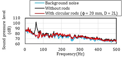
The generation of aerodynamic noise from the rods themselves is a concern. The Strouhal number of the cylinder is reported to be about 0.2 [10], so in this case, the frequency of the aerodynamic sound generated from the ϕ20 mm rod would be 350 Hz. However, no increase in power spectral density was found near that frequency, at least in this result. This observation suggests the intriguing possibility that the vortex emission originating from the forward-installed rod may have ceased, consistent with the findings proposed by Igarashi et al. [7].
4. Concluding remarks
In the endeavor to advance the development of a more practical and low-noise pantograph head capable of bidirectional operation, we conducted fundamental research. Employing a two-dimensional model with a simplified cross-sectional shape of the pantograph head, wind tunnel tests were executed by installing small rods at the front and rear of the head to evaluate the impact of rod installation. The results clearly demonstrate that the installation of the rod significantly reduces the noise. Furthermore, our findings indicated that the lift force of the pantograph head remained stable even in the presence of variations in the angle of attack. These findings provide important knowledge for promoting the practical application of pantographs that satisfy low aerodynamic noise and lift stability at a high level.
5. Acknowledgements
The authors express their gratitude to H. Hayashi, A. Kurata, T. Sasaki, and D. Ishii for their valuable assistance with the experiments.
References
[1] M. Ikeda, Measures against pantograph noise caused by the Shinkansen, Rail International, 1997-5, pp. 35-43, 1997.
[2] M. J. Lighthill, On sound generated aerodynamically, I. General theory, Proc. of The Royal Society of London A, vol. 221, pp. 564-587, 1952. View Article
[3] N. Curl, The influence of solid boundaries upon aerodynamic sound, Proc. of The Royal Society of London A, vol. 231, pp. 505-514, 1955. View Article
[4] M. Suzuki, M. Ikeda, K. Yoshida, Study on numerical optimization of cross-sectional pantograph head shape for high-speed train, J. of Mech. Systems for Transportation and Logistics, vol. 1, pp.100-110, 2008. View Article
[5] Y. Sato, M. Ikeda and T. Mitsumoji, Reduction of aerodynamic noise generated by a pantograph head by using speakerdriven synthetic jet actuators, RTRI Report, vol. 26, pp. 5 -10, 2012. (in Japanese)
[6] M. Mitumoji, Y. Sato, M. Ikeda, T. Sueki and K. Fukagata, A basic study on aerodynamic noise reduction techniques for a pantograph head using plasma actuators, Quarterly Report of RTRI, vol. 55, pp. 184-189, 2014. View Article
[7] T. Igarashi and S. Ito, Drag reduction of a square prism -1st Report, Flow control around a square prism using a small vortex shedder-, Transactions of the JSME, vol. 59, pp.3701-3707, 1993. (in Japanese) View Article
[8] H. Fujita, The characteristics of the Aeolian tone radiated from two-dimensional cylinders, Fluid Dyn. Res. vol. 42, no.1, 2010. View Article
[9] B. J. Vickery, Fluctuating lift and drag on a long cylinder of square cross-section in a smooth and in a turbulent stream, J. Fluid Mech., vol. 25, part 3, pp. 481-494, 1966. View Article
[10] K. Fujita, Y. Ikegami, K. Kobayashi and M. Ohashi, Experimental studies on fluctuating lift force on a single circular cylinder at high Reynolds numbers, J. of Wind Engineering, no. 37, pp. 73-82, 1988. View Article