Journal of Fluid Flow, Heat and Mass Transfer (JFFHMT)
ISSN: 2368-6111

Volume 10 - Year 2023 - Pages 131-139
DOI: 10.11159/jffhmt.2023.017
Comparison of Two Toilet Bowls with the use of CFD
Sefa Manav1, Halil İbrahim Kemaneci1, Boğaç Şimşir1
1Eczacibasi Building Products, Vitra Innovation Center
4 Eylul, Osman Ruscuk Street, Bozuyuk, Bilecik, Turkey, 11300
sefa.manav@eczacibasi.com.tr, ibrahim.kemaneci@eczacibasi.com.tr,
bogac.simsir@eczacibasi.com.tr
Abstract - Toilet bowl design has a major role on cleanliness and hygiene. In the last decade, rimless toilet bowls had important place in ceramic sanitary ware industry due to their rim free structure. This study focuses on two different design of rimless toilet bowls and their cleaning performance. In this comparison, one of them is an existing, the other one is the new developed product. In this study, a commercial software suitable for CFD (Computational Fluid Dynamics) analysis is used. The effect of bowl geometry and water channel structure on cleaning performance are verified by numerical simulations with CFD. It has been demonstrated by CFD analysis that many phenomena like water wall shear stress, water force and turbulent kinetic energy are important parameters for cleaning performance. These parameters are used for better product development.
Keywords: Toilet bowl design, Multiphase flow in toilet, Numerical simulation, Toilet bowl comparison, Rimless Toilet.
© Copyright 2023 Authors - This is an Open Access article published under the Creative Commons Attribution License terms Creative Commons Attribution License terms. Unrestricted use, distribution, and reproduction in any medium are permitted, provided the original work is properly cited.
Date Received: 2023-06-22
Date Revised: 2023-09-01
Date Accepted: 2023-10-20
Date Published: 2023-10-31
1. Introduction
Toilets are cleaned with water from the reservoir. The reservoir can be inside the wall or combined with the toilet. The water coming from the reservoir reaches the ceramic toilet bowl with the help of channels. Toilets are divided in to two categories, in terms washing types. One of them is the rimmed toilet, which is an older technic. Rimmed toilet bowls can also be called ring toilet bowls. In the rimmed toilet, the water reaches the channels located all around above the toilet bowl and washing takes place. Although water passes through the channels, the channels have close sections that are difficult to clean. The other one is rimless toilet bowls, which is the new technic. The toilet bowl does not have a channel around it, instead there is a distributor to guide the water into the bowl. The water distributor is usually located in the longitudinal axis of the toilet bowl close to the inlet. Without having closed section, the rimless toilet bowl is easier to clean and more hygienic. In recent years, manufacturers have developed methods to make the rimless toilet washing performance better. These studies led to the emergence of a new type of washing. In this type of bowl design, the water distributor is placed on the right or left side of the bowl. Therefore, the flow rotates and creates a vortex flow.
After the ceramic product is produced, performance tests are carried out. In addition, toilets in Europe must also comply with current European standards. These are NF EN 33 [1] and NF EN 997 [2] standards, which determine the minimum performance criteria for toilets. A large number of product tests must be made, to achieve adequate performance. Therefore, this method takes a long time and it is costly. Instead, the number of production trials can be reduced with analysis programs. CFD method can be used to understand how water moves inside the bowl surfaces. Before tool production and investment, the performance of the toilet can be predicted using the CFD method, for example Ansys CFX [3] can be used.
Although, there are some studies on the CFD simulation of the bowl washing and water flow in toilets, no comparison study has been carried out in the literature between flushing system on the rimless WC and vortex WC.
Ichiki et al. [4] examined the bowl, which is designed as a rimless toilet bowl, with two types of flow. The first flow is the flush directly from the bowl, the second flow is the flush from the main tank and circulates through the propulsion. Internal flushing was examined in 2 different structures, both the side and the front of the toilet bowl. The first flushing has a weak effect and is used to wash the bowl. The bowl form is also designed in a different form to provide this flushing. The second flushing is from the internally opened channels that allow the actual waste to be disposed of. It provides a kind of water jet and makes direct contact with the wastes, allowing them to be easily disposed of. This allows flushing with less water. The bowl surface where the water flows is designed to get maximum efficiency from the flushing.
Nakamura et al. [5], rimless structure was studied for the combi-closet and a water-jet system was designed. The patent of the system in which the water enters the bowl through a single hole has been obtained. The internal structures that direct the movement of water are examined. Different bowl designs were made and patented.
Pearson [6], talked about rimless toilet bowl and reciprocating flushing. During washing, the path followed by the water was studied. Water enters the bowl at certain angles and through the holes drilled on the right and left. A third hole has been drilled into the system. 6.5% of the water entering the bowl enters from here.
Ichiki et al. [7], rimless toilet bowl was examined. Flushing is done on one side of the bowl. The effects of the side water jet were investigated in 3 different designs. In the first design, water hitting the siphon from the side creates vortex flow. In the second design, the water hits the siphon from the front. In the third design, the water hits the siphon as a closed water jet.
Hayashi et al. [8], In this article, water flow is discussed with and without water jet. In order to vortex the flow in the ducted toilet, the holes in the front are drilled asymmetrically larger than the water inlet. Vortex effect and water jet are used together. Thus, high functional performance is achieved.
Kosugi et al. [9], the water inlet hole and the ring structure change of the ring toilet system were investigated. By changing the hole form, swirl is provided. The channel form is narrowed forward. The bowl form is also designed to assist the vortex movement of the water.
McHale et al. [10], In this study, the American toilet bowl washing system with ring and water jet were examined. Computational fluid dynamics (CFD) analyses were performed. The water channel, through which the water flows before entering the bowl, has been studied in different forms.
A.G.Lopes et al. [11], The movement of water in the toilet bowl was analyzed with Ansys CFX using the 2-phase flow method. The results of the analysis were compared with the results of the real product. The results for the Courant number that occur with different mesh numbers are examined. It has analyzed the new data with the best Courant number and its accuracy has been proven.
2. Geometry
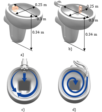
Figure 1 shows Rim-Ex and Quantum Flush WC’s from Eczacıbaşı Vitra products. To reduce variability, both toilet bowl types were analyzed with the same sized bowls.
3D data of products with Rim-Ex WC water distributor structure are shown in Figure 1a and 1c. In this technic, water flows into the bowl from the water distributor placed on it. The water distributor has a three-hole form. Two of these are towards the right and left sides of the bowl. The other hole faces to the bottom of the bowl, where the dead water area is. 70% of the water coming from the reservoir enters the bowl from the right and the left holes of the water distributor and performs cleaning bowl surface. The remaining 30% of the volume enters the bowl directly downstream and applying force on the dead water area. With this force, the feces in the dead water area are moved towards the D5 area, which is the toilet outlet. Therefore, 30% of the volume has no effect on cleaning the bowl surface.
Quantum Flush WC bowl geometry is shown in Figure 1b and 1d. The water coming from the reservoir enters the WC bowl by passing through the triple distributor manifold, which is located inside the bowl and on the side of the bowl. This triple hose is three pieces in a row and has different diameters. By using CFD, hose diameters are optimized to achieve the highest performance. 100% of the water is used to clean the surface of the bowl. The water coming from one side creates a vortex effect inside the bowl.
3. Boundary condition
6 liters of water falls from the reservoir with the effect of gravity and flows into the bowl through the pipes. The static pressure was taken as 1 atm in the open-air boundary condition. The wall is assumed to be frictionless. In this study, the flow is analyzed as turbulent, time dependent and 3D. Three-dimensional continuity and momentum equations solved numerically with Ansys CFX V18.2 [3]. Boundary conditions of Rim-Ex WC and Quantum Flush WC are shown in Figure 2.
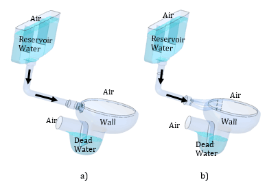
Analysis was carried out considering that the interaction of air and water with each other is homogeneous in multiphase flow conditions. As the initial boundary condition, the water coming from the reservoir at the inlet was taken as F=1 and the air as F=0. Initially, it was assumed that there was air in the bowl and in contact with the open air. Turbulence model was used in turbulent flow conditions. The convergence criterion was taken as 10-4. Thermophysical properties of air and water used in the study are shown in Table 1.
Table 1. Thermophysical properties of air and water at 22°C [14]
|
|
Air |
Water |
|
Density (ρ) [kg m-3] |
1.185 |
997.0 |
|
Viscosity (μ) [kg m-1s-1] |
1.831E-05 |
8.899E-4 |
|
Molar Mass [kg kmol-1] |
28.96 |
18.02 |
In the experimental environment, the movement of water starts with pressing the trigger of the reservoir, enters the bowl and continues until it is discharged from the reservoir. The discharge time of the water was observed as about 10 seconds and the analyzes run time duration is 10 seconds. The time step in the analysis is 0.0001 s. In this study, the Courant Number is 1.25 for 0.0001 s time steps.
4. Meshing
(a)
(b)
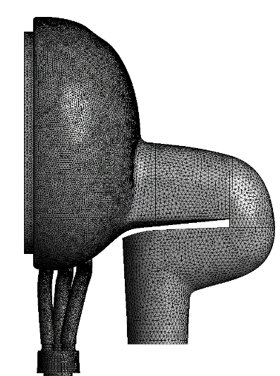
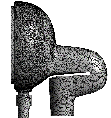
a) Rim-Ex WC, b) Quantum Flush WC
During this study, mesh characteristics were used in the products as in the below Table 2. Sensitive areas were meshed in higher quality to achieve better results. Skewness is a good indicator of mesh quality because necessary to keep discretization errors at low level. Tetrahedral mesh is mainly used. Mesh quality has been increased in areas close to the wall where water is in direct contact. An inflation layer is formed near the walls. Total Inflation layer thickness is 1 mm. Number of inflation layers is 5. The mesh distribution of Rim-Ex WC and Quantum Flush WC is shown in Figure 3.
Table 2. Mesh Characteristics
|
|
Rim-Ex WC |
Quantum Flush WC |
|
Volume Spacing |
3-5 |
3-5 |
|
Skewness |
0.23(0.13) |
0.23(0.14) |
|
Total Nodes |
922000 |
800000 |
5. Theory
In this study, 6 liters of water motion starts from reservoir as free fall and enters the bowl as a turbulent flow. In the Rim-Ex toilet, water enters the bowl through the right, left and middle holes. The water that cleans the bowl surface combines with the so-called dead water at the bottom and throws the dirt out of the discharge pipe. Dead water is defined as still water in the bowl and in the siphon area and varying between about 1000-1300 ml.
In the Quantum Flush toilet analysis, water in the reservoir falls and passes through the manifold and enters the bowl through 3 holes of different diameters and on top of each other. In order to reach the farthest points in the bowl, the bowl surface in front of the triple distributor is shaped to carry the water. The water coming out of the 3-pipe water distributor cleans the bowl surface by rotating about 3 times. With the vortex effect, the bowl washing is also in a better condition compared to the Rim-Ex bowl form. It is assumed that the water has turbulent flow, therefore analyzes run as turbulent flow. Numerical methods are used due to geometry complexity, 2-phase flow and time dependency and Ansys CFX V18.2 [1] was used for analysis. The thermophysical properties of air and water at 22 °C were taken in the analyses.
The standard k—ε model was used in the analyses. The standard k—ε model has two equations, one for k and one for ε. k—ε is used for velocity and length scale. But while when defining large scale eddies, the variable ε is used for small eddies. Because, the rate of transfer of energy must be strictly adhered to against eddies, diffusions and kinetic energy spectra in the ratio of the Reynolds number that extract the large eddy energy in the main flow. In applications to some approaches, such as the mix length model, the specific eddy viscosity can be defined as follows [12].

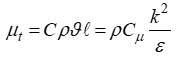
Cμ is the dimensionless constant here. Using the standard model, the k - ε; equations of motion
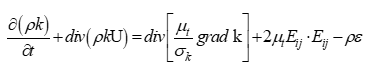
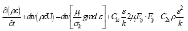
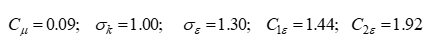
The system of equations includes five constants, Cμ,σk,σε,C1ε and C2ε These constants are used in a wide range of turbulent flow.
The terms of product and distribution are always almost in the same connection in turbulent kinetic energy. The dispersion ratio k is large when ε is large. If k falls, ε also falls to avoid the negative effects of turbulent kinetic energy.
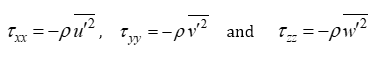
The following equation is used to calculate k - ε and Reynolds stresses.
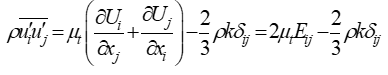
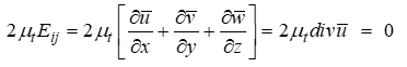
The term ẟij is called the Kronecker delta term. i=j for ẟij1 and i≠j for ẟij=0. For incompressible flow, i=j for
If all normal stresses (at i=1,2,3) , we find the continuity equation, which is also equal to zero [12].
Volume of Fluid (VOF) method is used in the analysis to determine the free surfaces with water-air interface. With the VOF method, it is determined that the cells are empty, completely filled with water or partially filled with water. In this method, a fluid volume (F) is defined over the calculation area. If a cell is completely filled with fluid, it takes the value of 1, if it is completely empty, it takes the value of zero, and if it is partially full, it takes the value of the percentage it occupies in the cell [13]. F is 0 and 1 and also the transition region is shown in Figure 4.
6. Result and Validation
(a)
(b)
a) Rim-Ex WC b) Quantum Flush WC
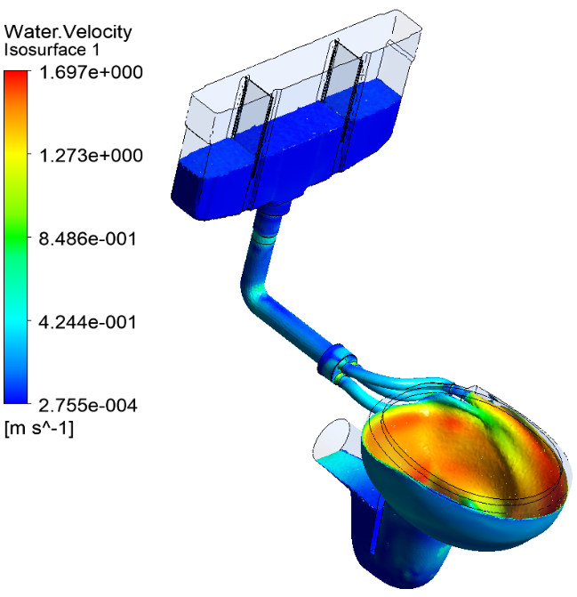
In Figure 5a, velocity gradients are shown as water falls from the reservoir in the Rim-Ex WC at 2 seconds. Unlike Quantum Flush, the water flow moves in 3 different directions, not in one direction. The water coming from the sides is merged in the side part and then this water is poured over the dead water. The water coming from the middle only applies pressure on the dead water. For this reason, the water coming from the middle is not used for bowl cleaning. Therefore , it affects the washing performance negatively.
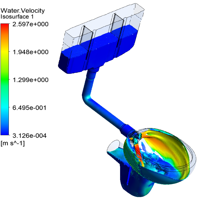
In Figure 5b, velocity gradients are given as water falls from the reservoir in the Quantum Flush WC at 2 seconds. The water in the upper reservoir falls with the effect of gravity and then passes through the manifold and comes to the triple water distributor of different diameters. Then the water passes through the distributor and flows into the bowl. With the water coming from only one direction and the bowl surface geometry being supported, the water coming through the distributor at high flow rate can create a vortex motion and cleans the inside of the bowl surface to every point. Rim-Ex WC and Quantum Flush WC are produced by Vitra, a brand of Eczacıbaşı Building Products. This analysis study was carried out to determine the cleaning performance differences of these two products.
Figure 6. shows the flow rate of WC inlet. Water coming from the same reservoir enters the bowl in Quantum Flush WC with a maximum flow of 1.5 l/s and at the end of 5.4 s the water entry into the bowl becomes 0 l/s. In Rim-Ex WC, on the other hand, water enters the bowl with a maximum flow rate of 1.3 l/s and becomes 0 l/s after 6.5 seconds. Therefore, water enters the bowl 1.1 s faster from the reservoir. Showing that the resistances in Quantum Flush WC 3-pipe structure are less than Rim-Ex WC.
Figure 7. shows the flow rate of WC outlet. The Quantum Flush WC output flow rate is higher than the Rim-Ex WC and also Rim-Ex WC, the water starts to drain while it is still 0.5 s. In Quantum Flush WC, on the other hand, discharge to the drain starts at 1.75 s. This shows that water stays in the bowl longer in Quantum Flush WC and the bowl is cleaned with more water by vortex effect.
Figure 8. displays amount of water in bowl. The amounth water held in the bowl of Rim-Ex WC and Quantum Flush WC. Quantum Flush WC washes the bowl in 10 seconds, 57% better than Rim-Ex WC. Considering the total amount of water in the bowl, there is a maximum of 3.1 liters in Quantum Flush WC, and a maximum of 1.6 liters in Rim-Ex WC. For Quantum Flush WC, it is seen that more water is cleaning the inside of the bowl with the vortex effect.
Figure 9. shows shear stress value affecting the inside of the bowl wall is 2.95 Pa at maximum in Quantum Flush WC, the wall shear stress value affecting the bowl surface of Rim-Ex WC is 1.75 Pa in the same time period. The wall shear value of the water in the bowl for 5 s is quite high in Quantum flush WC compared to the other. This shows that Quantum Flush WC removes more dirt attached to the surface.
Figure 10. displays the force of the water acting on the bowl surface. This Force is important for removing waste from the bowl surface. The force acting on the Quantum Flush bowl is higher than Rim-Ex WC. For the Rim-Ex WC, water force is high in the first 0.25 seconds. Then, the energy of the water coming from the reservoir decrease. In Quantum Flush WC, water force is generally higher. In both products after 5.5 second, water force decrease significantly and reaches zero an 10 seconds.
Figure 11. shows the turbulent kinetic energy of the water entering the bowl at the outlet of the flow distributor. Turbulent kinetic energy shows the irregularities, turbulence and eddies in the flow. The high turbulance reduces the water energy, causing water not reaching farthest points in the bowl. Also, high turbulence kinetic energy cause of noise. In the first 0.25 seconds, the turbulence kinetic energy values of both products are close to each other and high. This is because the water is free falling from the reservoir at the same height. After the first impact, the turbulent kinetic energy level in the Rim-Ex toilet bowl increases even more. The reason is the intensity and scattering of the water coming from the right, left and middle holes. On the other hand in Quantum Flush WC, there is a very smooth spread after the first effect. Water enters through pipes of different diameters in a controlled manner and parallel to the bowl wall. There is no collision like Rim-Ex technic.
7. Conclusion
In this study, two different flushing systems were compared. One, Vitra Rim-Ex toilet, which has been mass-produced since 2013 and has proven itself as industry standard. The other is Vitra Quantum Flush toilet, the newly developed.
Water falls from a certain height and reaches the toilet bowl by passing through the designed channels. For a better cleaning performance, the potential energy of the water should be used in the most efficient way. In Quantum Flush WC, since the water channels inside the toilet are optimized for this purpose, the water reaches the bowl by preserving its energy.
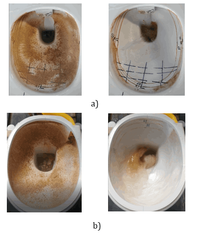
a) Rim-Ex WC b) Quantum Flush WC
Numerical simulations have become quite important in designing new products, developing products and in particular solving problems. In recent years, CFD software has been widely used in new product design and development stages, especially in ceramic sanitary ware. Quantum Flush WC and Rim-Ex WC bowls and flushing types mentioned in this study were also developed with Ansys CFX simulation program. The aim is to analyze the movement, distribution and effect of the water in the bowl while it is still in the design phase. In addition, it has been tried to establish a relationship between the movement of the water entering the bowl and the washing performance.
Bowl geometry design was made, and development time was reduced by using the simulation program. The comparisons mentioned in this study has also been revealed with numerical simulation program.
In Figure 12, images of saw dust test of Rim-Ex WC and Quantum Flush WC are shown. Saw dust test is defined in NF EN997 [2]. At the beginning of the test, the bowl is covered with sawdust, after which it is flushed to see where the water reaches. Figure 12a shows the image of Rim-ex WC at the beginning of the test and at the 2. second. Figure 12b shows the image of Quantum Flush WC at the beginning of the test and at the 2. second. Accordingly, it has been revealed that the simulation made gives very close results to the real flow.
Analyzes were made with the same boundary conditions, close mesh properties and the same numerical model, and data were taken for 10 seconds. Two different washing systems were compared numerically in terms of the amount of water entering the bowl, the amount of water leaving the toilet, the amount of water remaining in the bowl, the water force inside the bowl, the wall shear stress affecting the bowl surface and the turbulent kinetic energy. As a result of these comparisons, the newly developed Quantum Flush WC performs better than the Rim-Ex washing system in all the above-mentioned characteristics. Considering all these findings, it was decided to produce the newly developed Quantum Flush WC toilet.
Acknowledgements
This study was carried out within the Eczacıbaşı Vitra Innovation Center and with the financial support of Eczacıbaşı.
References
[1] Cuvette de WC a alimentation independante et cuvettes de WC a reservoir attenant ( WC pans and WC suites - Connecting dimensions), NF EN 33, October 2011.
[2] Cuvette de WC et cuvettes a reservoir attenant a siphon integre ( WC pans and WC suites with integral trap ), NF EN 997, May 2012.
[3] Ansys 14.5, (2018) Tutorial CFX Multiphase, L1 - L10.
[4] Ichiki, T., Ozeki, T., Yoneda, T., Shibata, S. and Nagashima, S., 2011, Flush Toilet, United States Patent Application Publication, P. No: 2011/0023224 A1.
[5] Nakamura, K., Ozeki, T., Yoneda, T., Ichiki, T., Tomonari, H., Asada. K., Kawakami, K., 2010, Flush Toilet, United States Patent Application Publication, P. No: 7661153B2.
[6] Pearson, J., 2009, RimlessToiletwithflushWater Distribution Apparatus, International Application Published Under The Patent Cooperation Treaty, P. No: 2009/030904
[7] Ichiki, T., Ozeki, T., Yoneda, T., Shibata, S. and Nagashima, S., 2010, Flush Toilet, United States Patent Application Publication, P. No: 7827628 B2.
[8] Hayashi, R., Wijaya, K., Arita, K., Tsukada, R., Shibata, S., Matsushita, H., 1999, High Performance Flush Toilet, United States Patent Application Publication, P. No: 5983413.
[9] Kosugi, T., Sugita, T., Ogawa, K., Tokunaga, H., Ohtani, T., 2003, Toilet and Method for Manufacture of The Same, United States Patent Application Publication, P. No:0115664 A1.
[10] McHale, J., Bucher, C., Grover, D., Zhou, J., 2012, High Performance Toilet with Rim-Jet Control Capable of Enchanced Operation at Reduced Flush Volumes., United States Patent Application Publication, P. No:0198610 A1 .
[11] Lopes A. G. And Costa A.F.V., 2019, Using CFD in the Design Process of a Toilet Bowl, Journal of Fluid Flow, Heat and mass transfer, Vol. 6 View Article
[12] Versteeg, H.K. and Malalasekera, W., 1995. An Introduction to Computational Fluid Dynamics: The Finite Volume Method, Longman Group Ltd., Harlow, England.
[13] Hirt, C. W. and Nichols, B. D., 1981. Volume of Fluid (VOF) Method for the Dynamics of Free Boundaries. J. Comput. Phys., 39, pp. 201-225. View Article
[14] Incropera, P.F., DeWitt D.P, 2001, Isı ve Kütle Geçişinin Temelleri, (Çev. Derbentli, T., Genceli, O., Güngör, A., Hepbaşlı, A., İlken. Z., Özbalta. Ö., Özgüç, F., Parmaksizoğlu, C., Uralcan, Y.) , Literatür Yayıncılık, Y. No: 51, İstanbul