Journal of Fluid Flow, Heat and Mass Transfer (JFFHMT)
ISSN: 2368-6111

Volume 10 - Year 2023 - Pages 97-105
DOI: 10.11159/jffhmt.2023.013
Drag Reduction of a NACA Aerodynamic Airfoil: A Numerical Study
Amine Agriss1, Mohamed Agouzoul, and Abdeslem Ettaouil
Mohammed V University in Rabat, Mohammadia School of Engineers, Avenue Ibn Sina, P.O. Box 765-Agdal,
Rabat, Morocco
Mechanical and Energetic Engineering Research Team: Modelling and Experimentation ERG2(ME)
1amineagriss@research.emi.ac.ma
Abstract - The primary goal of this research is to introduce a novel method for reducing drag of the NACA 0012 airfoil, aiming to enhance its aerodynamic performance. This involves strategically placing a specialized device in areas where flow separation occurs. The primary purpose is to decrease drag of the airfoil, ultimately leading to improved efficiency. To thoroughly explore this approach, extensive two-dimensional numerical simulations have been carried out, employing the computational fluid dynamics (CFD) capabilities of Ansys Fluent 17.0. The analysis is based on conditions of incompressible and laminar airflow, with particular focus on a Reynolds number of Re = 1000 and a 5° angle of attack. The resultant outcomes highlight instances in which the device effectively reduces drag while simultaneously enhancing the lift-to-drag ratio. Looking ahead, future research works include a more comprehensive investigation of this innovative drag reduction device across a wider range of angles of attack, thereby expanding its potential applications.
Keywords: NACA 0012, airfoil, flow separation, Ansys Fluent, laminar, drag, lift-to-drag.
© Copyright 2023 Authors - This is an Open Access article published under the Creative Commons Attribution License terms Creative Commons Attribution License terms. Unrestricted use, distribution, and reproduction in any medium are permitted, provided the original work is properly cited.
Date Received: 2023-08-14
Date Revised: 2023-09-20
Date Accepted: 2023-09-25
Date Published: 2023-10-02
1. Introduction
Aerospace engineering's focus on enhanced aerodynamic efficiency underscores the significance of well-designed airfoils, crucial for optimal performance across applications like aircraft and wind turbines. The NACA 0012 airfoil, an extensively examined profile, continues to captivate attention due to its symmetrical shape and fluid dynamics relevance. With innovative techniques, including computational simulations and advanced materials, researchers aim to uncover principles governing flow interactions and create effective drag reduction strategies.
A variety of drag reduction techniques have been employed on the NACA 0012 airfoil, showcasing the versatility of strategies to enhance aerodynamic efficiency. Among these techniques, using microcylinder to control flow could improve airfoil performances [1]. The addition of an attached Gurney flap has the potential to enhance the aerodynamic characteristics of the NACA 0012 airfoil [2]. The use of a micro-riblet film allows controlling airflow around a NACA 0012 airfoil [3]. The aerodynamic performance of H-Type NACA 0021 Darrieus rotor could be improved using leading-edge stationary/rotating microcylinders [4]. Blowing and suction jets applied on a wind turbine airfoil improve its aerodynamic performances [5]. Implementing vortex generators for flow control on the NACA 4415 airfoil enhances its effectiveness [6]. Active flow control by suction could delay the boundary layer separation for NACA 4412 and improve its performance [7]. Under certain conditions, the implementation of fluid injection winglets have the potential to decrease drag and enhance the efficiency of the NACA 0012 airfoil [8].
Various other simplified models serve as testbeds for evaluating drag reduction techniques. These models encompass flat plates and simplified car geometries, both offering insights into effective drag reduction strategies. For instance, introducing corrugations on the surface of flat plates has demonstrated the potential to minimize drag [9]. Similarly, a drag reduction approach involves introducing controlled airflow into the rear end of the Ahmed body using a conduit [10]. These techniques, along with a multitude of other drag reduction strategies, have been explored and documented extensively in the literature.
This study aims to minimize drag experienced by the NACA 0012 airfoil through innovative techniques [11]. To achieve this goal, a device is strategically positioned at the separation point on the airfoil, enabling efficient separation control and subsequent drag reduction. Ansys Fluent 17.0, a computational fluid dynamics software, has been utilized to conduct extensive numerical simulations. Diverse setups of the control device are examined to identify optimal configurations. Notably, aside from its drag-reducing effects, the most effective configuration also demonstrates an enhanced lift-to-drag ratio, showcasing its potential for improved aerodynamic performance.
2. Test case description
The objective in this work is minimizing drag of the NACA 0012 airfoil without reducing it efficiency. That’s means that the lift-to-drag ratio shouldn’t decrease.
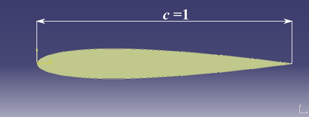
Figure 1 illustrates the NACA 0012 airfoil, with a 1 m chord length (c=1 m), which is employed as the subject of this study. The numerical simulations are conducted under a Reynolds number of Re=1000.
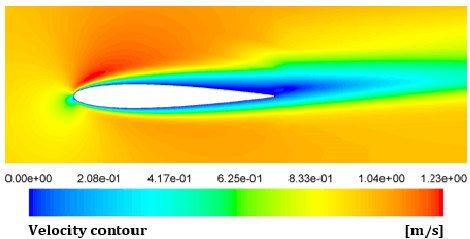
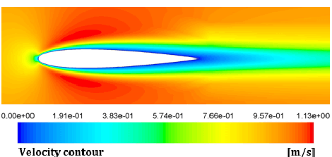
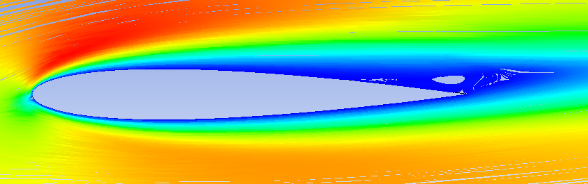
In this study, the focus is on the angle of attack 5°. A numerical simulation considered NACA 0012 without this new device is performed. Figure 2 illustrates the velocity contours in the case of flow over the NACA 0012 airfoil with 5° angle of attack.
The program used in the context of this study (ANSYS FLUENT 17.0) enables the determination of the flow separation point. In this case, this point is situated 0.6 m away from the front edge. This is the point from which the wall shear stress becomes zero.
In Figure 3, it is evident that the wall shear stress becomes zero on the NACA 0012 airfoil starting at a point located at a distance 0.6 m from the leading edge.
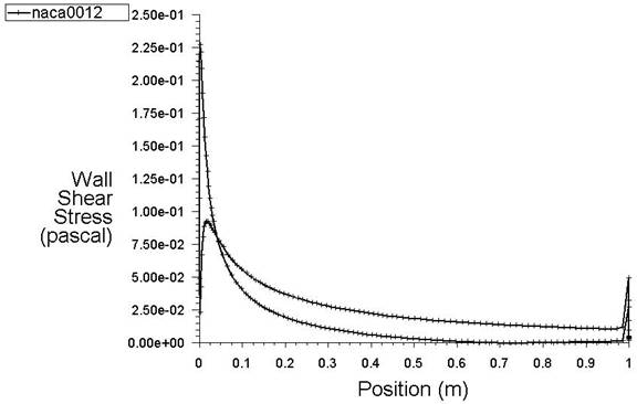
Figure 4 depicts the device attached to the airfoil, specifically at the location where flow separation may occur.
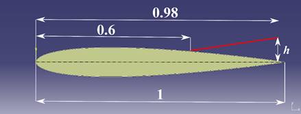
Multiple configurations have been assessed by varying the length 'h', which defines the orientation of the device.
3. Computational modeling
In this research, a steady-state simulation is conducted using incompressible and viscous airflow, with the Reynolds number set at Re=1000. Navier-Stokes equations for steady-state, incompressible, and laminar flow describe the conservation of momentum and the relationship between velocity, pressure, and viscosity. In vector form, they can be expressed as follows:
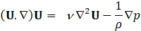
where:
- ρ is the air density.
- U is the velocity vector which has two components u and v.
- ∇ is the del operator (nabla), representing the gradient.
- p is the air pressure.
- ν is the air cinematic viscosity.
The Reynolds number can be expressed as:

where:
- c represents the airfoil chord.
- U is velocity of the incoming airflow.
The aerodynamic coefficients allow evaluating the airfoil efficiency. They are defined by:


where:
- Cd is the drag coefficient and Fd is the drag force.
- Cl is the lift coefficient and Fl is the lift force.
- S is the reference area, which is taken as the wing's area. In situations involving two-dimensional flows, the airfoil's chord is taken as the reference area.
To assess the airfoil's aerodynamic efficiency, we calculate the lift-to-drag ratio, denoted as the L/D ratio, using the following definition:

An airfoil with a greater L/D ratio is more efficient compared to an airfoil with a lower ratio.
4. Numerical processing
This section presents the numerical solution components of our problem, starting with the boundary conditions, followed by the numerical resolution parameters, and ultimately the obtained results.
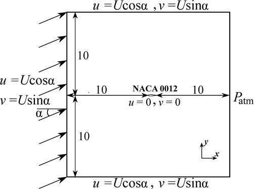
4. 1. Boundary conditions
The boundary conditions are described in Figure 5. The velocity components vary with the angle of attack (u=Ucosα,v=Usinα).
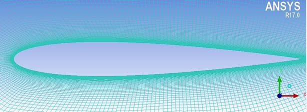
4. 2. Numerical parameters
Figure 6 displays the mesh utilized in this investigation. The mesh is generated using the ICEM 17.0 software tool [12]. Its resolution has been enhanced in zones demanding greater computational accuracy, such as the vicinity near the airfoil. Utilizing a non-uniform structured grid comprising 65 800 elements proved to be sufficient for establishing a grid independent solution.
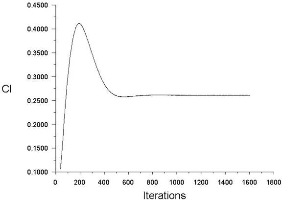
The development of residuals for the continuity and momentum equations is presented in Figure 7. Convergence of solution is reached after 900 iterations. Figure 8 also displays the lift coefficient convergence.
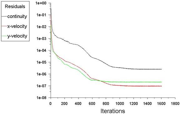
The simulations are carried out under laminar steady-state conditions, utilizing a cell-based least-squares discretization to solve gradients. The pressure and momentum equations are solved using a second-order scheme. The simulations maintain an accuracy level of approximately 10-6.
5. Results and discussions
In this section, numerical results are presented, starting with a comparison with previous findings and concluding with a discussion of the outcomes related to the drag reduction device.
5. 1. Results validation
Figure 9 depicts the velocity contours obtained from the current simulation for flow over a zero angle of attack NACA 0012 airfoil. The shape of the velocity contours obtained is consistent with previous results [13].
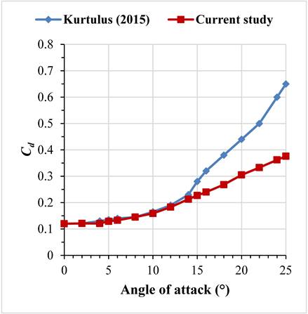
We conduct comparisons between the drag and lift coefficients found in this study and the results documented in prior literature for a range of angles of attack [14]. As shown in Figure 10, for angles of attack ranging from 0° to 14°, both aerodynamic coefficients exhibit a close resemblance to previously documented results. Upon reaching the angle α = 15°, a deviation becomes evident between the aerodynamic coefficients and values reported in earlier studies.
 (a)
(a)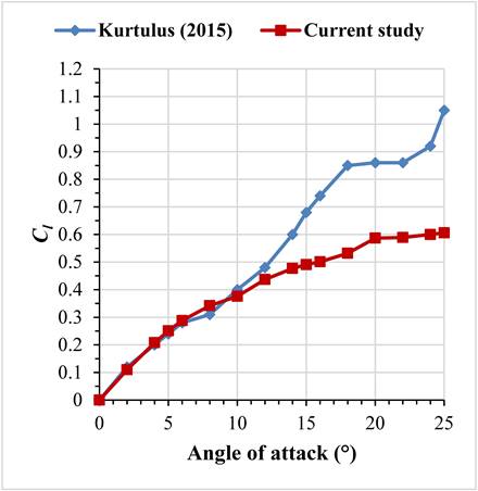 (b)
(b)This divergence can likely be attributed to the flow instability occurring at those specific angles of attack. Similarly, some authors stop their calculations at an angle of attack of 14° [15] or 18° [16]. The largest difference between the current findings and the earlier results [14] is approximately about 42.15% in terms of drag at an angle of attack of 25°. Conversely, for lift, the greatest variance is approximately about 42.86% at an angle of attack of 25°.
5. 2. Results obtained
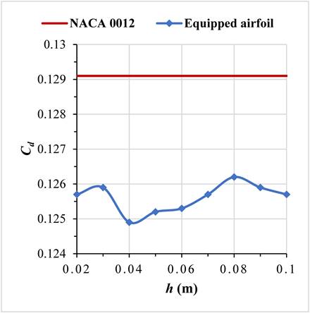
Figure 11 displays the evolution of the aerodynamic coefficients concerning the airfoil with the attached device, relative to the device's height h. Within the range of 0.02 m to 0.1 m for h, there is a reduction in drag coefficients compared to the drag coefficient of the airfoil without the attached device.
The most significant reduction, approximately 3.25%, occurs at h = 0.04 m.
 (a)
(a)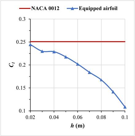 (b)
(b)Simultaneously, the lift coefficient experiences a reduction across all height values. A remarkable reduction is observed starting at h = 0.07 m.
Across all device configurations, a reduction in aerodynamic coefficients is evident, resulting in lower L/D ratios. Notably, only the initial setup with h = 0.02 m shows a reduction in drag and an improvement in the L/D ratio (Cd decreases by 2.63% and Cl decreases by 2.47%).
Tables 1 and 2 represent the drag and lift coefficients Cd and Cl as well as the relative variations ΔCd/Cd and ΔCl/Cl compared to the NACA 0012 airfoil without the device.
Table 1. Drag coefficients achieved for different height h values.
|
h(m) |
Cd | ΔCd/Cd | Cl/Cd |
|
Device-less |
0.1291 |
0 |
1.9427 |
|
0.02 |
0.1257 |
−2.63% |
1.9460 |
|
0.03 |
0.1259 |
−2.48% |
1.8268 |
|
0.04 |
0.1249 |
−3.25% |
1.8335 |
|
0.05 |
0.1252 |
−3.02% |
1.7380 |
|
0.06 |
0.1253 |
−2.94% |
1.8563 |
|
0.07 |
0.1257 |
−2.63% |
1.4646 |
|
0.08 |
0.1262 |
−2.25% |
1.3273 |
|
0.09 |
0.1259 |
−2.48% |
1.1247 |
|
0.1 |
0.1257 |
−2.63% |
0.8648 |
Table 2. Lift coefficients achieved for different height h values.
|
h(m) |
Cl | ΔCl/Cl | Cl/Cd |
|
Device-less |
0.2508 |
0 |
1.9427 |
|
0.02 |
0.2446 |
−2.47% |
1.9460 |
|
0.03 |
0.2300 |
−8.29% |
1.8268 |
|
0.04 |
0.2290 |
−8.69% |
1.8335 |
|
0.05 |
0.2176 |
−13.24% |
1.7380 |
|
0.06 |
0.2021 |
−19.27% |
1.8563 |
|
0.07 |
0.1841 |
−26.59% |
1.4646 |
|
0.08 |
0.1675 |
−33.21% |
1.3273 |
|
0.09 |
0.1416 |
−43.54% |
1.1247 |
|
0.1 |
0.1087 |
−56.66% |
0.8648 |
Figure 12 shows streamlines of the specific setups. It concerns the NACA 0012 without using the device, the configuration allowing the highest L/D ratio (for a device’s height h = 0.02 m) and the configuration giving the lowest L/D ratio (for a device’s height h = 0.1 m).
 (a)
(a)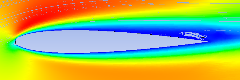 (b)
(b)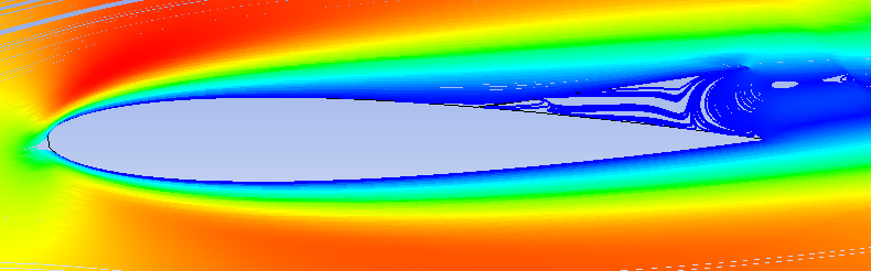 (c)
(c)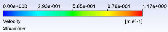
As shown in Figure 12, the use of this device has an impact on the recirculation region behind the airfoil. By increasing the device’s height, the recirculation region begins to increase leading to a decrease in the airfoil efficiency (a maximum lift-to-drag decrease of 55.48% for the device of 0.1 m in height).
The ideal is to place the device in the point where the flow recirculation is likely to occur. However, the length and orientation of the device are important parameters. In this study various device setups have been tested. The configuration with height of h = 0.02 m don’t affect a lot the recirculation region. This explains the fact of reducing drag without really affecting the lift-to-drag ratio (increase of 0.17%).
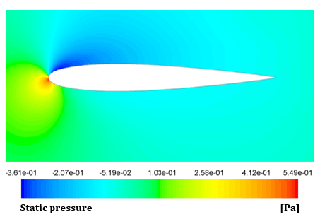
Figure 13 shows the static pressure distributions around the airfoil for these specific configurations.
 (a)
(a)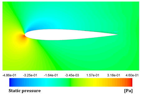 (b)
(b)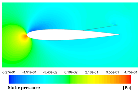 (c)
(c)The static pressure is a vital parameter in aerodynamics. It unveils pressure variations on airfoil surfaces, offering insights into lift and drag.
The airfoil exhibits a more favorable pressure distribution between its top and bottom surfaces when there is no drag reduction device present. When the device is fixed, and when its characteristic height increases, the pressure disparity between the upper and lower surfaces of the airfoil decreases. This observation explains the reduction in lift observed when the device is installed. Additionally, the drag coefficient is also affected by this variation in static pressure. In this context, a decreased pressure difference generally results in reductions in both lift and drag.
One can observe that, in the case of the favorable device configuration (h = 0.02 m), the maximum pressure variation is greater than that of the airfoil without the device. This explains why, for this particular setup, there is no significant reduction in lift. While for the worst case, the maximum pressure variation is reduced. This serves as a clear explanation for the substantial drop in lift within this particular configuration.
To summarize, the idea in this work is to place a device in the point where the separation may occur. This device is characterized by a height parameter, h. Various device setups have been tested and only one configuration is found to reduce drag and enhance the lift-to-drag ratio. A maximal drag reduction of 2.63% and a lift-to-drag increase by 0.17% is achieved for a device of height of h = 0.02 m.
6. Conclusion
This study focuses on the installation of a drag reducing device at the point where potential flow separation occurs on a NACA 0012 airfoil. The main objective is to decrease drag without affecting the airfoil efficiency. Numerical simulations have been conducted using the CFD software Ansys Fluent 17.0.
The strategic placement of the drag reduction device, designed to reduce the flow separation, resulted in reduced drag coefficients across various device setups. This reduction is attributed to the reduction of the recirculation region along the airfoil's surface. However, it's noteworthy that this strategy also causes a reduction in the lift coefficient across all configurations. As a result, it becomes imperative to consider the lift-to-drag ratio, which should surpass that of the airfoil without the device. This criterion is satisfied in a singular design specifically, when the device's height is set to h = 0.02 m.
For the forthcoming research, the focus will shift to exploring the performance of this drag reduction device across different angles of attack. Additionally, there's a suggestion to conduct 3D numerical simulations and experimental studies to validate the current findings.
References
[1] D. Luo, D. Huang, and X. Sun, “Passive flow control of a stalled airfoil using microcylinder,” Journal of Wind Engineering and Industrial Aerodynamics, vol. 170, pp. 256-273, 2017. doi: 10.1016/j.jweia.2017.08.020. View Article
[2] Y. Amini, M. Liravi, and E. Izadpanah, “The effects of Gurney flap on the aerodynamic performance of NACA 0012 airfoil in the rarefied gas flow,” Computers & Fluids, vol. 170, pp. 93–105, Jul. 2018. doi: 10.1016/j.compfluid.2018.05.003. View Article
[3] S.-J. Lee and Y.-G. Jang, “Control of flow around a NACA 0012 airfoil with a micro-riblet film,” Journal of Fluids and Structures, vol. 20, no. 5, pp. 659-672, 2005. doi: 10.1016/j.jfluidstructs.2005.03.003. View Article
[4] W.A. El-Askary, M. Burlando, M.H. Mohamed, and A. Eltayesh, “Improving performance of H-Type NACA 0021 Darrieus rotor using leading-edge stationary/rotating microcylinders: Numerical studies,” Energy Conversion and Management, vol. 292, pp. 117398, 2023. doi: 10.1016/j.enconman.2023.117398. View Article
[5] L. Wang, Md. M. Alam, S. Rehman, and Y. Zhou, “Effects of blowing and suction jets on the aerodynamic performance of wind turbine airfoil,” Renewable Energy, vol. 196, pp. 52-64, 2022. doi: 10.1016/j.renene.2022.06.126. View Article
[6] O. M. Fouatih, M. Medale, O. Imine, and B. Imine, “Design optimization of the aerodynamic passive flow control on NACA 4415 airfoil using vortex generators,” European Journal of Mechanics − B/Fluids, vol. 56, pp. 82–96, Mar. 2016. doi: 10.1016/j.euromechflu.2015.11.006. View Article
[7] R. Azim, M.M. Hasan, and M. Ali, “Numerical Investigation on the Delay of Boundary Layer Separation by Suction for NACA 4412,” Procedia Engineering, vol. 105, pp. 329-334, 2015. doi: 10.1016/j.proeng.2015.05.013. View Article
[8] H. Thimmegowda, Y. Krishnan S, G. S. Gisa and G. R. Vootukuri, “Parametric Study of Fluid Injection Winglet on Aerodynamic Performance of the Wing,” Journal of Fluid Flow, Heat and Mass Transfer (JFFHMT), vol. 9, p. 22-30, 2022. doi: 10.11159/jffhmt.2022.003. View Article
[9] A. Agriss, M. Agouzoul, A. Ettaouil, and A. Mehdari, “Numerical study of new techniques drag reduction: application to aerodynamic devices,” Int. J. Simul. Multidisci. Des. Optim., vol. 12, pp. 16, 2021. doi: 10.1051/smdo/2021015. View Article
[10] A. Agriss, M. Agouzoul, A. Ettaouil, and A. Mehdari, “Numerical Investigation of a Drag Reduction Device Applied to the Ahmed Body,” International Review on Modelling and Simulations (IREMOS), vol. 15, no. 2, Art. no. 2, Apr. 2022, doi: 10.15866/iremos.v15i2.22103. View Article
[11] A. Agriss, M. Agouzoul, and A. Ettaouil, “Numerical Research on a Drag Reduction Technique Used For the NACA 0012 Airfoil,” in Proceedings of the 9th World Congress on Mechanical, Chemical, and Material Engineering (MCM'23), Paper No. HTFF 206, Brunel University, London, United Kingdom –August 06-08, 2023. doi: 10.11159/htff23.206. View Article
[12] Inc. ANSYS. ANSYS Fluent Theory Guide, Release 17.0. Southpointe 2600 ANSYS Drive Canonsburg, PA 15317, January 2016.
[13] R. C. Swanson and S. Langer, “Steady−state laminar flow solutions for NACA 0012 airfoil,” Computers & Fluids, vol. 126, pp. 102–128, Mar. 2016, doi: 10.1016/j.compfluid.2015.11.009. View Article
[14] D. F. Kurtulus, "On the Unsteady Behavior of the Flow around NACA 0012 Airfoil with Steady External Conditions at Re=1000," International Journal of Micro Air Vehicles, vol. 7, no. 3, pp. 301-326, Sep. 2015. doi: 10.1260/1756−8293.7.3.301. View Article
[15] E. C. Douvi, D. P. Margaris, S. D. Lazaropoulos, and S. G. Svanas, "Low Reynolds Number Investigation of the Flow over a NACA 0012 airfoil at Different Rainfall Rates," International Review of Mechanical Engineering (IREME), vol. 7, no. 4, pp. 625-632, 2013. doi: 10.15866/ireme.v7i4.3813. View Article
[16] K. Yousefi, R. Saleh, and P. Zahedi, "Numerical study of blowing and suction slot geometry optimization on NACA 0012 airfoil." J Mech Sci Technol, vol. 28, pp. 1297-1310, 2014. doi: 10.1007/s12206-014-0119-1. View Article