Journal of Fluid Flow, Heat and Mass Transfer (JFFHMT)
ISSN: 2368-6111

Volume 10 - Year 2023 - Pages 86-96
DOI: 10.11159/jffhmt.2023.012
Thermal Response Analysis of a Cross-Flow PCM Heat Exchanger Based on Air and Liquid Flow
Mahdi Momeni1, Saman Jalilian1, Amir Fartaj 1
Department of Mechanical, Automotive, and Materials Engineering, University of Windsor,
401 Sunset Ave, Windsor, Ontario, Canada N9B 3P4
mahdimo@uwindsor.ca; jalilias@uwindsor.ca; fartaj@uwindsor.ca
Abstract - Due to the mismatch between energy supply and demand in thermal systems, this paper introduces a novel phase change material (PCM) heat exchanger based on two working fluids to provide thermal energy storage for the airside. The PCM is integrated into a compact single-slabbed crossflow heat exchanger based on air and liquid flow. A three-dimensional computational fluid dynamics (CFD) simulation is employed to perform a numerical analysis of fluid flow and heat transfer in the model. The dynamic thermal performance of the system is presented for both the PCM charging and discharging processes. The PCM stores excess thermal energy in the charging process, which is then released to the airside during periods of demand when the system's hot working fluid is unavailable. Results have been presented based on fluid temperatures, PCM average solid fraction, PCM phase transition procedure, and heat transfer rates during the charge and discharge processes. It has been observed that, in the discharge process, the stored thermal energy provides the airside with a heating load of 117.9 kJ, which leads to approximately 150 seconds of heating time. Moreover, heat transfer analysis shows that between the air outlet temperature of 28°C and 18°C, latent heat transfer dominates over the sensible heat transfer, causing most of the delay in air outlet temperature drop to occur in this region. Furthermore, it is concluded that using PCM in the heat exchanger can provide extra thermal energy of 100.7 kJ during the discharging process with the share of latent heat of 48% in the PCM heat transfer process. The findings attained in this study will shed light on the development of PCM heat exchangers and guide future research in designing more effective and efficient PCM heat exchangers, leading to enhanced overall system performance.
Keywords: PCM Heat Exchanger, Thermal Energy Storage, Thermal Management; Air and Liquid Flow, Phase Change Material.
© Copyright 2023 Authors - This is an Open Access article published under the Creative Commons Attribution License terms Creative Commons Attribution License terms. Unrestricted use, distribution, and reproduction in any medium are permitted, provided the original work is properly cited.
Date Received: 2023-07-10
Date Revised: 2023-08-28
Date Accepted: 2023-09-10
Date Published: 2023-10-02
1. Introduction
Increasing global economic growth and new sectors have led to a noticeable rise in energy consumption [1]. Among the most important forms of energy, heat is used daily in domestic, commercial, transportation, and industrial settings [2]. Moreover, various investigations related to transport phenomena, including heat transfer, were previously conducted in the fields of turbomachinery [3], renewable energy [4], and porous media [5]. Heat exchangers are considered to be the most crucial component of thermal systems, and their performance influences the entire system's performance [6]. Research has focused on improving heat exchanger thermal characteristics. As a viable solution, incorporating latent heat thermal energy storage (LHTES) of phase change materials (PCMs) in thermal systems has attracted attention in previous research [7]. When PCM is used to store energy within a heat exchanger, LHTES can be stored or released to reduce peak energy demands or provide additional cooling and heating for thermal processes [8]. In order to ensure optimal heat transfer and energy efficiency from the heat exchanger, a transient analysis must be performed on the heat exchanger study [9]. Different types of heat exchangers have been developed over time, but crossflow heat exchangers have been used extensively in various tubular heat exchanger applications, and various experimental and numerical research has been conducted on these exchangers [10]. Thermal characteristics, compactness, and energy efficiency could be improved with an efficient heat exchanger design, such as using minichannels in a compact heat exchanger [11].
In recent years, there has been an increase in interest in the dynamic analysis of heat exchangers for applications that primarily involve heating or cooling to study the control of fluid outlet temperatures. In an experimental study, Fotowat et al. [12] compared the performance of a conventional and meso heat exchanger when the inlet operation conditions were changed in a stepwise manner. The meso heat exchanger achieved a steady state earlier and exhibited significantly higher thermal efficiency than a conventional heat exchanger. A numerical study presented by Ismail et al. [13] focused on forced convection heat transfer simulations in sequential and simultaneous air-to-liquid crossflow heat exchangers. Compared to a sequential heat exchanger module, the second heat exchanger module showed significant improvements in heat transfer rates at a given Reynolds number. In another numerical study provided by the same author [14], the effects of circular channel diameter on the convective heat transfer and pressure drop behavior within thin slabs minichannel heat exchangers were analyzed. According to their findings, pressure drop changes decrease with increasing channel diameter and decreasing Reynolds number. However, for larger diameters and lower Reynolds numbers, there is no significant change in pressure drop. Amagour et al. [15] studied the impact of the rate of fluid flow on the efficiency of thermal energy storage and the process of phase change. They concluded that, compared to the inlet temperature of the fluid, the impact of the mass flow rate of the fluid on thermal energy storage is more significant. Moreover, when increasing the mass flow rate of the fluid, an increase in the rate of phase change and a decrease in the effectiveness was observed. Rahimi et al. [16] experimentally varied the inlet temperature and flow rate of the hot fluid and studied the charging and discharging process of a PCM under each scenario. They showed that the value of the mass flow rate has a significant role in the solidification time. Moreover, they illustrated that when the inlet temperature of the fluid is increased and the flow regime is changed from laminar to turbulent, the melting time decreases. Akgün et al. [17] studied the effect of increasing the temperature and flow rate of the fluids on the charging and discharging process of PCM. They found out that as the inlet temperature is increased, the melting time decreases. Askar et al. [18] experimentally investigated a PCM heat exchanger and showed that using PCM in the heat exchanger can provide 4 minutes of extra air cooling when the coolant flow is not available. Ouzzane and Bady [19] devised a hybrid air cooling system. This system was used for hot climates which integrated a heat exchanger with two-pipe with frozen PCM into an earth-to-air heat exchanger. The results showed that an extension of the air cooling and be achieved by using multiple PCM heat exchangers. Nematpourkeshteli et al. [20], in order to improve the thermal conductivity of the PCM in a triplex-tube heat exchanger, compared various approaches. These approaches were nanoparticles, porous foams, and finned surfaces. They concluded that using nanoparticles and porous foams highly reduces the time needed for melting the PCM, which can be up to 83% improvement. Momeni et al. [21] evaluated the thermal performance of a PCM heat exchanger intended for air cooling. Results showed that increasing the mass flow rate of air reduces the cooling time.
As stated in the previous discussion, conducting a dynamic analysis can provide a valuable understanding of the heat exchanger's thermal performance. As a gap in the literature regarding transient analysis of heat exchangers, using LHTES can improve conventional heat exchangers and provide sustainable thermal management for these systems. By incorporating PCMs, it is possible to establish a sustainable energy system and enhance overall efficiency by effectively managing heat and supplying sufficient thermal energy. In this regard, this study aims to integrate PCM as thermal energy storage in a compact single-slabbed finned air-and-liquid heat exchanger to provide a sustainable energy storage method. The PCM stores excess heat of the hot liquid in the charging process and reliably extends the operating period when the main fluid is temporarily turned off at shutdown time to minimize the need for an external power source or batteries. A comprehensive heat transfer analysis is presented, and the dynamic behavior of the operational fluids and the PCM is studied.
2. Numerical Methodology
To conduct the numerical simulations of the study, three-dimensional (3D) computational fluid dynamics (CFD) is performed based on the finite element method using COMSOL Multiphysics® 6.0 commercial software. The following sections provide a comprehensive description of the numerical modeling procedure.
2.1. Geometry modeling
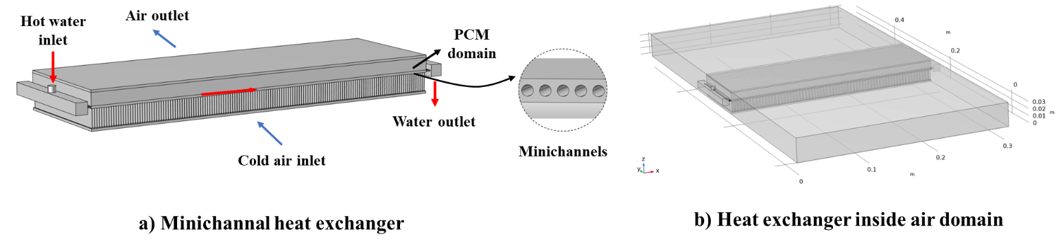
The conventional heat exchanger model is based on a single slab finned air-liquid heat exchanger equipped with minichannel liquid flow operation and PCM. The computer-aided design (CAD) model of the system is shown in Figure 1. The heat exchanger has an aluminum structure and has two rows of fins above and under the main slab. The PCM is placed through the top row of the heat exchanger between the fins. Hot water enters the heat exchanger liquid side and distributes through 68 minichannels inside the slab. The heat exchanger is placed inside the air channel domain seen in Figure 1 (b), which allows the air to pass through the heat exchanger slabs through the bottom fins row and exchange heat with the hot water and the PCM domain. Effective extensive surfaces (fins) are distributed within the PCM domain and between the heat exchanger slabs to enhance the PCM's thermal performance and ensure an efficient heat transfer to the fluids. The design specifications of the PCM heat exchanger are presented in Table 1.
2.2. Operational Setup and Assumptions
The presented heat exchanger based on two operational fluids and PCM storage is designed to provide heating for the airside based on hybrid heat sources of water and the PCM. The hot fluid material is selected water, with an inlet temperature of 70 °C and a mass flow rate of 30 g/s. In the airside, constant inlet temperature and air stream velocity are selected at 13 °C and 2 m/s, respectively. The initial temperature of the model simulation was selected at 20 °C. The entire system was divided into four main domains and materials: aluminum for the heat exchanger domain, water for the channels of the heat exchanger, air for the air channel, and PCM for its designated domain.
The system simulation is presented for the PCM's charging and discharging process. In the charging process, the hot water passes through the heat exchanger slab, melting the solid PCM while heating the air. The water circulation is shut down during the discharging process, enabling the air to extract the latent heat stored in the melted PCM, thereby delaying the air temperature drop and ensuring a warm air outlet. LHTES provides reliable and sustainable heat storage for use during liquid shutdown periods of the heat exchanger.
- The fluids are single-phase and incompressible.
- The thermodynamic properties of aluminum are constant, but air and water are temperature-dependent. For the PCM, thermodynamic properties are constant within a constant phase.
- There is a laminar flow regime in the water and a turbulent flow regime in the air.
- A uniform and homogeneous mass is assumed for the PCM.
- Thermal insulation is considered for the walls of the air domain.
- The system does not transfer heat by diffusion or radiation.
Table 1. Design specifications of the single slabbed PCM heat exchanger based on [22].
|
Specifications |
Value |
|
Number of channels in the slab |
68 |
|
Slab length (mm) |
305 |
|
Slab width (mm) |
100 |
|
Slab height (mm) |
2 |
|
Channel diameter (mm) |
1 |
|
Fin density (fins per inch) |
12 |
|
Fin height – top row (mm) |
10.65 |
|
Fin height – bottom row (mm) |
15.79 |
|
Fin thickness (mm) |
1.85 |
|
Number of fins per row |
144 |
|
Air channel dimensions (mm) |
> |
|
Heat exchanger material |
Aluminium |
2.3. PCM Properties
In thermal management and TES applications, paraffin-based PCMs are extensively used since they have a broad melting temperature range. As a result of its appropriate melting temperature, Docosane is used in this study to accomplish air heating within the heat exchanger's air and liquid sides. Table 2 summarizes the thermophysical properties of the selected PCM.
Table 2: PCM thermophysical properties [23],[24].
|
Material properties |
Value |
|
Commercial name |
Docosane |
|
Melting temperature (°C) |
43.80 |
|
Latent heat of fusion (kJ/kg) |
234 |
|
Average density (kg/m3) |
820 |
|
Material properties |
1700 |
|
Specific heat (solid) (J/kg.°C) |
2200 |
|
Specific heat (liquid) (J/kg.°C) |
0.37 |
|
Thermal conductivity (solid) (W/m.°C) |
0.24 |
|
Thermal conductivity (liquid) (W/m.°C) |
1700 |
2.4. Mesh Grid Generation
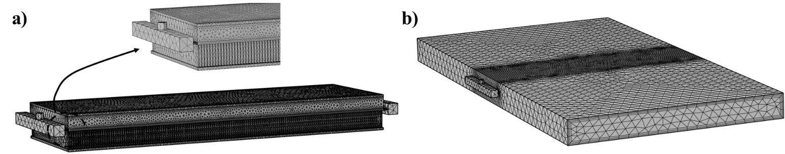
The heat exchanger domains have been divided into several sub-domains: air, liquid channels, and solids (fins and slabs). For the sub-domains of the designed model, free tetrahedral meshes were used to generate mesh grids. To discretize the small geometry regions of the heat exchanger, more refined elements were used. Three boundary layers were considered for the inlet and outlet of the water and air boundaries. To examine the grid dependence of the results, a mesh convergence test is conducted to attain high-quality CFD results. The total grid element number of 1.40×〖10〗^6 is used in the model with an average element quality of 0.31. Figure 2 shows the final meshed geometry for the complete PCM heat exchanger, including the air, PCM, slabs, fins, and water channel domains.
2.5. Governing Equations
Based on the assumptions and model developed in COMSOL Multiphysics, the following main equations are solved in the simulations [21]:
Mass conservation:
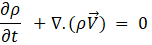
Where ρ is the density, ![]() is the velocity vector, t denotes time, and ∇ is the gradient operator.
is the velocity vector, t denotes time, and ∇ is the gradient operator.
Momentum conservation:
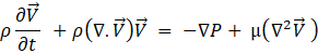

Where P is the pressure, μ is the dynamic viscosity, T is the temperature, β is the thermal expansion coefficient, ![]() donates the gravitational acceleration, and
donates the gravitational acceleration, and ![]() is the Darcy source term which is based on the variation in porosity of the mushy zone. The “ref” subscript denotes the reference state.
is the Darcy source term which is based on the variation in porosity of the mushy zone. The “ref” subscript denotes the reference state.
Energy conservation:

In this equation, H is the total enthalpy and k is the thermal conductivity.
Besides these equations, the software calculates the total latent heat and sensible heat of the PCM. Also, the liquid fraction of the mushy zone is determined to calculate the latent heat share. The thermophysical properties of the PCM at any state are calculated based on the properties provided to the software and the liquid fraction of the PCM. After defining the thermophysical properties of the PCM during phase change, it is possible to solve the energy equation using the apparent heat capacity method.
2.6. Computational Setup and Boundary Conditions
For modeling the physics of the study, laminar flow is used for the water domain, and turbulent flow based on the k-ε model is used for the air domain. Heat transfer in solid and liquid physics is performed on the model to attain the complete thermal behavior of the operating fluids and the PCM. The heat transfer and flow physics are coupled in a Multiphysics simulation. The convective and diffusive terms were approximated using Symmetric Interior Penalty Galerkin (SIPG), and the time derivative was approximated using Backward Differentiation (BDF).
The following boundary conditions were applied for the model simulation:
- Heat transfer liquid and air inlet: average mass flow rate inlet, upstream constant temperature flow inlet
- Heat transfer liquid and air outlet: constant pressure condition
- Air tunnel outer walls: thermal insulation
- Heat exchanger body and heat transfer liquid interior walls: no-slip wall, thermal coupling
3. Results and Discussion
This section presents the numerical results of air heating integrated with TES using latent heat in a PCM heat exchanger. An analysis of the effects of the PCM inside the model is conducted using the operational conditions. The results provide an insight into the response of the charging and discharging processes and the effect of the PCM LTES on extending the heating period to the airside. Several parameters, including the fluid outlet temperatures, the PCM average temperature, and the fluid heat transfer rate, are discussed in this section. Moreover, a comprehensive analysis has been conducted on the sensible, latent, and total heat transfer to the air during the discharging process. Furthermore, in a separate section, the impact of phase change PCM on the heating time provided by the heat exchanger has been demonstrated by comparing the current simulation results with a scenario where the heat exchanger operates without using the PCM.
3.1. Model Accuracy Validation
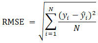
Following the meticulous application of CFD modeling and the utilization of a refined high-quality mesh generation technique, a comprehensive comparative analysis is conducted between the model's outcomes and experimental data acquired under identical operational conditions. This systematic approach ensures a rigorous and accurate validation of the model's precision and reliability. The average dynamic relative errors and the Root Mean Square Error (RMSE) between the dynamic outcomes of experimental and numerical results were compared to determine model accuracy. The RSME is calculated based on the following equation where yi represents the experimental values, ![]() indicates the numerical values, and N is the number of data points:
indicates the numerical values, and N is the number of data points:
The numerical models formulated by Momeni et al. [21,24] were validated through a comparative assessment against experimental and numerical findings conducted by Fotowat et al. [22], Askar et al. [18], and Dehghandokht et al. [25]. In this context, the average relative errors observed during the dynamic operation of the air-heating and air-cooling processes were determined as 3.2% and 3.3%, respectively. Furthermore, for the air-cooling process, the RSME between the transient outcomes was computed at 0.94°C, underscoring the accuracy of the obtained results. The sole modification introduced to the foundational model within the preceding numerical investigation entails the reduction of slab count from five to one, a strategic adjustment aimed at curtailing computational overheads. Consequently, it can be inferred that the outcomes derived from the current system maintain their validity, as corroborated by the computational analyses conducted by Momeni et al. [21,24].
3.2. Dynamic Simulation Results
The CFD model simulated the charging and discharging processes for the operational conditions mentioned. The simulation covered 200 seconds for both processes, with the charging process from t=0-200 s and the discharging process from t=200-400 s. This time interval was found adequate to achieve a steady-state situation for both processes.
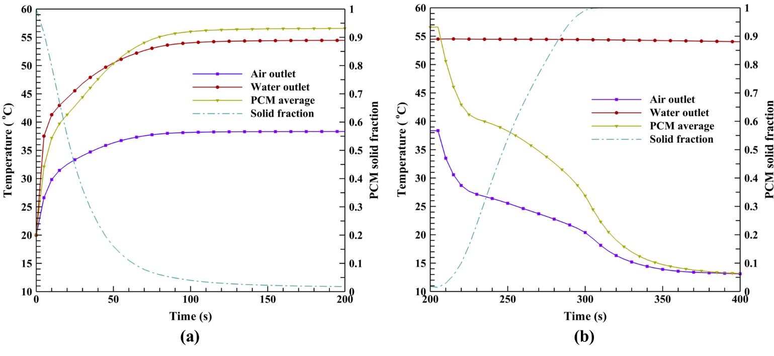
Figure 3 shows the transient plots of air and water outlet temperatures, PCM average temperature, and solid fraction during the charging and discharging processes. During the first 10 seconds of the charging process, it can be seen that the PCM temperature sharply increases. This is because the PCM temperature is lower than its melting temperature, and therefore, it mainly receives the thermal energy of the hot water as the form of sensible heat transfer, causing its temperature to sharply increase. After this period, the PCM temperature reaches its melting range, and consequently, the slope of the PCM temperature curve suddenly decreases, indicating that the PCM has started to receive thermal energy mainly in the form of latent heat transfer. Followed by this phenomenon, the PCM continues to melt and reaches a steady state at 56°C. Moreover, the hot water heats the air while melting the PCM. However, since the slab carrying the hot water is in direct contact with the PCM, the water outlet temperature is highly affected by the PCM domain. Therefore, it can be seen that the trend of the water outlet temperature curve is analogous to the PCM temperature curve (It is steep at first and its slope suddenly decreases after 10 seconds.). Finally, the water outlet temperature reached approximately 54°C at the steady state. On the other hand, the air receives most of its thermal energy from the slab and is less under the influence of the PCM domain. Therefore, its temperature variation gradually decreases and its temperature achieves a steady state at 38°C. Furthermore, the solid fraction of PCM started from the fully solidified state at t=0 s and attained the solid fraction of 0.02 at the end of the charging process. It can be observed that the system temperatures reached a steady state at around 120 seconds.
The discharging process began by shutting down the water inlet at t=200 s, which allowed the thermal energy stored in the PCM to be extracted. At the initial period of the discharging process, it can be seen that the air outlet and PCM average temperatures drop with a sharp slope. The reason for this phenomenon is that the PCM temperature is above its melting temperature range. Therefore, the air receives the thermal energy of PCM mainly in the form of sensible heat transfer. The nature of the sensible mode of heat transfer is to cause substantial temperature variations. Therefore significant temperature drop can be observed for air and PCM during this period. After approximately 20 seconds, the PCM temperature gets close to its melting temperature, and, as a result, the PCM mainly transfers its thermal energy to the air domain via the latent heat transfer mode. This is the reason behind the sudden decrease in the slope of the air and PCM temperature curves after 20 seconds. However, after around 100 seconds, the PCM is fully solidified. Therefore, the heat transfer between the PCM and air domain is again in the form of sensible heat transfer, causing the air outlet and PCM temperature to sharply drop until the system reaches a steady state of 13°C at the end of the discharge process. It can be observed that the LHTES provided additional air heating for around 150 seconds.
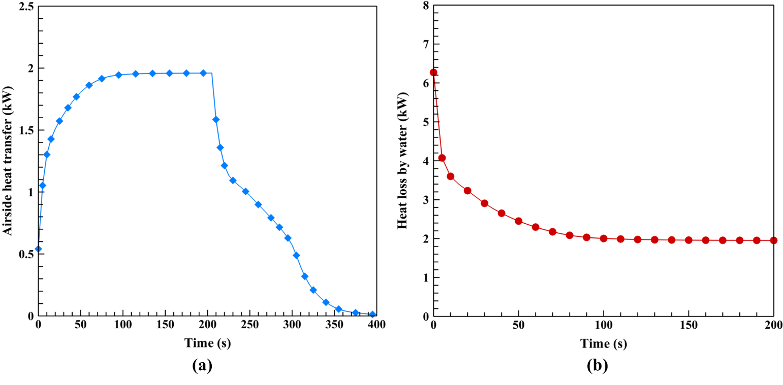
An illustration of the transient behavior of the airside heat transfer rate during the charging and discharging process along with the heat transfer rate of water during the charging process is provided in Figure 4. It is observed that the water side heat transfer drops in the charging process, starting from 6.3 kW and reaching 1.9 kW at the final stage. This is because the water is cooled down during the charging process, heating the air and melting the PCM to store latent heat. The integration through the heat transfer rate plot during the charging process indicates the amount of heat transferred from the hot water to the cold air and PCM during the charging process. This amount is calculated as 467.7 kJ. Observing the airside heat rate plot for the charging process, it is evident that the airside heat transfer starts at a low amount and increases to around 1.9 kW at the end of the process. This is because the air is receiving thermal energy during the charging process, and, therefore, the air outlet temperature is increasing. The total heat the airside received from the hot fluid in the charging process is 364.9 kJ. By subtracting this amount from the total charging heat, 102.8 kJ of energy is attained. Considering no heat losses, this amount is the heat stored in the PCM during the charging process. This energy is later provided to heat the airside in the discharge process. Looking at the airside heat transfer during the discharge process, it is seen that the trend drops while the cold air fully re-solidifies the PCM. The reason for this observation is the gradual depletion of the PCM’s thermal energy, causing the heat transfer rate to the air side to decrease. The amount of energy the charged PCM and the heat exchanger body provide to the air in the discharge process is calculated as 117.9 kJ. This quantity represents the heat that can be delivered to the airside during the discharge process when the hot fluid is shut down, indicating the impact of the PCM's LHTES.
3.3. Sensible and Latent Heat Transfer Plots
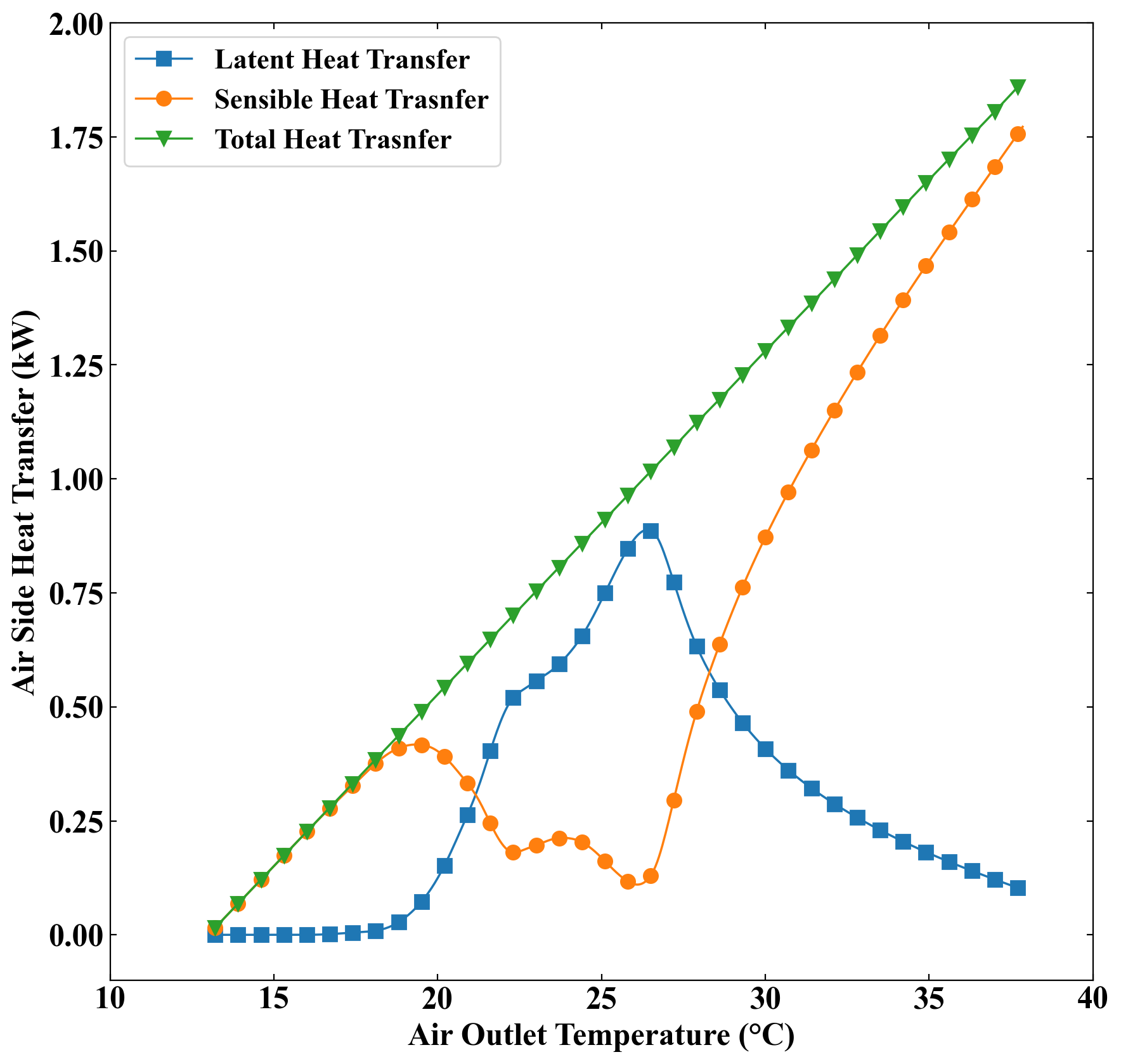
Figure 5 illustrates the relation between the sensible and latent heat transfer as well as the total heat transfer and the air outlet temperature throughout the discharging process. From this figure, it can be seen that, at the beginning of the discharge period, where the air outlet temperature is high, the sensible heat transfer is significantly higher than the latent heat transfer. The reason behind this finding is that at the beginning of the discharging process, the solid fraction of PCM is very low (2%), and also most parts of the PCM are above the melting temperature. Therefore, the phase change in PCM is negligible compared to the temperature drop due to the sensible heat transfer, which causes the sensible heat transfer rate in the PCM to overcome the rate of latent heat transfer. However, as time passes and the air outlet temperature decreases, the sensible heat transfer starts to decrease. This is because a higher percentage of the PCM volume gradually reaches the melting temperature and, therefore, the latent heat transfer becomes more significant. The latent heat transfer surpasses the sensible heat transfer at 28°C. This trend continues and reaches a point (i.e. 26°C) where the latent heat transfer rate becomes maximum. After this point, the temperature of a large portion of the PCM volume falls below the melting temperature which causes the sensible heat transfer to start to rise again and become comparable to the latent heat transfer. However, from Figure 5, it can be seen that when the air outlet temperature falls below 26°C, the latent heat transfer rate does not experience a sharp drop. This is due to the reason that the PCM solid fraction is still considerable and, therefore, the latent heat transfer due to the phase change is strong enough to play a significant role in the heat transfer process to the air. As time passes, the air outlet temperature reaches 22°C and the solid fraction of PCM becomes equal to 0.9. After this point, the phase change process gradually loses its ability to overcome the sensible heat transfer, and as a result, the latent heat transfer decreases at a sharp rate, causing the sensible heat transfer to rapidly increase. This continues until the whole volume of PCM is solidified and the latent heat transfer rate becomes equal to zero at 18°C (t = 300 s). After this time, the heat transfer to the air side is only in the form of sensible heat transfer until the system achieves a steady state at 13°C. The total heat transfer is equal to the sum of latent and sensible heat transfer and has a linear relation with the air outlet temperature.
3.4. PCM Effectiveness
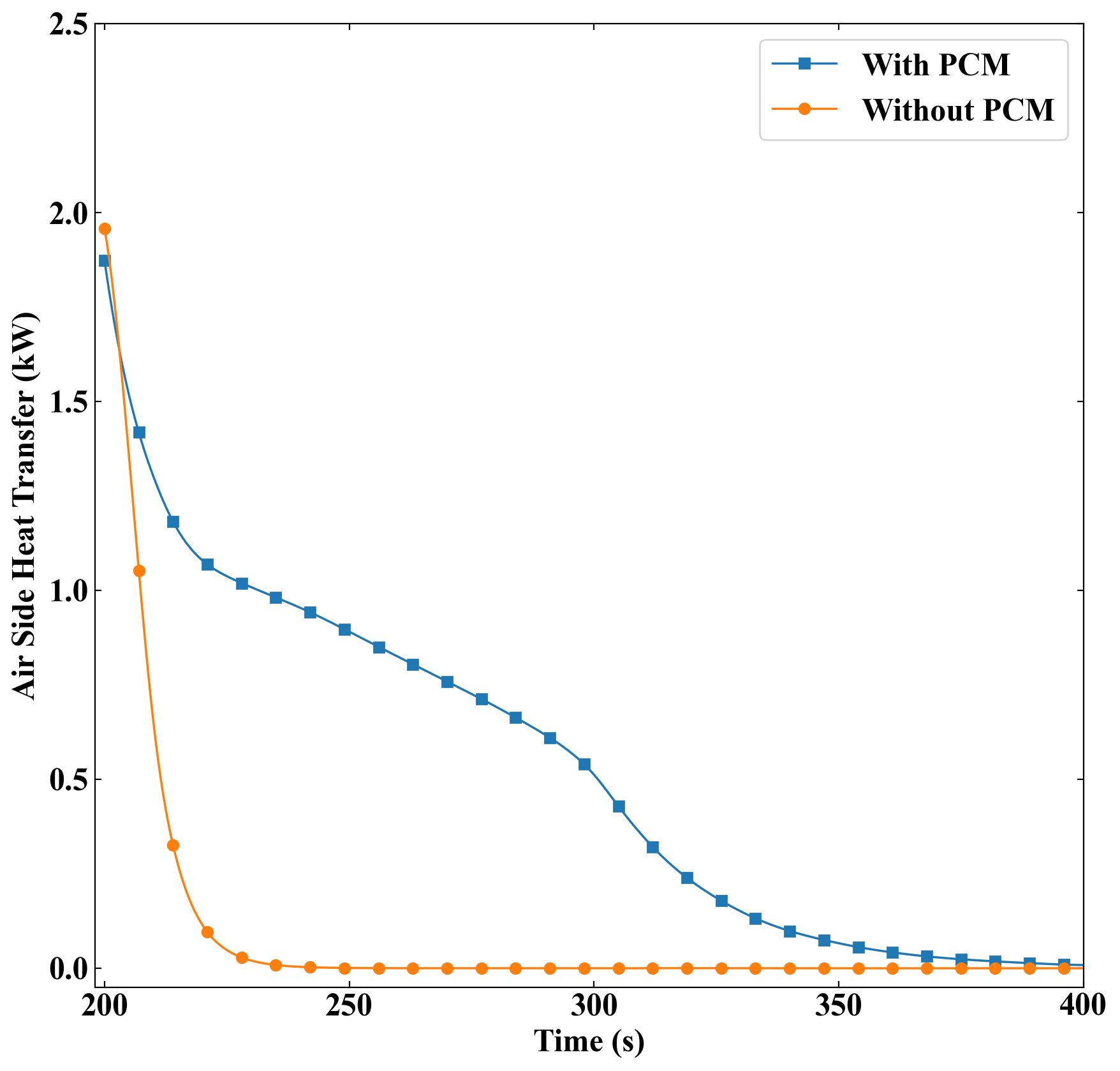
In this section, the influence of employing PCM as a thermal energy storage method in the heat exchanger is explored. To this end, Figure 6 compares the total heat transfer rate in the current system and in a system with similar geometry but without the PCM domain during the discharging process. From this plot, it can be observed that removing the PCM from the heat exchanger causes the air outlet temperature to sharply drop after the hot water is shut down, which is due to the unavailability of thermal energy storage. On the other hand, it can be seen that the PCM provides considerable extra air heating when the discharging process begins. The area under the curves indicates the total thermal energy transferred to the air side during the discharging process. The total thermal energy given to the air for the no-PCM case is calculated as 17.2 kJ. On the other hand, the thermal energy received by air was previously reported as 117.9 kJ. Therefore, implementing PCM in the heat exchanger results in an extra thermal energy of 100.7 kJ. This value is the area between the two mentioned curves. Moreover, by having the mass, latent heat, and the solid fraction of PCM, the total energy stored in the PCM during the charging process is calculated as 57 kJ. Therefore, it can be claimed that the PCM has been 48 % effective. The effectiveness of PCM is the ratio of total thermal energy stored in the PCM during the charging process to the total energy given to the air domain during the discharging process.
3.5. PCM Phase Transition Procedure
To represent the melting and solidification procedure of the PCM during the charging and discharging processes, the 2D phase fraction CFD results of the PCM during different simulation times are illustrated in Figure 5. Graphical solid fraction contours are provided for a cut plain in the middle section inside the PCM domain. It is observed from the charging process contours that the PCM melting phenomenon is initially occurring faster around the inlet of the water, which is on the left and under the PCM domain. The number of 144 thin fins distributed inside the PCM domain highly affects the melting and solidification procedure. Heat is distributed from the hot water by convective heat transfer through fins inside the PCM domain. The PCM plane is gradually melting in the charging process, reaching an almost fully melted position after 60 seconds of operation. The PCM domain's upper side is melting slower since the lower side is in direct contact with the hot slab.
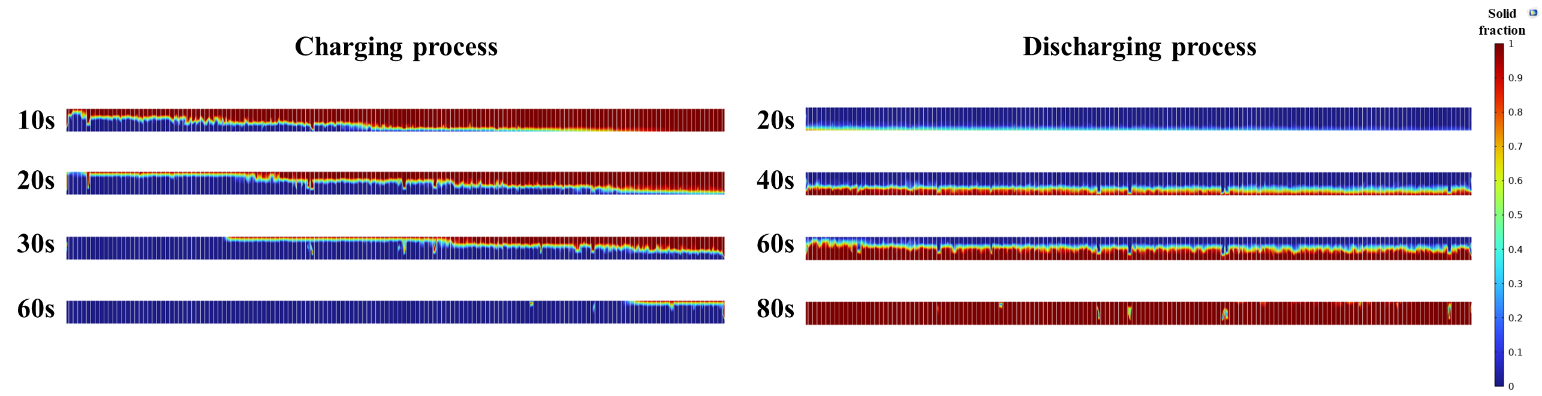
In the discharging process, it can be observed that while air is flowing underneath the PCM block, solidification occurs gradually from the lower to the higher regions of the domain. During convective heat transfer, the thermal energy stored in the PCM domain is transferred to the air, flowing beneath the domain, through the fins. The process of PCM solidification with airflow takes a higher time in contrast to the PCM melting with the liquid flow during the charging process. After 80 seconds of discharge time, the PCM plane has reached an almost entirely solidified state.
4. Conclusion
In this paper, a single slabbed crossflow heat exchanger based on air and liquid flow is equipped with PCM with the purpose of thermal energy storage to provide additional airside heating during liquid shutdown periods. The following conclusions are drawn from the results attained:
- In the charging process, the hot water flow fully melts the PCM providing energy storage of 102.7 kJ for the heat exchanger. This thermal energy stored is released to the airside during the discharge process to maintain air heating.
- Regarding the discharge process, the PCM heat exchanger provides 117.9 kJ of additional heat to the airside resulting in around 150 seconds of extra air heating.
- During the discharging process, the latent heat overcomes the sensible heat transfer when the air outlet temperature is between 18°C and 28°C. The dominance of the latent heat transfer between these two temperatures causes most of the air outlet temperature drop delay to occur between these two points.
- Using PCM in the heat exchanger provides extra thermal energy of 100.7 kJ compared to the no-PCM case during the discharging process. Accordingly, the effectiveness of the PCM is found to be 48%.
- The thin fins distributed inside the PCM domain highly improve the thermal performance and heat transfer process during the melting and solidification.
- The PCM melting process with the hot water flow occurs faster than the PCM solidification time using the cold airflow. The PCM melting and solidification times are attained at around 60 and 80 seconds, respectively.
Acknowledgments
This work was supported by the Natural Sciences and Engineering Research Council of Canada (NSERC) offered at the University of Windsor.
References
[1] M. Momeni, M. Soltani, M. Hosseinpour, J. Nathwani. A comprehensive analysis of a power-to-gas energy storage unit utilizing captured carbon dioxide as a raw material in a large-scale power plant. Energy Conversion and Management. 227 (2021) 113613. View Article
[2] [2] M. Momeni, S. Jani, A. Sohani, S. Jani, E. Rahpeyma. A high-resolution daily experimental performance evaluation of a large-scale industrial vapor-compression refrigeration system based on real-time IoT data monitoring technology. Sustainable Energy Technologies and Assessments. 47 (2021) 101427. View Article
[3] A. Khayyaminejad, N. P. Khabazi, F. Gholami-Malek Abad, and S. Taheripour. Numerical investigation on the effect of the geometric parameters of the impeller on Vortex Pump Performance. Iranian Journal of Science and Technology, Transactions of Mechanical Engineering, pp. 1-21, 2023. View Article
[4] V. Kalantar and A. Khayyaminejad. Numerical simulation of a combination of a new solar ventilator and geothermal heat exchanger for natural ventilation and space cooling. International Journal of Energy and Environmental Engineering, vol. 13, no. 2, pp. 785-804, 2022. View Article
[5] M. Moghaddam, A. Abbassi, J. Ghazanfarian, S. Jalilian. Investigation of microstructure effects on performance of hierarchically structured porous catalyst using a novel pore network model. Chemical Engineering Journal, Volume 388 (2020) 124261. View Article
[6] H. Li, N. Wang, B. Zhao, H. Feng, K. Han, S. He, et al. Simulation study on the effect of fins on the heat transfer performance of horizontal dual-inner-tube latent thermal energy storage heat exchangers. Journal of Energy Storage. 49 (2022) 104125. View Article
[7] L. Kalapala, J.K. Devanuri. Influence of operational and design parameters on the performance of a PCM based heat exchanger for thermal energy storage - A review. Journal of Energy Storage. 20 (2018) 497-519. View Article
[8] S. Rana, M. Zunaid, R. Kumar. CFD analysis for heat transfer comparison in circular, rectangular and elliptical tube heat exchangers filled with PCM. Materials Today: Proceedings. 56 (2022) 637-44. View Article
[9] S. Askar, S. Fotowat, A. Fartaj. Transient experimental investigation of airside heat transfer in a crossflow heat exchanger. Applied Thermal Engineering. 199 (2021) 117516. View Article
[10] C.K. Mangrulkar, A.S. Dhoble, S. Chamoli, A. Gupta, V.B. Gawande. Recent advancement in heat transfer and fluid flow characteristics in cross flow heat exchangers. Renewable and Sustainable Energy Reviews. 113 (2019) 109220. View Article
[11] F.A. Siddiqui, E.S. Dasgupta, A. Fartaj. Experimental investigation of air side heat transfer and fluid flow performances of multi-port serpentine cross-flow mesochannel heat exchanger. International Journal of Heat and Fluid Flow. 33 (2012) 207-19. View Article
[12] S. Fotowat, S. Askar, A. Fartaj. Experimental transient response of a minichannel heat exchanger with step flow variation. Experimental Thermal and Fluid Science. 89 (2017) 128-39. View Article
[13] M.S. Ismail, M. G. Khan, A. Fartaj. Investigation of Sequential and Simultaneous Crossflow Heat Exchangers for Automotive Application. 2020. View Article
[14] M.S. Ismail, S. Fotowat, A. Fartaj. Effect of Channel Size on Heat Transfer and Pressure Drop in Thin Slabs Minichannel Heat Exchanger. 2014. View Article
[15] M.E.H. Amagour, A. Rachek, M. Bennajah, M. Ebn Touhami, Experimental investigation and comparative performance analysis of a compact finned-tube heat exchanger uniformly filled with a phase change material for thermal energy storage, Energy Conversion and Management (2018) 137-151. View Article
[16] M. Rahimi, A.A. Ranjbar, D.D. Ganji, K. Sedighi, M.J. Hosseini, Experimental investigation of phase change inside a finned-tube heat exchanger, Journal of Engineering. (2014), 641954 View Article
[17] M. Akgün, O. Aydın, K. Kaygusuz, Experimental study on melting/solidification characteristics of a paraffin as PCM, Energy Conversion Management. 48 (2007) 669-678. View Article
[18] S. Askar, S. Fotowat, M. Momeni, A. Fartaj, Transient experimental study of a latent heat thermal energy storage in a heat exchanger for effective thermal management, Journal of Energy Storage 55 (2022), 105680. View Article
[19] M. Ouzzane, M. Bady, Investigation of an innovative Canadian well system combined with a frozen water/PCM heat exchanger for air-cooling in hot climate, Applied Thermal Engineering 213 (2022), 118737. View Article
[20] A. NematpourKeshteli, M. Iasiello, G. Langella, N. Bianco, Enhancing PCMs thermal conductivity: a comparison among porous metal foams, nanoparticles and finned surfaces in triplex tube heat exchangers, Applied Thermal Engineering 212 (2022), 118623. View Article
[21] M. Momeni, S. Askar, and A. Fartaj, Thermal performance evaluation of a compact two-fluid finned heat exchanger integrated with cold latent heat energy storage, Applied Thermal Engineering, vol. 230, p. 120815. View Article
[22] S. Fotowat, S. Askar, A. Fartaj. Transient response of a meso heat exchanger with temperature step variation. International Journal of Heat and Mass Transfer. 122 (2018) 1172-81. View Article
[23] S. Kahwaji, M.B. Johnson, A.C. Kheirabadi, D. Groulx, M.A. White. A comprehensive study of properties of paraffin phase change materials for solar thermal energy storage and thermal management applications. Energy. 162 (2018) 1169-82. View Article
[24] M. Momeni and A. Fartaj, Numerical thermal performance analysis of a PCM-to-air and liquid heat exchanger implementing latent heat thermal energy storage, Journal of Energy Storage, vol. 58, p. 106363. View Article
View Article[25] M. Dehghandokht, M. G. Khan, A. Fartaj, and S. Sanaye. Numerical study of fluid flow and heat transfer in a multi-port serpentine meso-channel heat exchanger, Applied Thermal Engineering (2011), vol. 31, no. 10, pp. 1588-1599. View Article