Journal of Fluid Flow, Heat and Mass Transfer (JFFHMT)
ISSN: 2368-6111

Volume 10 - Year 2023 - Pages 78-85
DOI: 10.11159/jffhmt.2023.011
Applications of Water Injection Using Power Dump Flood Technology and Power Optimization
Mohamed Abdelhady Elembaby1, Adel M. Salem2, Said Kamel Elsayed 2, Mohsen Elnoby3
1Khalda Petroleum company, Egypt.
315 Maadi, Cairo, Egypt
Mabdelhady@Khalda-eg.com
2Suez University, Department of petroleum Engineering, Egypt.
ElSalam1,Suez university, Suez ,Egypt.
Adel.Salem@suezuni.edu.eg
2Suez University, Department of petroleum Engineering, Egypt.
ElSalam1,Suez university, Suez ,Egypt.
S.Salem@suezuni.edu.eg
3Future University, Faculty of Engineering and Technology, Cairo, Egypt.
Abstract - Decreasing production in depleted reservoirs is considered the most critical problems in oil fields. One of greatest challenges for oil companies is resuming production again very fast and in safe manner. Solutions harmonize environmental policies and sustainability development are very important for petroleum companies. In depleted reservoirs, pressure decrease with time. Primary recovery methods do not achieve production targets. Secondary recovery by water injection can be used for supporting reservoir pressure and achieve production targets. Water injection can come from surface facility, natural dump flood or power dump flood technology. Surface injection facility is high cost and has problems of water incompatibility. Natural dump flooding has problems of uncontrolled pressures and rates. PDF is the solution for these problems. PDF technology takes water from source formation (aquifer) and forces it to be injected in target (reservoir) formation. The injected water with required rate and pressure support reservoir pressure and sweep oil to producing wells. This work aims to share the experience and learnings of improve oil production and power optimization by innovative power dump flood technology, which is used for water injection at depleted reservoirs in petroleum fields. Application of this technology enables us to overcome great challenges of reduction for oil production, cost optimization for Opex and Capex budgets, reducing hazards and accidents at workplaces and power optimization to correspond environmental policies that are one of the important elements which govern the reputation of companies, the value of their shares in the stock market, and getting the necessary financial funds.
Keywords: Power dump flood, Electric submersible pumps, Depleted reservoirs, Water injection.
© Copyright 2023 Authors - This is an Open Access article published under the Creative Commons Attribution License terms Creative Commons Attribution License terms. Unrestricted use, distribution, and reproduction in any medium are permitted, provided the original work is properly cited.
Date Received: 2023-07-07
Date Revised: 2023-08-05
Date Accepted: 2023-08-15
Date Published: 2023-08-29
1. Introduction
Oil and gas are contained in pores of reservoir rock. Production of hydrocarbons requires energy to sweep them from reservoir and lift them to the surface facility. Most of reservoirs have small percent of OOIP that have natural driving energy, which can lead to high production from it especially at early production and primary recovery stage (1). The driving mechanisms for reservoir may be water, gas cap, gas expansion or combination drives.
At early production life, we use primary recovery methods (gas lift or pumping units) for keeping production at required rates. When the reservoir pressure is not sufficient to lift the oil to surface naturally, we use the suitable artificial lift system (Like Electric submersible Pump, sucker rod pump, gas lift or Progressive cavity pump) (2).
If the primary recovery methods are not enough for required production rates, we will use secondary recovery or tertiary methods. In depleted reservoirs, Pressure decrease rapidly and driving mechanisms will not be sufficient to resume production. At this time, secondary (water injection or gas injection) or tertiary mechanisms will be used. water injection is the public method to support reservoir pressure (3).
In depleted reservoirs, there is not supporting for reservoir pressure so it decreases with time. The best technique suitable for depleted reservoirs is water flooding as it will support rapidly reservoir pressure. This rapidly support for reservoir pressure will keep production at required high rates (4). Water flooding will sweep oil from reservoir toward oil wells and so resume high production rates Water flooding will increase oil production and get maximum recovery from depleted reservoirs (5).
Water injection old techniques at depleted reservoirs, surface water facility and natural dump flood have many problems. For surface water facility, it is high cost, drill many wells for injection and water incompatibility. Naturel dump flood has problems of uncontrolled pressure and rate of injected water. The purpose of this work is to understand how power dump flood technology works, its components, how to operate it in an optimal manner as well as the many advantages of its practical applications at depleted reservoirs, including increasing production ,improve oil recovery ,reducing expenses( as we do not need to drill wells and build surface injection stations), Also the lack of surface area required for it, and overcome the problem of water incompatibility and reduce harmful environmental impacts .
2.Water injection techniques
2.1. Surface water injection
Many types of water can be used for injection process like Produced water Which is accompanied to oil production from reservoir and almost little quantity so mixed with sea water. Sea water which can be used for offshore injection facility or pumped to onshore injection. Shallow aquifer water and River water (6).
We filter source water from solid impurities by treating it to be suitable for injection by chemicals. Water treated with suitable chemicals to avoid injection problems like corrosion, scale and blockage of rock pores (6). The water facility has many components (like storage tanks, pumps and injection lines). We use surface injection pumps to increase pressure to the required injection pressure and transferred through injection lines and wells to reservoir formation.
2.2. Natural Dump flooding.
Natural dump flooding is one of water injection techniques. At this technique, we have aquifer with high pressure and reservoir with low pressure. The water moves and injected from aquifer to reservoir formation by natural force (gravity and difference pressure) in the same well (7). Figure 1 represents the natural dump flooding process. Water with high pressure out of water formation and injected to reservoir formation (lower pressure) by gravity and difference in pressure. Natural dump flooding is less complex than surface water injection, low cost, resume production rapidly.it can be done by adding formation or additional perforation (8).
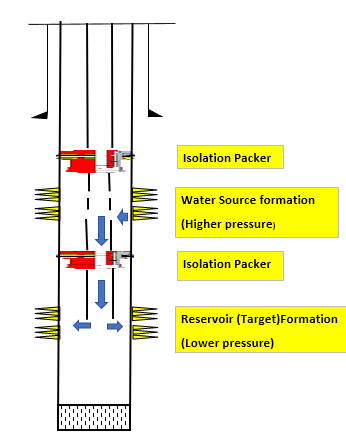
Natural dump flooding has many limitations, as injection pressures uncontrolled and also injection rates. Injection pressures difference and rates decrease with time (as reservoir pressure increase and depleted water bearing formation) (9).
2.3. Power dump flood technology
PDF is downhole water injection system. It supports reservoir pressure for depleted reservoirs.it uses E.S. pump (with special design) to inject water (supplied from aquifer formation) with required rate to reservoir formation. Water flooding increase reservoir pressure to return it back near its initial value and try to keep at this level by voidage replacement (10).
By using different sizes of E.S. Pump, we can inject the target rates for the reservoir and support reservoir pressure. Injection process by PDF is considered as closed system due to injection is in the same well from source formation (aquifer) to target formation (reservoir).
2.3.1. Power dump flood components
2.3.1.1. Electric submersible pump
The Electric Submersible Pumping (ESP) System is one of primary recovery methods. ESP is one of artificial lift systems that used to produce large oil volumes and transfers electrical energy from the surface to a down hole motor that converts it into a mechanical force(torque). This rotational movement turns the pump’s impellers and lifts the well fluids to the surface (11). ESP pumps (centrifugal pump) is a machine that moves fluid by spinning it with a rotating impeller in a diffuser that has a central inlet and a tangential outlet. The pressure (head) develops against the inside wall of the diffuser because the curved wall forces fluid to move in a circular path and converting velocity head to (pressure) head.
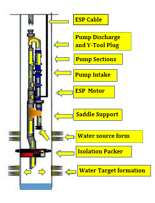
Figure 2 shows the components of electric submersible pump and its ordering. ESP Motor drives the downhole pump by converting electrical energy into mechanical energy which will rotate pump shaft that connected to the motor shaft. Protector section connects motor shaft to pump intake to isolate motor oil from formation fluid, equalization for pressure between inside and outside motor, allow expansion and contraction of motor oil, and absorption the thrust load of the pump.
Pump intake is the entry for well fluid to the pump from annulus. Centrifugal pump is multistage sections. Each stage consists of impeller, shaft &diffuser. the impeller rotates around the pump axis and give centrifugal force to the well fluid then to diffuser which turns fluid velocity into head and move to next stage (12). Discharge head is end of pump section which transfer fluid from inside the pump to the tubing. ESP cable transfer power from surface source to the downhole motor. It is designed flat or round. It consists of copper, insulation, jacket and metal armor. It is very important to avoid system failure (short circuit).
2.3.1.2. Y-tool and isolation packer
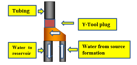
Isolation packer isolates anulus between source formation and reservoir formation and by this prevent connecting formation water with reservoir before its pressure increase through ESP pump. Y-tool block is one of the most critical components in the system and consists of Saddle block, swivel nipple, Y-tool plug and By pass assembly. Figure 3. appears Y-Tool plug importance as it prevents water out of discharge head of ESP pump (with the required high pressure and rate) from moving upward the tubing and force it to by-pass joints to move downward and injected in reservoir formation.
2.3.1.3. Surface Equipment
Junction box is the main contact point between the downhole cable and the surface cable. It is used to check faults of down hole or surface cable and vent gases to atmosphere that escape through the cable insulation to prevent fire or explosions.VSD (Variable speed drive) is connected to transformer.it allows fine tuning for electrical frequency so increase efficiency and minimize unit cycling. It provides soft starts to the unit which reduces system stresses, Protects the downhole equipment from current as well as voltage unbalance and adjust them to well condition so increase ESP run life. Transformer converts the supply voltage to the required system voltage. It is flexible for multiple tap and designed to be greater than the required total KVA for downhole system. SCADA system connected to down hole sensors and transfer data to operators. X charismas tree at surface of the well.
2.3.2. PDF Work method
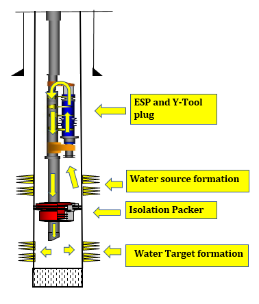
Figure 4. represents the system technique, Water is supplied from source formation to the wellbore then to pump intake at ESP system. ESP system increases the pressure and rates to the required for injection. Water is forced toward injection (reservoir) formation by using Y-tool that prevents water moving upward across the tubing by plug. Then Water moves downward to target(reservoir) formation by high discharge pressure from E.S. pump system. Isolation packer (between aquifer and reservoir formation) prevents injected water from moving upward the anulus.
The high-pressure forces water to enter the target formation and sweep oil toward oil well. This is achieved by voidage replacement as replacing volume of produced fluids (gas, oil and water) from reservoir by injected water and the ratio between barrels of produced fluids to injected fluid is ratio of voidage replacement (13). Injected water with the required rate and pressure will support reservoir pressure and increase it so stop decline in production and resume it to economic rates.
2.3.3. Power system optimization
The system needs power to start up, running ESP and all its component. This power may be supplied from diesel generators, electrical power grid or renewable energy sources. Diesel generators have many problems as high carbon emissions and air pollution .Also diesel generators cause many down times for oil and gas wells and this will reduce its production and lead to short run life for ESP systems as many start and stop for ESP systems(High electrical load at start cause damage of electrical cables which transfer power from surface to down hole ESP motor and so need system to be replaced).Diesel generators consumed large quantity of diesel and so high cost .
Because of these problems and power optimizations, replaced diesel generators by Power from National Power Grid which is running with renewable energy (solar, wind, hydroelectric) and clean energy. Transferred electrical power from electrical substation through power cables to oil and gas fields. Then (according to power design) to electrical cells, RMU units (remotely main units), Number of electrical transformers, digital meters for power consumption, connecting and disconnecting electrical boxes, Many VSD, Scada systems, switch panels and to Down hole ESP.
Simulation for challenging during commissioning and start up enable us for the best approach to start up and safe operation. Artificial intelligence and digitalization through systems (RMU, digital meters, SCADA systems…etc) lead to close monitoring for measurements, defects and predictive analysis so reduce down time for wells and process. Risk management and HSE workplace improved by reduction of loading and unloading many diesel generators, maintenance equipment, avoid diesel soil pollution (especially in agriculture area) and reduction trips number for maintenance and to check scattered diesel generators.
3.Results and advantages
We have Sandstone depleted reservoir which its pressure decreased from 2800 to 1000 psi. Production decreased by more than 75% and primary recovery methods cannot resume required production. Application of surface injection will need time and high cost. Source water formation existed and have compatibility with reservoir formation. Also, Natural dump flood has problems of uncontrolled pressures and rates. We need to resume high production or we will shut in field. By study geology of area and re-evaluate formations lithology found source formation above reservoir formation and is not connected with reservoir. We used PDF systems to get water from source formation and injected to reservoir formation.
We used PDF system to inject 2000 BwPD to target formation with ESP pump discharge 2600 psi. Table 1 show production of each oil well affected by PDF system before application and after it.
Table 1. Oil wells production before PDF and After PDF
|
Well |
Before PDF |
After PDF |
|
W2 |
20 BoPD |
63 BoPD |
|
W202 |
43 BoPD |
476 BoPD |
|
W210 |
15 BoPD |
175 BoPD |
|
W211 |
132 BoPD |
131 BoPD |
|
W212 |
214 BoPD |
171 BoPD |
|
W213 |
147 BoPD |
408 BoPD |
As can be seen from Figure 5, The use of PDF technology for water injection at sandstone depleted reservoir has positive effect on production.
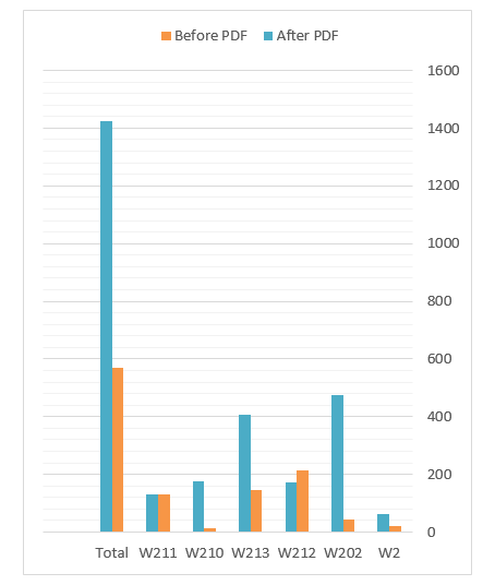
By application Water injection with PDF technology, the reservoir pressure increased from +/- 1000 psi to about +/- 2200 psi (more than twice). The water injected (+/-2000 BwPD) to reservoir with pressure (+/- 2600 psi) cause voidage replacement for oil with water. This supported reservoir pressure and increased it from (1000 to 2200 psi) which caused more oil displacement from reservoir pore spaces. And so, swept more oil from reservoir toward production wells which led to increase production of each well that affected by the use of PDF technology for water injection as shown in figure 5. Total wells production increased from 570 BoPD to +/- 1424 BoPD which means we have gain about +/- 850 BoPD. Application of PDF systems to depleted reservoir improved production by 2-3 times rather than before and this provides good impact on budgets and investments for oil companies.
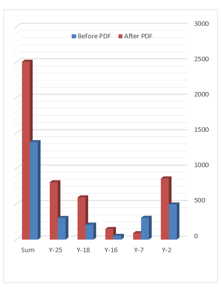
Another Example for sandstone depleted reservoir, the reservoir pressure decreased from (+/- 3000 psi) to (+/- 900 psi) and production decreased by more than 65%. We used two PDF systems to inject (+/-3700 BwPD) to target formation with ESP pump discharge (+/-3500 psi). Oil wells production before and after the use of PDF technology are shown in Table 2.
Table 2. Oil wells production before PDF and After PDF
|
Well |
Before PDF |
After PDF |
|
Y-2 |
496 BOPD |
863 BOPD |
|
Y-7 |
308 BOPD |
91 BOPD |
|
Y-16 |
54 BOPD |
150 BOPD |
|
Y-18 |
211 BOPD |
596 BOPD |
|
Y-25 |
396 BOPD |
809 BOPD |
By the use of Water injection with PDF technology, the reservoir pressure increased from +/- 900 psi to about +/- 2300 psi (more than twice). The water injected (+/-3700 BwPD) to reservoir with discharge pressure (+/- 3500 psi) cause voidage replacement for oil with water. This supported reservoir pressure and increased it from (900 to 2300 psi) which caused more oil displacement from reservoir pore spaces. And so, swept more oil from reservoir toward producer wells which led to increase production of each well that affected by the use of PDF technology for water injection as shown in figure 6.
For well Y-7 at Table 2. It showed decrease in production from (308 to 91 BoPD), this is due to the well showed early low permeability and so performed highly hydraulic fractured (Before PDF application). After PDF technology applied, the well showed early water breakthrough and so water cut increased rapidly which led to decrease its oil production. But as can be seen from Figure 6, the total field production increased from 1395 BoPD to +/- 2509 BoPD which means we have gain about +/- 1114 BoPD. Application of PDF systems to depleted reservoir improved production and approximately double it rather than before.
But as all water injection techniques, carful should be taken before application and study well applied reservoir properties, lithology, rock fluid properties, wettability, water oil mobility to avoid water breakthrough or not improve in production. Generally, if you have depleted reservoir and will apply water injection, the best technique is PDF technology.
3.1.PDF More suitable from environmental and safety policies point of view
Environmental and safety policies is the most critical item in oil industry and no exceptions in it. Application of this technology have good impact on that as it eliminates surface injection water line problems, like leakage and holes which resulting from corrosion (accompanied to surface water injection stations). Avoiding the use of sea and river water in injection operation which preservers marine and river ecosystems. Soil pollution problems are avoided which resulting from leakage or cracks in injection lines that are very critical especially in agriculture area. Less environmental problems (like overflow from tanks, corrosion in surface facility) as injection system is closed in same well.
Also Averting chemical injection problems with surface injection facility resulting from chemical hazards. These hazards may lead to accident or death. Source power problems were avoided from diesel generators (like high carbon emissions, soil and noise pollutions) which is needed for surface facility and running the system. Cancelled a lot of trips for operation activities to check the injection lines and facility (sometimes unsafe, dangerous or very difficult in bad weather).
Less risk assessment from surface injection facility and fabrication injection lines as no need for it. It Eliminates hazards of transferring water to surface injection facility like truck accidents and soil pollution problems. Also, eliminates hazards of work, movement, loading and unloading equipment inside surface injection facility which may lead to accidents and fatal.
3.2. Production improvement
The PDF technology resumes high production and improves it (2- 3 times) due to supporting reservoir pressure very fast, reduction of time to fill up reservoir. It accelerates starting water injection project by saving time of construction surface injection facility, lines and drill injection wells. So, all of this increase production at short time which cause more money and profits for shareholders.
It gives flexibility to control injection rates and pressure as VSD on surface control ESP pump parameters, so increase or decrease the injection rates and pressures to injection targets. SCADA system enable us from remotely monitoring through online and accurate recording for a lot of data by downhole sensors (like pump intake, discharge, temperature...etc). All of this give better study for water injection system and reservoir, so correct decisions for improving production.
3.3. High cost saving for CapEx and OpEx
The system saves a lot of capital and operation cost for companies. As no large surface areas is needed for injection system (only one well for injection system) and this very important especially at agriculture, populated areas or offshores. It Saves cost of surface injection facility (consist of tanks, pumps and pipelines) and injection lines (No need for it) which is at least (+/- 3) million dollars for one simple facility. Saving drilling injection wells which is about (+/- 4) million dollars per well and high cost of diesel which is required for running the system and surface facility (+/- 7 million dollars/year). Avoided high cost of transportation water from source wells to surface facility (Trucking and lines if onshore or agriculture area).
Reduction cost of environmental agreements and government permissions especially in Agriculture, offshore or residential area. The chemical cost (very expensive) is lower than the surface injection facility (as PDF is closed system in one well). It is Remotely monitoring so reduce cost and need of manpower, cost of hazard operation and risk assessment studies as no surface injection facility.
3.4. Other advantages
Water incompatibility problems are avoided as source formation and reservoir formation water are compatible and injection is done in same well. Water incompatibility leads to serious problems like scale formation at down hole or surface injection lines and facility. Scale formation can cause plugging perforations or block reservoir pores and so decrease production. PDF is more suitable as gas is not available for injection or low amounts at fields.
4. Conclusions
Low production of oil fields at depleted reservoirs, High carbon emissions from diesel engines and generators, climate change, high cost for Opex and Capex are the most critical challenges for petroleum companies. Water injection improve production of depleted reservoirs. Surface water injection facility have problems of high cost and water compatibility. Injected pressures and rates can not be controlled by Natural power dump flood technique. Through application of PDF technology for water injection and running by clean energy sources, all these problems and challenges reduced or avoided.
The results of applying PDF systems at scattered depleted reservoirs achieved increase production by (2-3 times) and saved more than (+/-50) million dollars from fields development.PDF technology is more economic than surface injection facility, better reservoir management than natural dump flood, rapidly resuming target production and more save Opex and Capex budgets. It is recommended for fields with limited space such populated, offshore and agriculture areas and more suitable for environmental and safety policies. It is suitable for digitalization and artificial intelligence technology by connecting through Scada system and electronic sensors. The world is moving rapidly towards reducing carbon emissions and net zero carbon emissions, and it still needs energy from petroleum to cover the high daily needs of it. This technology and optimization power of it offers one of solutions to that.

References
[1] Haiyang, S., Longxin, M., Haiying, H., Yongge, L., Bo, L. (2015)"Development mechanisms and influencing factors of dump flooding.Petroleum Exploration and Development" pp 42, 5, 691-696. View Article
[2] John, F., Cook, M., and Graham, M. "Hydrocarbon Exploration and Production" Elsevier Science, Vol. 55, 2 Edition, March 2000.
[3] Subhi, H., Rashidi, A., Dey A., Salmi, F., Aisary, M., (2011) "Enhancement of oil recovery through Dump-flood water injection concept in satellite field" Paper SPE 142361-MS, SPE Conference Paper, 6 pages, SPE Middle East Oil and Gas Show and Conference held in Manama, Bahrain,25- 28 September, Society of Petroleum Engineers.
[4] Tarek,A. (2006) "Reservoir engineering handbook. Chapter 14. Principles of Waterflooding, pp 909-1095, Elsevier, Gulf Professional Publishing. View Article
[5] Willhite, G.P. (1986)" Waterflooding" SPE Textbook Series, Vol. 3, Society of Petroleum Engineers. View Article
[6] Charles, Patton., "Oil field water systems " 2nd Edition.,pp 175-180 ,November 1981.
[7] Mahmoud, A., Khayami, A., Mansoor M., Buasali M. (2019)" Integrated Reservoir Study to Maximize Oil Recovery by Optimizing Shuaiba Dump Flooding into the Kharaib Reservoir" Abu Dhabi International Petroleum Exhibition and Conference, Abu Dhabi, UAE, 11-14 November 2019, Society of Petroleum Engineers. View Article
[8] Villarroel, A.J., Nieto Mino, M.D., Estrella, K.I., Perez, J.A. (2015) "Methodology of feasibility study on pilot test for dump flood comletion system" Paper SPE 177039-MS, 27 pages, SPE Latin American and Caribbean Petroleum Engineering Conference, 18-20 November, Quito, Ecuador, Society of Petroleum Engineers.
[9] Abdulhadi, M., Tran, T., Chin, H.V., Suggust, A.A., Usop, M. Z., Zamzuri, D., Dolah,K A., Abdussalam, K., Munandai, H., Yusop Z. (2019)" A Value Driven Approach for Implementing a Simple and Low-Cost Natural Dump-Flood in an Offshore Environment: Lessons Learned from the First Successful Natural Dump-Flood in Malaysia" Paper SPE 194659-MS, 13 pages, SPE Oil and Gas India Conference and Exhibition, Mumbai, India, 9-11 April 2019, Society of Petroleum Engineers. View Article
[10] Rose, S.C., Buckwalter, J.F., Woodhall R.J. (1989) "The Design Engineering Aspects of Waterflooding" SPE Monograph Series Vol. 11, Society of Petroleum Engineers.
[11] Bearden,, J., "Electrical Submersible Pumps, Petroleum Engineering Handbook" Published By SPE, Vol. 4, 1" Edition, August 2007, pp 5-7, 2007.
[12] Baker Hughes Centrlift., "Submersible Pump Handbook". 8th Edition, Claremore, Oklahoma, PP 31-75 ,2009.
[13] Kim, T.W., Vittoratos, E., Kovscek, A.R. (2019)" Recovery efficiency of a 28°API crude-oil system as a function of voidage replacement ratio" Journal of Petroleum Science and Engineering, Volume 175, pp 1063-1087. View Article