Journal of Fluid Flow, Heat and Mass Transfer (JFFHMT)
ISSN: 2368-6111

Volume 10 - Year 2023 - Pages 69-77
DOI: 10.11159/jffhmt.2023.010
Comparison of Hybrid Cooling Concepts with PCM Cooling for Electric Battery Packs
Seham Shahid1, Martin Agelin-Chaab1
Faculty of Engineering and Applied Science
1Ontario Tech University
2000 Simcoe Street North, Oshawa, Canada
Seham.shahid@ontariotechu.net; martin.agelin-chaab@ontariotechu.ca
Abstract - In this paper, a hybrid thermal management strategy is proposed to increase the temperature uniformity and improve cooling within a Lithium-ion battery pack. Three different configurations are developed and compared. In all three configurations, the phase change material is placed directly with the cells, and liquid channels are placed in the battery pack to extract heat from the phase change materials. Furthermore, an air duct is placed at the top of the battery to extract heat from the fluids that are stationary within the liquid channels. In the first configuration, the liquid channels are placed in between the phase change material. In the second configuration, the location of the liquid channel is changed such that a part of it is in direct contact with the cells. This configuration is then modified for the third configuration such that for every three cells, there are two liquid channels. A baseline battery pack is also developed which contains only PCM cooling. Transient numerical studies were conducted, and the results indicated that through the first configuration, the maximum temperature was limited to 31.5 °C and the temperature uniformity to 1.75 °C. Moreover, this strategy does not require excessive pumping fluid power and high air velocities, which implies that less energy is required for the operation of the thermal management system.
Keywords: Phase change material, hybrid cooling, liquid channels, battery thermal management, computational fluid dynamics analysis, lithium-ion cylindrical cells.
© Copyright 2023 Authors - This is an Open Access article published under the Creative Commons Attribution License terms Creative Commons Attribution License terms. Unrestricted use, distribution, and reproduction in any medium are permitted, provided the original work is properly cited.
Date Received: 2023-06-05
Date Revised: 2023-07-11
Date Accepted: 2023-07-20
Date Published: 2023-08-28
1. Introduction
Greenhouse gas emissions and their adverse effects on the environment are challenging phenomena. An attempt is made to avert its impact through the electrification of the transportation industry. Electric vehicles (EVs) are gradually penetrating the transportation industry and gaining market share. The primary source of power within the EVs is through the electric battery packs, and currently, Lithium-ion (Li-ion) cells are the main candidate for storing and providing electric energy within these battery packs. The advantage of Li-ion cells is that they have no memory effect, high power and energy densities, a long lifecycle, and a low rate of self-discharge [1]. On the contrary, Li-ion cells require a highly effective thermal management system (TMS) to maintain the specific thermal conditions required for their optimal performance [1].
The cooling medium within the TMS is composed of either air, liquid, and phase change material (PCM) or a combination of these mediums. The air-based TMS is lightweight and cost-effective, however, the low thermal conductivity and heat capacity hinders its use in large battery packs required for the operation of the EVs [2]. Researchers have studied multiple battery packs and cell arrangements in order to maximize the potential of air-based TMS. The study by Yang et al. [3] and Fan et al. [4] concluded that an aligned structure of cylindrical cells provided an improved thermal performance compared to a staggered structure. Additionally, to improve temperature uniformity within the battery pack, a reciprocating airflow was introduced by Mahamud and Park [5]. Moreover, the author’s previous studies introduced inlet plenums, vortex generators, and jet inlets to increase mixing and turbulence with the airflow stream to maximize the heat extracting capacity of air [1].
Liquid-based TMS is widely used within the industry due to the increased heat extraction capabilities of the fluids. However, the pumping power required for the continuous flow of fluids reduces the power availability to propel EVs [6]. A liquid-based TMS utilizes either an electrically insulating fluid or an electrically non-insulating fluid. The electrically insulating fluid is used in strategies where the fluid is required to be in direct contact with the surface of the cells. These fluids have high viscosities, which directly impact the pumping power requirement of the TMS. Moreover, in large battery packs, the risk of fluid leakage increases [7]. In contrast, strategies were developed by incorporating cold plates in the TMS. The cold plates are placed in direct contact with the surface of the cells, and the fluid flow through liquid channels within these cold plates. These strategies allow the flexibility of using electrically non-insulating fluids. Currently, cold plate-based strategies are applicable to prismatic cells because of less design complexity and manufacturing difficulty compared to cylindrical cells [8].
PCM-based TMS is highly effective in maintaining temperature uniformity within the battery pack. The use of PCM was initially proposed by Al-Hallaj and Selman [9]. The PCM uses its latent heat to absorb the heat from the cell’s surface and keep the temperatures within the phase change temperatures of the PCM [10]. A comparison was made by Jiang et al. [11] between the use of the PCM and forced air in the TMS. The results concluded that with 5 C discharge rate, the maximum temperature reached 72 °C with forced air cooling and 41 – 44 °C with PCM. The PCM that was used was a combination of expanded graphite and paraffin. The temperature uniformity with PCM was also investigated, and it was maintained within the range of 1 – 2 °C. According to He et al. [12], the optimum amount of expanded graphite with the composite PCM was 7 %. The challenge with PCM is the incorporation of secondary cooling medium to increase the overall heat transfer ability once the latent heat is all used up. This limits its use within EVs [13].
Due to the drawbacks of individual cooling mediums, researchers have developed hybrid TMS, which involves multiple cooling mediums in a single system. An instinctual strategy is to add water mist into the airflow to increase heat extracting capacity. Saw et al. [14] conducted a study using mist cooling to keep the surface temperatures of the cell below 40 °C, and it was concluded that to achieve the desired results 3 % of mist, a 5 g/s mass flowrate is needed. Additionally, Wei and Agelin-Chaab [2] investigated the evaporative and convective heat transfers by placing hydrophilic liquid strips in the airflow channels. Through the use of hydrophilic liquid strips, the water was extracted from the reservoir using capillary action. Using natural evaporation and convection, the heat from the airflow was removed using the liquid strips. This increased the heat extraction capacity of the airflow for the latter cells within the battery pack resulting in a 56 % increase in the temperature uniformity and 20 % increase in the cooling of the cells. In a previous study [13], the authors developed a hybrid TMS by attaching liquid jackets to each of the cylindrical cells. Since each cylindrical cell had a separate liquid jacket, therefore, water with a high thermal conductivity was used in direct contact with the surface of the cells. This allowed increased cooling and improved temperature uniformity of 1.26 °C. Moreover, jet inlets and vortex generators developed in earlier research [15] were incorporated to increase turbulence and mixing within the airflow to achieve the desired results.
The present research builds upon the established knowledge provided in a literature review. A hybrid TMS strategy is proposed by combining air, liquid, and PCM mediums. Three battery pack configurations are developed and compared. The primary objective is to maintain the cell temperatures within 40 °C and the temperature uniformity within 5 °C. The secondary objectives are to minimize the required amount of PCM, reduce the pumping power required for airflow and eliminate the continuous pumping power of fluids.
2. Methodology
2.1. Hybrid TMS Proposed Battery Packs
The proposed battery packs include nine 18650 cylindrical Li-ion cells [1]. The cathode material of the cell is LiNiMnCoO2, and the anode material is graphite. Each cell has a capacity of 2.5 Ah, and a nominal voltage of 3.6 V. A visual representation of the proposed strategy is provided in Figure 1. This strategy consists of three stages of cooling. In the first stage, the cell generates heat which is absorbed by the PCM material that surrounds each cell. In the second stage, there are liquid channels that run through the PCM material, which extracts heat from the PCM. Finally, in the third stage, through natural evaporation, the evaporated fluid goes into the air duct placed at the top of the battery pack, and the airflow expels the heat from the fluid (evaporated fluid) into the environment. It is to be noted that fluid in the liquid channel stays stationary, and continuous pumping power is not required. The properties of air, water, and PCM are provided in Table 1.
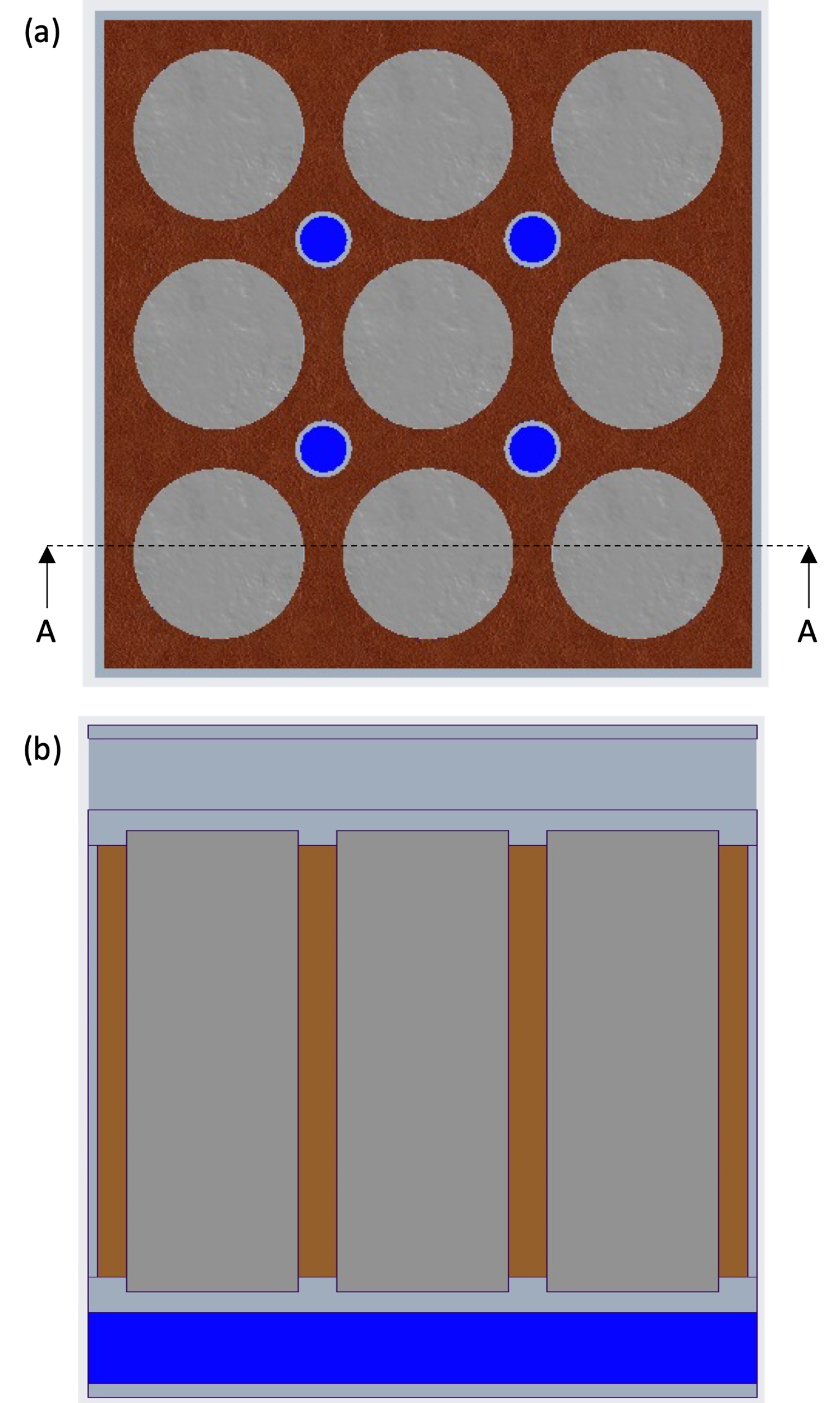
Table 1: Material properties of air, water, and PCM.
|
Material Properties |
Air |
Water |
PCM |
|
Density (kg/m3) |
1.225 |
998.2 |
880 |
|
Specific Heat (J/kg.K) |
1,006 |
4,182 |
2,150 |
|
Thermal Conductivity (W/m.K) |
0.0242 |
0.6 |
0.21 |
|
Solidus Temperature (K) |
58 |
273 |
303 |
|
Liquidus Temperature (K) |
61 |
273 |
305 |
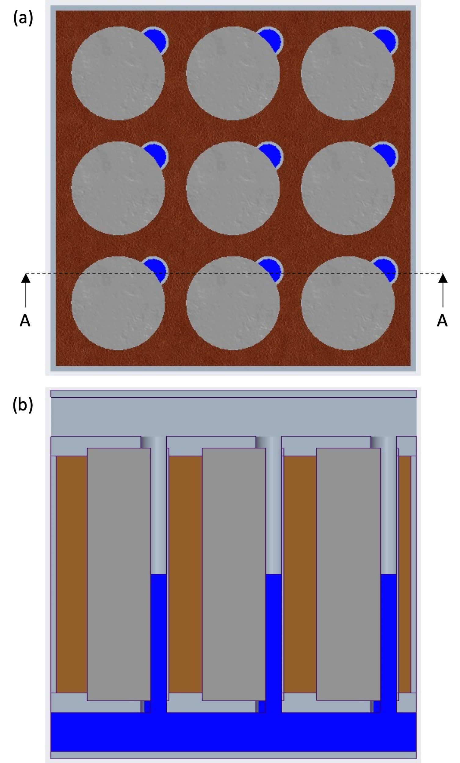
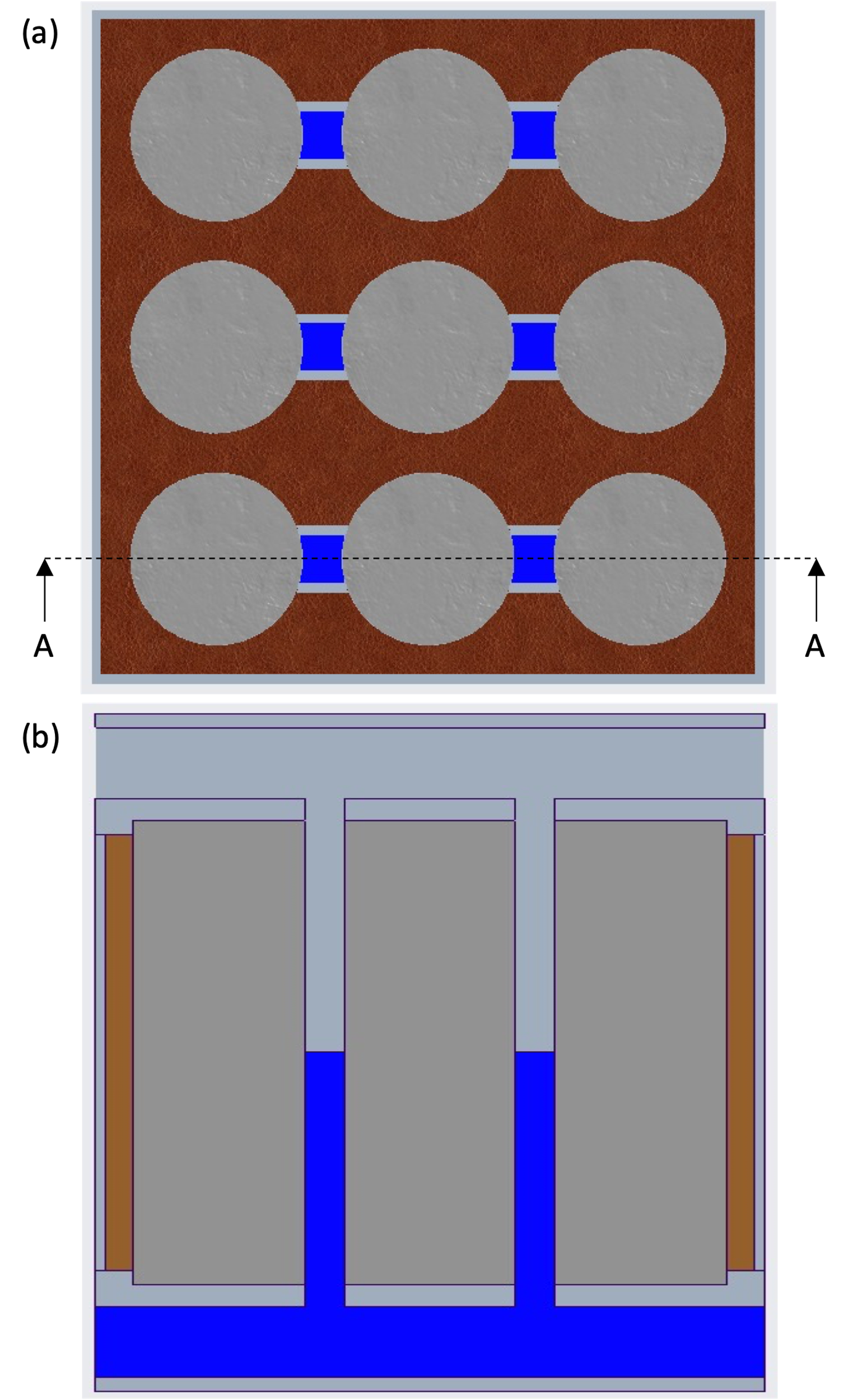
Three distinct battery pack configurations are developed for this study. In all three configurations, the PCM surrounds the cells and is in direct contact with the surface of the cells. An outer case of the battery pack ensures that the PCM stays within the bounds of the battery pack. An air duct is placed at the top of the cells, and a liquid reservoir is placed at the bottom of the cells. The computer-aided design (CAD) model for Pack-1 is shown in Figure 1. The liquid channels in this configuration are placed in between the PCM material and run vertically from the liquid reservoir to the air duct. The CAD model for Pack-2 is shown in Figure 2. In this configuration, the location of the liquid channel is modified. A portion of the liquid is connected directly to the cells. The rest of the portions are connected to the PCM. This concept allows the liquid to extract heat from the cell and the PCM simultaneously. The CAD model for Pack-3 is shown in Figure 3. The liquid channels are simplified by connecting them from one cell to the subsequent cell. This is a simpler form of Pack-2 and should allow enhanced heat transfer from the cell to the liquid and the PCM as well. Finally, a baseline pack was developed by using PCM only as shown in Figure 4. For comparison, the volume of liquid used in all three instances was kept the same by modifying the dimensions of the liquid channels.
2.2. Numerical Modelling
Numerical modelling was conducted using ANSYS Fluent for the battery packs proposed in Section 2.1. It was achieved through the coupling of the solidification/melting (PCM), energy, and flow models. Turbulence modelling was not included as the flow within the air duct was considered laminar. The governing equations for the energy and flow models are shown below [16].
Energy Equation:

Continuity Equation:
Momentum Conservation Equation:
where;

For the PCM region, the solidification/melting model is used to enable the change in phase using the latent heat between defined temperature boundaries. To model the phase change, an enthalpy-porosity technique is employed. In this, a liquid fraction (B) quantity is used, which tracks the fraction of each cell that is in liquid form. This is based on the enthalpy balance. The energy equation for this model is as follows [16].

The mesh was developed using the ANSYS Meshing software. A combination of unstructured tetrahedral and hexahedral mesh was developed. Hexahedral mesh was used for the cell region and tetrahedral mesh was used for all the other battery pack regions. The inflation layers were created near the walls of the air duct only to capture the boundary layer of the airflow. A mesh independence study (MIS) was performed to ensure that the results were independent of the size of the mesh. Based on the MIS, the chosen mesh consisted of 614,024 elements. Additionally, a time independence study (TIS) was performed to ensure that the results are independent of the size of the time step. Based on the results of the TIS a time step size of 0.5 s was selected.
Transient simulations were performed to accommodate the phase change phenomenon. The ambient conditions for all the battery packs were set to 20 °C at atmospheric pressure. The inlet airflow velocity was based on the Reynolds number of 1950 and was set to 1.65 m/s. The transient heat generation profile of the Li-ion 18650 cell was obtained at a 2 C discharge rate through the experimental study conducted in the author’s previous research [1]. The heat generation equation applied as a boundary condition at the surface of the cell was obtained by curve-fitting of the experimental profile and is shown below.

3. Results and Discussion
3.1. Numerical Model Validation
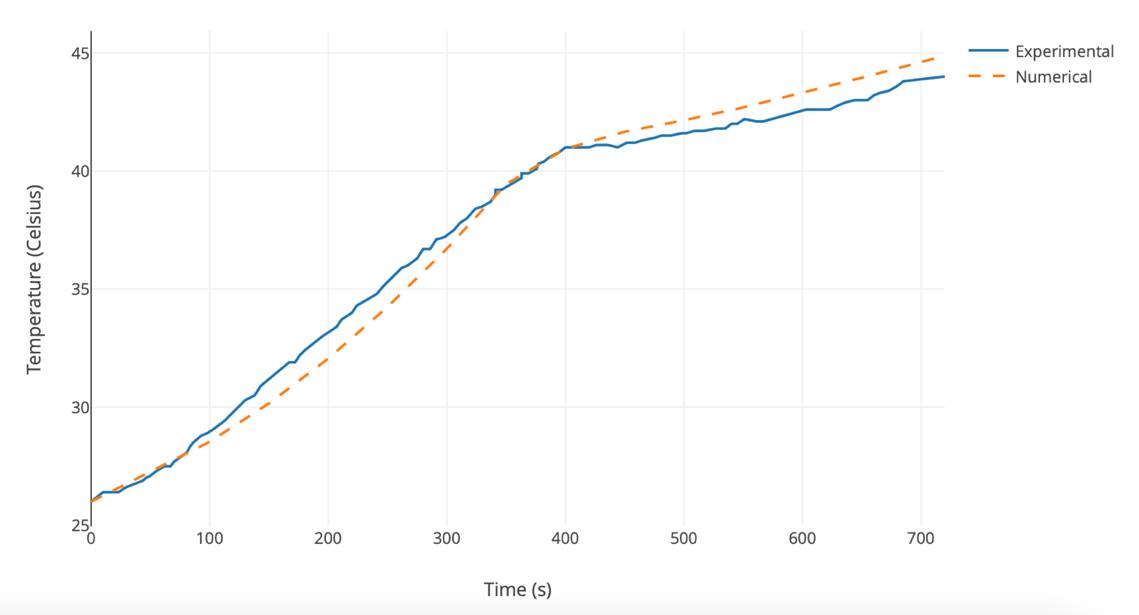
The developed numerical model was validated using the experimental study and results provided by Jiang et al. [17]. The same experimental setup and conditions were recreated to validate the model. The results are shown in Figure 5. The numerical results follow the experimental results closely. The variation stays within 1 °C, which agrees with the model validations in the open literature [17]. Therefore, the results of the numerical model agree with the experimental results, and the model is considered validated.
3.2. Thermal Analysis
In order for the Li-ion cells to perform effectively, the maximum temperature of the cells needs to be maintained below 40 °C and the temperature uniformity below 5 °C. Temperature uniformity is a measure of the difference between the maximum and minimum temperatures of the cells. As the temperature difference decreases, the temperature uniformity increases and vice-versa. The maximum and minimum temperatures with respect to time for all the battery packs are provided in Figure 6. Additionally, the temperature contours at the end of the discharge cycle for all the battery packs are provided in Figure 7.
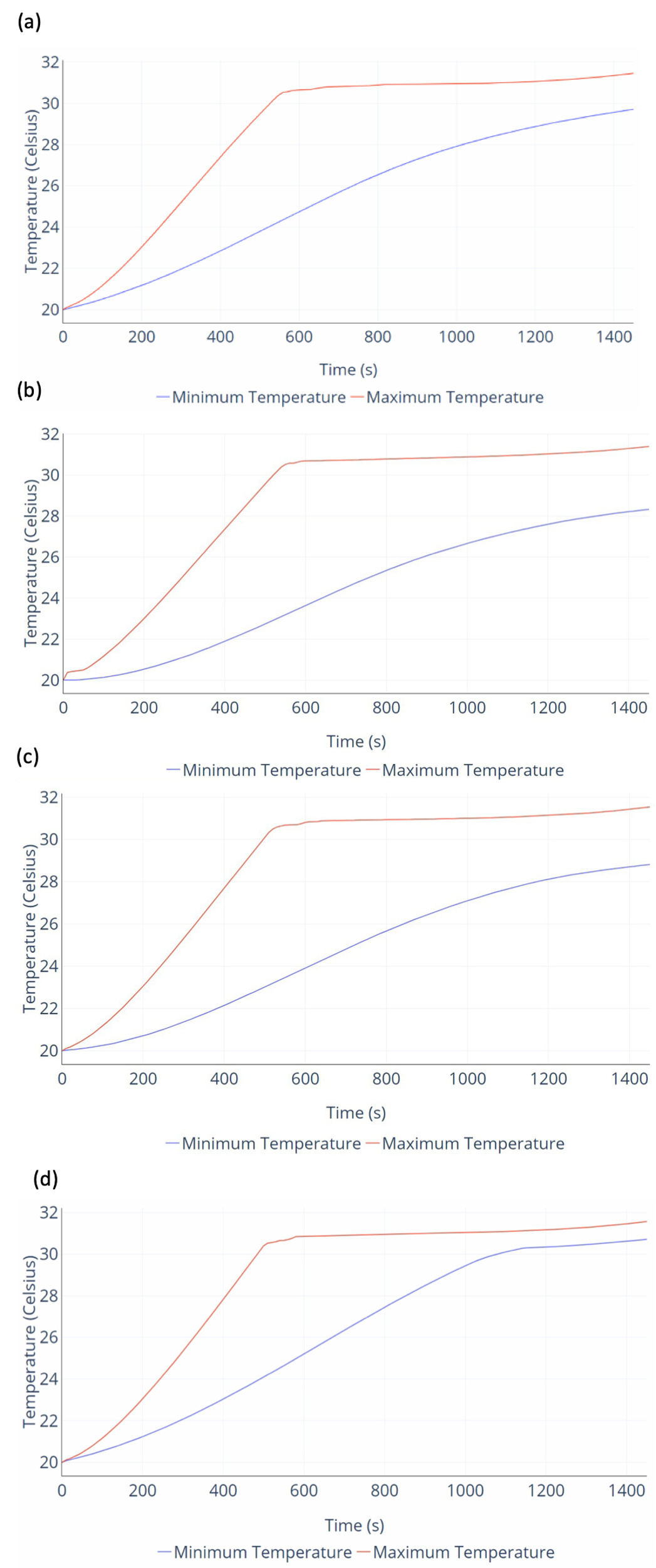
As shown in Figure 6, in all the battery packs the maximum temperature of the cells is limited by the phase change temperature of the PCM material, therefore, the temporal curve of maximum temperature is almost identical. Once the phase change temperature of the PCM is reached at ~500 s, then the maximum temperature curve flattens out, and the temperature is maintained. The minimum temperature in Pack-1 is higher than the minimum temperatures in Pack-2 and Pack-3. This is because, in Pack-2 and Pack-3, the minimum temperature occurs in the region where the cell is in contact with water. Due to the higher thermal conductivity and specific heat capacity of water low temperatures are observed. The airflow with the duct allows the air to extract some of the heat from water as well, which increases the heat extraction capacity of water, allowing more heat transfer from the surface of the cell that is in contact with water. The reduced minimum temperature in Pack-2 and Pack-3 results in a decrease in the temperature uniformity, as shown in Figure 8. Moreover, since there is no liquid cooling and air cooling in the baseline pack, therefore, the minimum temperature curve for the baseline pack shown in Figure 6d also reaches the phase change temperature at approximately 1,100 s. Any heat generated by the cells beyond this is extracted through the latent heat of the PCM. The temperature uniformity is highest at this point since there is minimal gap between the maximum and minimum temperature curves. However, this high temperature uniformity is achieved at the cost of increased PCM usage and melting.
Additionally, from Figure 7a it can be seen that in Pack-1 the surface of the cells in facing the neighbouring cells have higher temperatures, whereas the surface of the cell facing the battery pack housing and liquid channels have slightly lower temperatures. Moreover, in Pack-2 (Figure 7b) and Pack-3 (Figure 7c) it can be seen that the surface of the cell in contact with water has the lowest temperatures as discussed earlier.
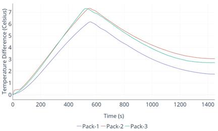
It can be seen from Figure 8 that the temperature uniformity in all three battery packs decreases until the temperature reaches the point where the phase change of the PCM begins. At this point, the maximum temperature is limited, however, the minimum temperature of the cell keeps on increasing, which reduces the temperature difference. This then allows the hybrid TMS to increase the temperature uniformity of the battery pack. Moreover, the highest temperature uniformity is exhibited by Pack-1 when compared to Pack-2 and Pack-3.
Finally, the amount of PCM that was converted into liquid was extracted from the numerical results. The liquid fraction was 6.13 % for Pack-1 and 5.93 % for Pack-2 and Pack-3. Since some of the heat from the surface of the cells was directly extracted by the fluid in Pack-2 and Pack-3, therefore, a slight decrease in the liquid fraction percentage was exhibited. However, due to a hybrid design by which water and air extract heat from the PCM, a low usage of approximately 6 % is achieved. In comparison, the liquid fraction for the baseline pack was 10.33 % due to no secondary cooling circuits available.
4. Conclusions
This study examines the issue of Lithium-ion cell cooling and temperature uniformity. A hybrid strategy is developed by combining the air, liquid, and phase change material mediums. A novel design is proposed in which the cells are surrounded by phase change material, and liquid channels are added to allow the extraction of heat from the phase change material. Additionally, an air duct is added to allow the airflow to extract heat from the fluid in liquid channels. Three different battery pack configurations are developed and compared using numerical simulations. In the first configuration, the liquid channels were placed in between the phase change material. In the second configuration, a portion of the liquid channel was directly in contact with the surface of the cells. In the third configuration, the second configuration was modified by adding two liquid channels for three cells. A baseline pack is also developed with PCM only for comparison purposes. The numerical model is validated from experimental results in the open literature. According to the results, the maximum temperature was maintained at approximately 31.5 °C in all three configurations, however, the highest temperature uniformity of 1.75 °C was exhibited by the first configuration. Therefore, the thermal performance requirement of maintaining the maximum temperature below 40 °C and temperature uniformity within 5 °C was achieved with minimal fluid pumping requirements as the fluid within the liquid channel is kept stationary.
References
[1] S. Shahid and M. Agelin-Chaab, "Analysis of cooling effectiveness and temperature uniformity in a battery pack for cylindrical batteries," Energies (Basel), vol. 10, no. 8, 2017, doi: 10.3390/en10081157. View Article
[2] Y. Wei and M. Agelin-Chaab, "Development and experimental analysis of a hybrid cooling concept for electric vehicle battery packs," J Energy Storage, vol. 25, no. August, p. 100906, 2019, doi: 10.1016/j.est.2019.100906. View Article
[3] N. Yang, X. Zhang, G. Li, and D. Hua, "Assessment of the forced air-cooling performance for cylindrical lithium-ion battery packs: A comparative analysis between aligned and staggered cell arrangements," Appl Therm Eng, vol. 80, pp. 55-65, 2015, doi: 10.1016/j.applthermaleng.2015.01.049. View Article
[4] Y. Fan, Y. Bao, C. Ling, Y. Chu, X. Tan, and S. Yang, "Experimental study on the thermal management performance of air cooling for high energy density cylindrical lithium-ion batteries," Appl Therm Eng, vol. 155, no. December 2018, pp. 96-109, 2019, doi: 10.1016/j.applthermaleng.2019.03.157. View Article
[5] R. Mahamud and C. Park, "Reciprocating air flow for Li-ion battery thermal management to improve temperature uniformity," J Power Sources, vol. 196, no. 13, pp. 5685-5696, 2011, doi: 10.1016/j.jpowsour.2011.02.076. View Article
[6] S. Shahid, B. Chea, and M. Agelin-Chaab, "Development of a hybrid cooling concept for cylindrical li-ion cells," J Energy Storage, vol. 50, p. 104214, Jun. 2022, doi: 10.1016/J.EST.2022.104214. View Article
[7] S. Shahid and M. Agelin-Chaab, "A review of thermal runaway prevention and mitigation strategies for lithium-ion batteries," Energy Conversion and Management: X, vol. 16, p. 100310, Dec. 2022, doi: 10.1016/J.ECMX.2022.100310. View Article
[8] S. Panchal, R. Khasow, I. Dincer, M. Agelin-Chaab, R. Fraser, and M. Fowler, "Thermal design and simulation of mini-channel cold plate for water cooled large sized prismatic lithium-ion battery," Appl Therm Eng, vol. 122, pp. 80-90, 2017, doi: 10.1016/j.applthermaleng.2017.05.010. View Article
[9] S. al Hallaj and J. R. Selman, "A Novel Thermal Management System for Electric Vehicle Batteries Using Phase‐Change Material," J Electrochem Soc, vol. 147, no. 9, p. 3231, Sep. 2000, doi: 10.1149/1.1393888. View Article
[10] N. Javani, I. Dincer, and G. F. Naterer, "Numerical Modeling of Submodule Heat Transfer With Phase Change Material for Thermal Management of Electric Vehicle Battery Packs," J Therm Sci Eng Appl, vol. 7, no. 3, Sep. 2015, doi: 10.1115/1.4029053. View Article
[11] G. Jiang, J. Huang, M. Liu, and M. Cao, "Experiment and simulation of thermal management for a tube-shell Li-ion battery pack with composite phase change material," Appl Therm Eng, vol. 120, pp. 1-9, 2017, doi: 10.1016/j.applthermaleng.2017.03.107. View Article
[12] F. He, X. Li, G. Zhang, G. Zhong, and J. He, "Experimental investigation of thermal management system for lithium ion batteries module with coupling effect by heat sheets and phase change materials," Int J Energy Res, vol. 42, no. 10, pp. 3279-3288, 2018, doi: 10.1002/er.4081. View Article
[13] S. Shahid and M. Agelin-Chaab, "Development of hybrid thermal management techniques for battery packs," Appl Therm Eng, vol. 186, no. September 2020, p. 116542, 2021, doi: 10.1016/j.applthermaleng.2020.116542. View Article
[14] L. H. Saw, H. M. Poon, H. S. Thiam, Z. Cai, W. T. Chong, N. A. Pambudi and Y. J. King, "Novel thermal management system using mist cooling for lithium-ion battery packs," Appl Energy, vol. 223, no. April, pp. 146-158, 2018, doi: 10.1016/j.apenergy.2018.04.042. View Article
[15] S. Shahid and M. Agelin-Chaab, "Application of jets and vortex generators to improve air- cooling and temperature uniformity in a simple battery pack," J Therm Sci Eng Appl, vol. 11, no. 2, pp. 1-16, 2019, doi: 10.1115/1.4041493. View Article
[17] G. Jiang, J. Huang, Y. Fu, M. Cao, and M. Liu, "Thermal optimization of composite phase change material/expanded graphite for Li-ion battery thermal management," Appl Therm Eng, vol. 108, pp. 1119-1125, Sep. 2016, doi: 10.1016/J.APPLTHERMALENG.2016.07.197. View Article