Journal of Fluid Flow, Heat and Mass Transfer (JFFHMT)
ISSN: 2368-6111

Volume 10 - Year 2023 - Pages 62-68
DOI: 10.11159/jffhmt.2023.009
Comparison between Different PCM Mediums and Dielectric Fluid for Hybrid Thermal Management of Electric Battery Packs
Seham Shahid1, Martin Agelin-Chaab1
Mechanical and Manufacturing Engineering Department
Faculty of Engineering and Applied Science
1Ontario Tech University
2000 Simcoe Street North, Oshawa, Canada
Seham.shahid@ontariotechu.net; martin.agelin-chaab@ontariotechu.ca
Abstract - In this paper, a hybrid cooling strategy for Lithium-ion electric battery packs is developed through the combination of air, liquid, and phase change material mediums. The hybrid strategy consists of the primary cooling medium that surrounds all the Lithium-ion cells and is in direct contact with the surface of the cells. The secondary cooling medium is housed within liquid channels placed in the battery pack to extract heat from a primary cooling medium. Furthermore, an air duct is placed at the top of the battery to extract heat from the fluids that are stationary within the liquid channels. Three distinct concepts are developed to compare the effect of phase change material and liquid medium as the primary cooling medium. In the first and second concepts, the primary cooling medium used is a phase change material, and in the third concept, it is an electrically insulated fluid. The numerical model is validated from experimental results in the open literature. Transient numerical studies were conducted and validated. The results indicate that through the first concept, the maximum temperature was limited to 31.5 °C and the temperature uniformity to 1.75 °C. Moreover, this strategy does not require excessive pumping fluid power and high air velocities, which implies that less energy is required for the operation of the thermal management system.
Keywords: Phase change material, hybrid cooling, liquid channels, battery thermal management, computational fluid dynamics analysis, lithium-ion cylindrical cells
© Copyright 2023 Authors - This is an Open Access article published under the Creative Commons Attribution License terms Creative Commons Attribution License terms. Unrestricted use, distribution, and reproduction in any medium are permitted, provided the original work is properly cited.
Date Received: 2023-06-05
Date Revised: 2023-07-11
Date Accepted: 2023-07-20
Date Published: 2023-08-24
1. Introduction
The transportation industry is one of the major contributors to greenhouse gas emissions. Electrification of vehicles is considered the most promising advancement to avert the impact of the transportation industry on the adverse effects of greenhouse gas emissions. Lithium-ion (Li-ion) cells are the primary source of power in electric vehicles (EVs). Amongst the various cell chemistries, Li-ion cells are highly recommended due to their high energy and power densities, no memory effect, and low self-discharge rate [1]. However, to perform optimally, Li-ion cells require specific thermal conditions which are maintained using a thermal management system (TMS).
The main component of the TMS is the cooling medium which is central to the design of the TMS. The cooling medium consists of either air, liquid, phase change material (PCM), or hybrid medium. Air as a cooling medium is lightweight and cost effective, however, it has a low heat capacity and thermal conductivity, which limits its use in the large electric battery pack required for EVs [2]. Nonetheless, research has been conducted extensively to utilize the advantages of air and maximize its use in the thermal management of cells [3]. Additionally, a reciprocating airflow was introduced by Mahamud and Park [4] to increase the thermal performance of the air based TMS. Moreover, the author’s previous studies introduced inlet plenums, vortex generators, and jet inlets to increase mixing and turbulence with the airflow stream to maximize the heat extracting capacity of air [1].
Compared to air, fluids have higher thermal conductivities and heat capacities, therefore, they are widely used in the current EV market. Liquid based TMS, however, requires high pumping power to move the fluid through the battery pack continuously [5]. There are primarily two categories of liquid based TMS, namely, direct cooling and indirect cooling. In the direct cooling, electrically insulating fluids are used as the fluid is directly in contact with the surface of the cells. These types of fluids have high viscosities, which increase the pumping power required for the operation of the TMS [3]. In indirect cooling, electrically non-insulating fluids are used, which circulate within confined liquid channels that run through the battery pack in various configurations. The liquid channels are in direct contact with the surface and extract heat from the cells. Currently, indirect cooling is limited to the prismatic and pouch cells due to the low complexity in design and ease of manufacturing when compared to cylindrical cells [6].
PCM-based TMS uses the latent heat of PCM to extract heat from the surface of the cells. The PCM is in direct contact with the cells. It is very effective in maintaining the temperature uniformity of the cells in the electric battery pack and maintaining the maximum temperature within the phase change temperature of the PCM [7]. However, the PCM-based TMS requires a secondary cooling system to extract heat from the PCM once the latent heat of the PCM is completely used up, thereby limiting its use within the EVs [8].
In addition to individual cooling mediums, researchers have also studied various combinations of multiple cooling mediums within a single hybrid TMS. Studies have introduced water mist in the airflow to increase the heat extracting capability of the air flow [9]. Additionally, hydrophilic liquid channels have been placed in the path of the airflow to remove the excess heat from the airflow and increase its heat extracting capacity [2]. Moreover, the natural evaporation of water from the liquid channels enters the airflow, which increases the amount of heat that can be extracted from the surface of the cells [2]. In a previous study [8], the authors developed a hybrid TMS by attaching liquid jackets to each of the cylindrical cells. Since each cylindrical cell had a separate liquid jacket, therefore, water with a high thermal conductivity was used in direct contact with the surface of the cells. This allowed increased cooling and improved temperature uniformity. Moreover, jet inlets and vortex generators developed in earlier research [10] were incorporated to increase turbulence and mixing within the airflow to achieve the desired results.
The present research builds upon the established knowledge provided in a literature review. A hybrid TMS concept is proposed, and a comparison is made between the PCM and fluid mediums as the primary cooling medium in the hybrid TMS. The main objective is to maintain the cell temperatures within 40 °C and the temperature uniformity within 5 °C
2. Methodology
2.1. Proposed Battery Pack Concepts
The designed battery pack strategy includes nine 18650 (LiNiMnCoO2) cylindrical Li-ion cells with a capacity of 2500 mAh and 3.6 V nominal voltage [1]. The Li-ion cells are surrounded by the primary cooling medium, and the surface of the cells is in direct contact with the primary cooling medium. There are liquid channels that run vertically and parallel to the length of the cells. These liquid channels contain water as the secondary cooling medium. Both the primary and secondary cooling mediums are stationary. Finally, there is an air duct placed at the top of the cells and the primary and secondary cooling mediums. The airflow is forced through the duct using an axial fan.
In the first stage, the cell generates heat which is absorbed by the primary cooling medium. In the second stage, water housed within the liquid channels extracts heat from the primary cooling medium. Finally, in the third stage, through natural evaporation, the evaporated water goes into the air duct placed at the top of the battery pack, and the airflow expels the heat from the fluid (evaporated water) into the environment. A visual representation of the strategy is shown in Figure 1, and the material properties of all the cooling mediums are shown in Table 1.
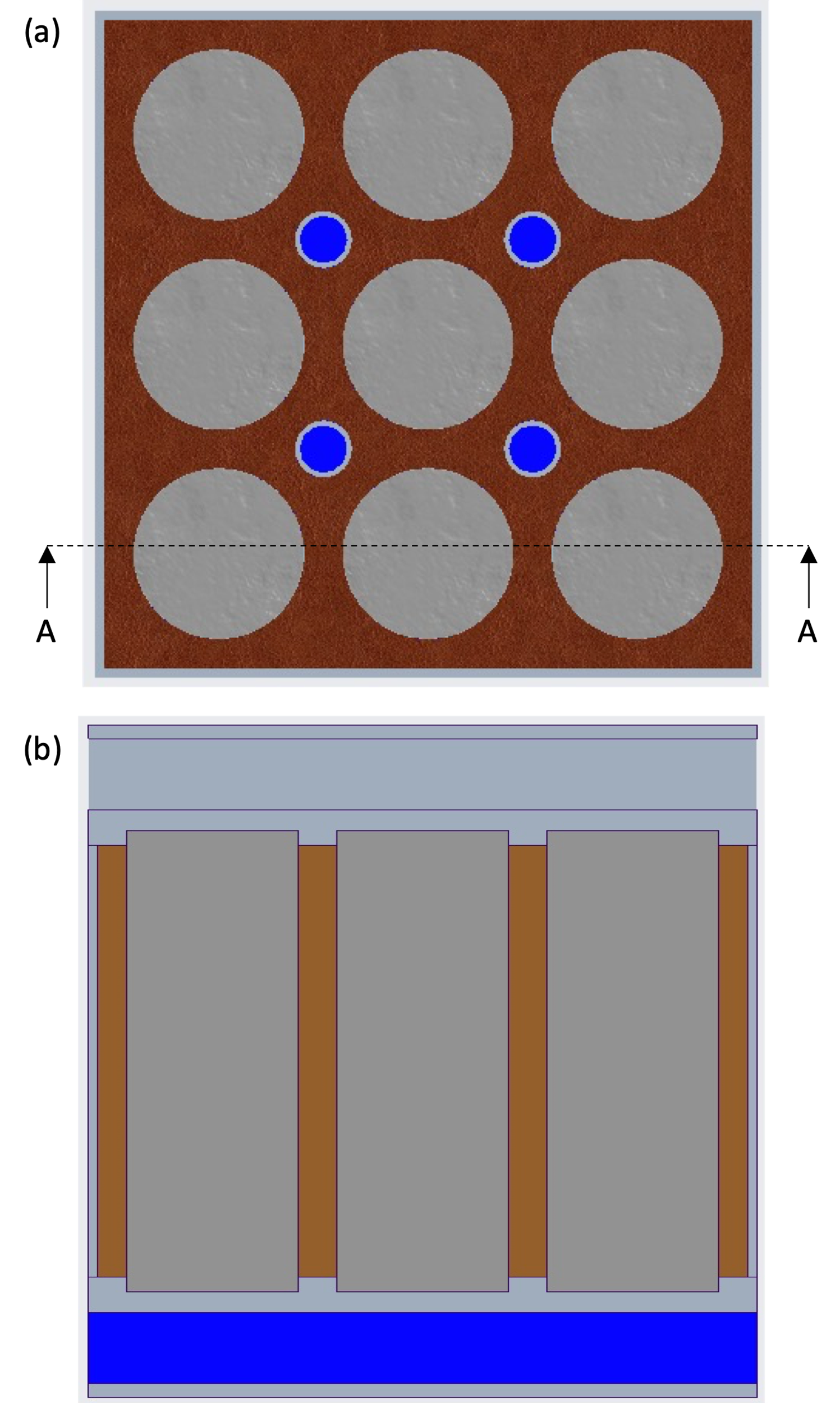
Table 1: Material properties of cooling mediums utilized in hybrid TMS.
|
Material Properties |
Air |
Water |
PCM 1 |
PCM 2 |
Poly-Alpha-Olefin |
|
Density (kg/m3) |
1.225 |
998.2 |
880 |
880 |
800 |
|
Specific Heat (J/kg.K) |
1,006 |
4,182 |
2,150 |
2,150 |
2,241 |
|
Thermal Conductivity (W/m.K) |
0.0242 |
0.6 |
0.21 |
0.21 |
0.14 |
|
Solidus Temperature (K) |
58 |
273 |
303 |
315 |
204 |
|
Liquidus Temperature (K) |
61 |
273 |
305 |
317 |
204 |
Three different concepts were developed for this study to compare the PCM and liquid cooling mediums. In the first concept (C1) and second concept (C2), the primary cooling medium was PCM 1 and PCM 2, respectively. Whereas in the third concept (C3), the primary cooling medium was Poly-Alpha-Olefin (PAO), which is an electrically insulating fluid. Since the primary cooling medium is in direct contact with the surface of the cells, therefore, an electrically insulating fluid was required. Additionally, PAO has a low density and high thermal conductivity and specific heat compared to other electrically insulating fluids available in the market [11]. Moreover, in all concepts, the secondary cooling mediums were water and air.
2.2. Numerical Modelling
Numerical modelling was conducted using ANSYS Fluent for the proposed concepts. For C1 and C2, the modelling was conducted by coupling the solidification/melting (PCM), energy, and flow models. For C3, on the other hand, the energy and flow models only were coupled. In all concepts, turbulence modelling was not included as the flow within the air duct was considered laminar. The governing equations are shown below [12].
Energy Equation:

where;
t Is time (s)
ρ is density (kg m-3)
E is energy (J)
 is velocity (m s-1)
P is pressure (Pa)
kT is effective thermal conductivity (W m-1 K-1)
T is temperature (K)
hj is specific enthalpy of species in specified phase (J/g)
Sh represents the volumetric heat sources.

Continuity Equation:
Sm represents any user defined sources.
Momentum Conservation Equation:
where;
 gravitational acceleration (9.81 m s-2)
 external body forces (N).
Energy equation for PCM (solidification/melting) model:

where;
H is the enthalpy (J)
S is the source term.
The mesh was developed using the ANSYS Meshing software. A combination of unstructured tetrahedral and hexahedral mesh was developed. Hexahedral mesh was used for the cell region and tetrahedral mesh was used for all the other battery pack regions. Inflation layers were created near the walls of the air duct only to capture the boundary layer of the airflow. Based on the mesh independence study, the chosen mesh consisted of 614,024 elements. Additionally, transient simulations were conducted to account for the phase change, and based on the time independence study, a time step size of 0.5 s was selected.
For all concepts, the ambient condition was set to 20 °C at atmospheric pressure. The inlet velocity of airflow with the air duct was set to 1.65 m/s based on the Reynolds number of 1950. The transient heat generation profile of the Li-ion 18650 cell was obtained at a 2 C discharge rate through the experimental study conducted in the author’s previous research [1]. The heat generation equation applied as a boundary condition at the surface of the cell was obtained by curve-fitting of the experimental profile and is shown below.

3. Results and Discussion
3.1. Numerical Model Validation
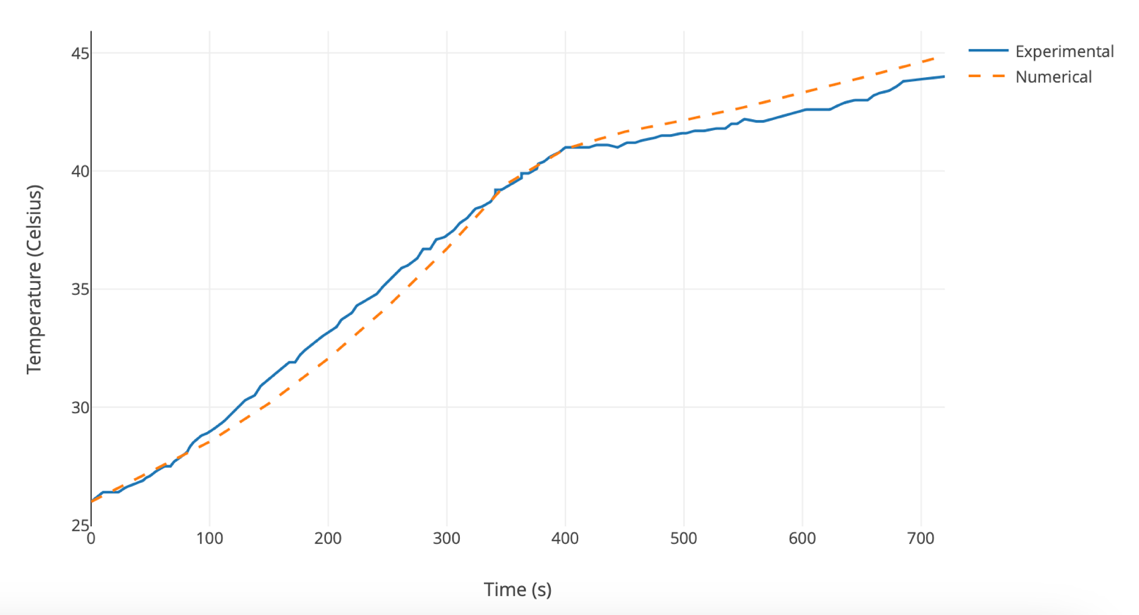
The numerical model developed was compared and validated with the experimental results provided in the open literature by Jiang et al. [13]. The experimental conditions and setup were replicated to validate the numerical model. The results of the validation study are shown in Figure 2. The variation between the numerical and experimental results was within 1 °C, which agrees with the validation requirements in the open literature [13]. Therefore, the results of the numerical model agree with the experimental results, and the model is considered validated.
3.2. Thermal Analysis
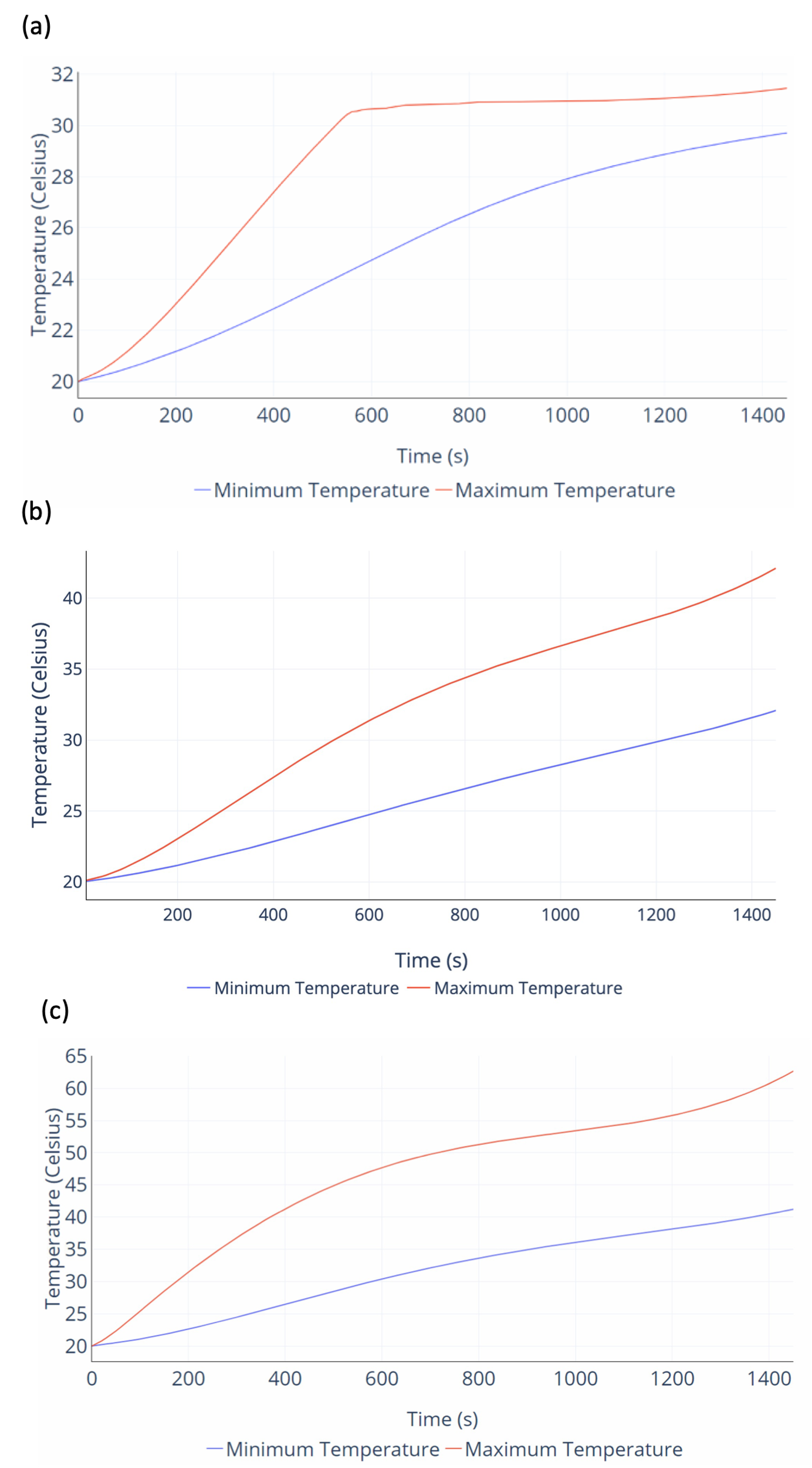
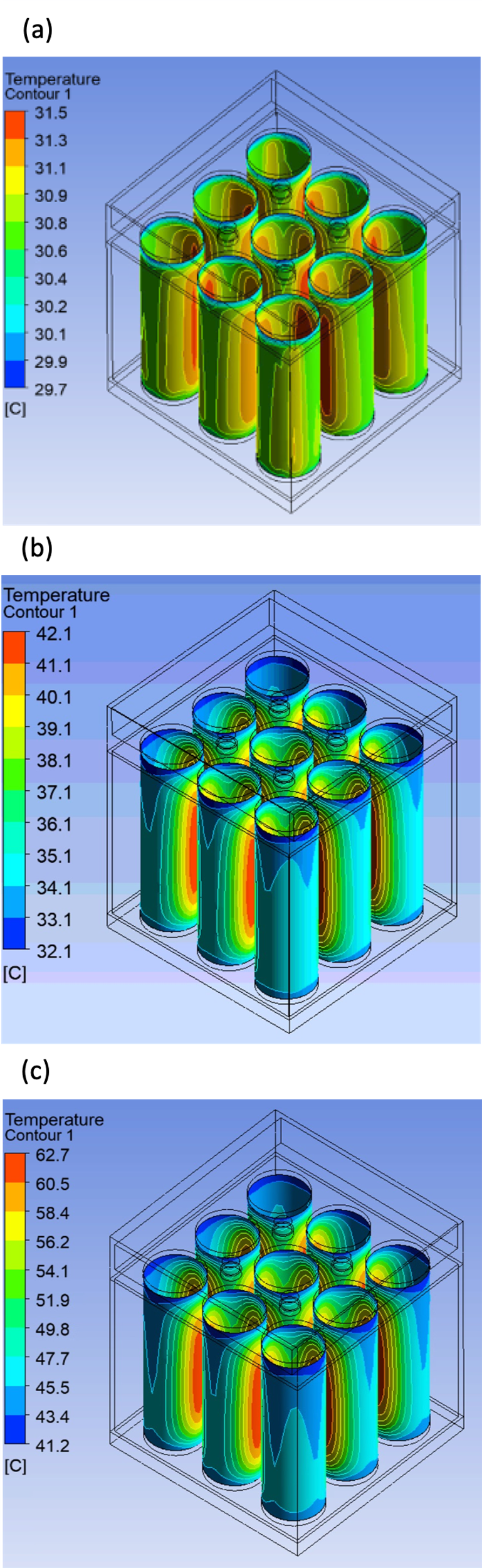
Li-ion cells require a specific thermal environment to perform effectively. The difference between the maximum temperature and the minimum temperature (temperature uniformity) should be maintained below 5 °C, and the maximum temperature of the cell should be maintained below 40 °C. The transient temperature profiles for C1, C2, and C3 are shown in Figure 3, and the temperature contours at the end of the discharge cycle are shown in Figure 4. For concept C1 (Figure 3a) the maximum temperature rises to the phase change temperature of the PCM until approximately 500 s. Beyond this, the maximum temperature of the cell stays within the phase change temperature range. Once the phase change of the PCM begins, then all the additional heat generation of the cell is used as latent heat for the PCM. The maximum temperature would start to increase once all the PCM is converted to liquid. However, in this scenario, the heat from the PCM is also extracted by the water in the liquid channels and is expelled into the environment through the natural evaporation process. Therefore, the total amount of liquid that was converted from solid was 6.13 %. Moreover, the minimum temperature of the cell stays below the phase change temperature range, hence, it does not reach a plateau and keeps on increasing until the discharge cycle of the cells. Similarly, in concept C2 (Figure 3b) both the maximum and the minimum temperatures do not reach the phase change temperature of PCM 2 during the discharge cycle, therefore, the gap between the maximum and minimum temperature keeps increasing. This results in a reduced temperature uniformity throughout the discharge cycle. Towards the end of discharge there is a temperature non-uniformity of 10 °C. Additionally, since the phase change temperature of PCM 2 is greater than PCM 1, the maximum temperature keeps increasing and it goes beyond 40 °C towards the end of the discharge cycle.
For concept C3 (Figure 3c), the maximum temperature increases throughout the discharge cycle and follows the heat generation rate of the cell. As the rate of heat generation reduces between 600 s and 1200 s, the rate of temperature increase also reduces and then increases, corresponding to an increase in the rate of heat generation. Since there is no continuous flow of fluid within the battery pack, the maximum temperature of the fluid also increases, and the secondary cooling medium air airflow on top of the battery pack is not sufficient to provide enough cooling to keep the temperatures within the desired ranges. The maximum temperature goes beyond 60 °C, and the minimum temperature increases to more than 40 °C.
It can be seen from Figure 4 that in all the concepts the temperature of the surface of the cell that faces the neighbouring cells is higher and the surface facing the battery pack housing is lower. Moreover, the lowest temperature is experienced by the part of the cell that in contact with the top plate and bottom plate of the housing. This is due to higher heat transfer through conduction between the cell and the top and bottom plates. Additionally, the airflow extracts some heat from the surface of the top plate which allows additional heat transfer from the cell surface, and it results in reduced temperatures at the top surface of the cell.
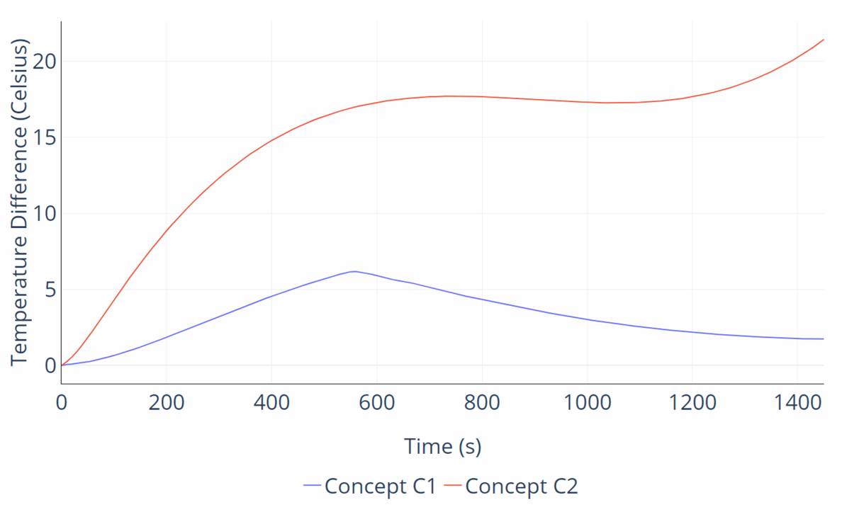
The difference between the maximum and minimum temperatures is shown in Figure 5. It can be seen that in concept C3 the temperature difference goes beyond 20 °C, which is not favourable for the operation of the Li-ion cells. Whereas, in concept C1, the temperature difference increases initially until phase change temperature is reached, and then it starts to reduce. Beyond ~500 s, the maximum temperature is maintained within a constant phase change temperature range, and the minimum temperature keeps increasing, which reduces the temperature difference and increases the temperature uniformity.
4. Conclusions
In this study, the problem of Lithium-ion cell cooling and temperature uniformity is addressed. A hybrid cooling strategy is designed by combining air, liquid, and phase change material mediums. The cells within the battery pack are surrounded by the primary cooling medium. There are liquid channels that run through the primary cooling medium to extract heat from them using the secondary cooling medium placed within the liquid channels. An air duct is added to the top of the battery pack to remove the evaporated secondary cooling medium into the environment and provide passive cooling within the hybrid strategy. Three different concepts are developed and compared. In the first and second concepts, the primary cooling medium used is a phase change material, and in the third concept, it is an electrically insulated fluid. The numerical model is validated from experimental results in the open literature. According to the results, the maximum temperature was maintained at approximately 31.5 °C by using the first concept, and the temperature uniformity was maintained at 1.75 °C. Therefore, the thermal performance requirement of maintaining the maximum temperature below 40 °C and temperature uniformity within 5 °C was achieved with minimal fluid pumping requirements as the fluid within the liquid channel is kept stationary.
References
[1] S. Shahid and M. Agelin-Chaab, "Analysis of cooling effectiveness and temperature uniformity in a battery pack for cylindrical batteries," Energies (Basel), vol. 10, no. 8, 2017, doi: 10.3390/en10081157. View Article
[2] Y. Wei and M. Agelin-Chaab, "Development and experimental analysis of a hybrid cooling concept for electric vehicle battery packs," J Energy Storage, vol. 25, no. August, p. 100906, 2019, doi: 10.1016/j.est.2019.100906. View Article
[3] S. Shahid and M. Agelin-Chaab, "A review of thermal runaway prevention and mitigation strategies for lithium-ion batteries," Energy Conversion and Management: X, vol. 16, p. 100310, Dec. 2022, doi: 10.1016/J.ECMX.2022.100310. View Article
[4] R. Mahamud and C. Park, "Reciprocating air flow for Li-ion battery thermal management to improve temperature uniformity," J Power Sources, vol. 196, no. 13, pp. 5685-5696, 2011, doi: 10.1016/j.jpowsour.2011.02.076. View Article
[5] S. Shahid, B. Chea, and M. Agelin-Chaab, "Development of a hybrid cooling concept for cylindrical li-ion cells," J Energy Storage, vol. 50, p. 104214, Jun. 2022, doi: 10.1016/J.EST.2022.104214. View Article
[6] S. Panchal, R. Khasow, I. Dincer, M. Agelin-Chaab, R. Fraser, and M. Fowler, "Thermal design and simulation of mini-channel cold plate for water cooled large sized prismatic lithium-ion battery," Appl Therm Eng, vol. 122, pp. 80-90, 2017, doi: 10.1016/j.applthermaleng.2017.05.010. View Article
[7] N. Javani, I. Dincer, and G. F. Naterer, "Numerical Modeling of Submodule Heat Transfer With Phase Change Material for Thermal Management of Electric Vehicle Battery Packs," J Therm Sci Eng Appl, vol. 7, no. 3, Sep. 2015, doi: 10.1115/1.4029053. View Article
[8] S. Shahid and M. Agelin-Chaab, "Development of hybrid thermal management techniques for battery packs," Appl Therm Eng, vol. 186, no. September 2020, p. 116542, 2021, doi: 10.1016/j.applthermaleng.2020.116542. View Article
[9] L. H. Saw, H. M. Poon, H. S. Thiam, Z. Cai, W. T. Chong, N. A. Pambudi and Y. J. King, "Novel thermal management system using mist cooling for lithium-ion battery packs," Appl Energy, vol. 223, no. April, pp. 146-158, 2018, doi: 10.1016/j.apenergy.2018.04.042. View Article
[10] S. Shahid and M. Agelin-Chaab, "Application of jets and vortex generators to improve air- cooling and temperature uniformity in a simple battery pack," J Therm Sci Eng Appl, vol. 11, no. 2, pp. 1-16, 2019, doi: 10.1115/1.4041493. View Article
[11] C. Roe, X. Feng, G. White, R. Li, H. Wang, X. Rui, C. Li, F. Zhang, V. Null, M. Parkes, Y. Patel, Y Wang, H. Wang, M. Ouyang, G. Offer, and B. Wu, "Immersion cooling for lithium-ion batteries - A review," Journal of Power Sources, vol. 525. Elsevier B.V., Mar. 30, 2022. doi: 10.1016/j.jpowsour.2022.231094. View Article
[12] ANSYS, ANSYS Fluent Theory Guide. 2020.
[13] G. Jiang, J. Huang, Y. Fu, M. Cao, and M. Liu, "Thermal optimization of composite phase change material/expanded graphite for Li-ion battery thermal management," Appl Therm Eng, vol. 108, pp. 1119-1125, Sep. 2016, doi: 10.1016/J.APPLTHERMALENG.2016.07.197. View Article