Journal of Fluid Flow, Heat and Mass Transfer (JFFHMT)
ISSN: 2368-6111

Volume 10 - Year 2023 - Pages 24-35
DOI: 10.11159/jffhmt.2023.004
Impact of Particle Size on the Selection of a Representative Bed Section for Poly-Dispersed Fixed Bed Reactors
Stylianos Kyrimis1,2, Robert Raja2, Lindsay-Marie Armstrong1
1School of Engineering, University of Southampton, UK, SO17 1BJ
2School of Chemistry, University of Southampton, UK, SO17 1 BJ
stylianos.kyrimis@soton.ac.uk, l.armstrong@soton.ac.uk
Abstract - Computational Fluid Dynamics (CFD) models are a valuable tool for the design, optimization, and scaling-up of fixed bed chemical reactors. However, the realistic representation of the catalytic bed structure and the mesh quality of the 3D geometry is of paramount importance to improve the accuracy of CFD models. For the former, computed tomography (CT) is a non-destructive method to map and generate the internal structure of experimental fixed bed reactors, enabling a direct 1-to-1 coupling between experiments and simulations. In our previous work, the internal structure of highly poly-dispersed fixed bed reactors, formed by sieved particles, was analysed. The particles that formed them displayed a wide range of sizes, shapes, and orientations. Due to the local topological complexity of these beds, meshing and simulating their entire volume would lead to exhaustive computational demands. To reduce these, a suitable sample section should be selected, which accurately represents both the bulk and the radial porosity of the full bed. Three distinct sample sections were quantified here for their accuracy, identifying that, due to the highly heterogeneous nature of the full beds, sample selection is case sensitive. In addition, compared to smaller particles, larger particles form more heterogeneous local structures, thus requiring longer sections to accurately represent the full bed. A selected 10% section was then meshed, and its hydrodynamic profile resolved, to evaluate its mesh independency. The results highlight the importance of choosing a suitable bed section and mesh size to reduce the computational demands, minimise the computational errors, and achieve the desired level of solution detail.
Keywords: Computational Fluid Dynamics (CFD), polydispersed beds, fixed bed chemical reactors, computed tomography (CT), catalytic particles, SAPO-34
© Copyright 2023 Authors - This is an Open Access article published under the Creative Commons Attribution License terms Creative Commons Attribution License terms. Unrestricted use, distribution, and reproduction in any medium are permitted, provided the original work is properly cited.
Date Received: 2023-06-03
Date Revised: 2023-07-08
Date Accepted: 2023-07-20
Date Published: 2023-08-08
1. Introduction
The strict greenhouse gas emission reduction targets set by the International Energy Agency (IEA) aim for net zero emissions by 2050 [1-3]. Achieving this requires the modernisation of all energy sectors. Among these, modernisation of the transportation sector is especially critical. In 2022, the transportation sector accounted for 7.98 Gt of CO2 emissions [2], with the International Maritime Organisation (IMO) predicting further emissions growth by 2050 [4]. While electrification has been suggested as a potential solution, this strategy is not suitable for heavy-duty road transport, aviation, or maritime transport [4]. Consequently, alternative strategies are required, such as the replacement of the currently used fossil fuels with next-generation carbon-neutral fuels, which are directly integrable into the existing infrastructure, such as methanol and dimethyl ether [4, 5]. The sustainable bulk production of these carbon-neutral fuels can have a profound impact in all aspects of a future sustainable society.
Methanol, dimethyl ether, and other key chemicals such as sulfuric acid and ammonia, are predominantly produced by fixed bed chemical reactors [6-8]. Optimising these reactors can be key for the timely transition to a carbon-neutral society. For this, Computational Fluid Dynamics (CFD) models can play a valuable role, acting as detailed investigative and optimisation tools [9-11]. Prior to their utilisation, however, CFD model development is critical, especially focused on the methodology used to depict the fixed bed morphology. The morphology of the fixed bed affects all aspects of heat and mass transfer within the reactor, and thus its chemical performance [12]. Consequently, for CFD models to produce valuable results, the reproduced 3D bed structure should match as close as possible the structure of the actual experimental reactor. One of the primary methods to synthetically generate a realistic 3D bed structure is the Discrete Element Method (DEM), which places particles of arbitrary shapes into a cylindrical container [12, 13].
Using DEM-generated beds, formed by mono-dispersed spherical particles, the interconnection between the bed structure and its hydrodynamic profile has been widely investigated [14-17]. By utilising a mono-dispersed packed bed of spheres, Tobiś investigated both experimentally and computationally the turbulent flow of air [18, 19], identifying the considerable impact of the local bed structure on the flow velocity and pressure drop. Bai et al. investigated both experimentally and computationally the pressure drop within packed beds of both spheres and cylinders [20]. Both a laboratory-scale reactor (153 particles) and a plant-scale reactor (up to 1545 particles) were generated by DEM and simulated with CFD [20]. To reduce the computational resources, a small section of the plant-scale reactor was chosen. They identified that for the bed section to be an accurate representation, its porosity should be as close as possible to that of the full bed. Otherwise, even a 10% porosity deviation between the physical and the generated bed could lead to a 30% deviation in the pressure drop predictions [20]. Recent DEM-CFD studies consider more complex particle form aspects, such as shape and orientation, with particles being modelled as cylinders, Raschig rings, and trilobes, to name a few [21-24]. By comparing cylindrical and Flatted ring particles, Tabib et al. identified that particle shape and orientation plays a key role in the heat and mass transfer characteristics of the fixed bed [25]. Karthik and Buwa identified that particle shape changed the pressure drop, the temperature profile, and the chemical performance of the bed [26]. Moreover, they identified the optimal particle shape for each of the methane steam reforming, the water-gas shift, the methanol synthesis, and the dimethyl ether synthesis reactions [26].
Poly-dispersity is a term that refers to both the shape and the size of the particles forming the bed being non-homogeneous. Due to their complexity, and with the particle size, shape, and orientation all affecting the behaviour of fixed bed reactors, a fundamental understanding of poly-dispersed fixed bed reactors has not been reached [27]. This drives the need for more complex CFD investigations.
Zhang et al. investigated poly-dispersed beds formed by cylindrical particles, with the particle size following a Gaussian distribution [28]. Poly-dispersity resulted in a less loosely packed bed compared to mono-dispersed beds [28]. The radial porosity profiles followed similar trends for the mono- and the poly-dispersed beds close to the reactor wall, however, the two profiles deviated close to the bed centre. The poly-dispersed bed was then utilised for CFD simulations, allowing the authors to observe that flow profiles within the interparticle pores were highly heterogeneous [28]. Boccardo et al. synthetically generated beds of spheres, cylinders, and trilobes and compared their accuracy, in terms of their bed structure and flow profiles, with experimental data [29]. Particle size heterogeneity was also introduced. The geometries were utilised for CFD simulations, with the results being compared to theoretical correlations, showcasing their accuracy [29]. Special focus was put into identifying a suitable section of the full bed to reduce the mesh sizes and the computational demands of the complex bed structures. They identified that a suitable bed section should respect both the bulk porosity and the near-wall radial porosity profile of the full bed [29].
Aside from synthetically-generated beds, imaging methods offer a direct coupling between experimental setups and CFD models [30, 31]. Mantle et al. used 3D Magnetic Resonance Imaging (MRI) and MRI velocimetry to characterise the structure and flow field through a packed bed of alumina particles and compare the results with CFD simulations [32]. They observed that flow through the pores was highly heterogeneous, with 40% of fluid flowing through 10% of the pores [32]. Suzuki et al. used Computed Tomography (CT) to map the internal structure of mono-dispersed spherical beds [33]. The scans were then used to produce a theoretical correlation to predict radial porosity profiles, based on an amplitude and a damping factor [33].
All these studies reveal that accurate coupling and representation of the experimental bed structure with CFD models is of utmost importance when it comes to solution accuracy. In our previous work, we used CT to reproduce and analyse the 3D bed structure of three poly-dispersed laboratory-scale catalytic beds [34]. These beds were formed by SAPO-34 particles, whose size was controlled by passing them through sieves of 100-300, 300-500, and 500-700 μm in size [34]. The limited control offered by laboratory techniques resulted in the loaded particles displaying a wide range of sizes and forms. The produced CT images were then used to evaluate the poly-dispersed bed structure in terms of bulk, radial, and axial porosities [34]. By comparing their porosity profiles with those produced by mono-dispersed spherical beds, significant differences were observed [34]. Producing CFD simulations for these CT-scanned geometries will yield unique observations, as this level of poly-dispersity cannot be easily achieved with DEM-generated beds. Due to their highly complex topological nature, however, the computational demands associated with meshing these geometries could quickly become prohibitive. Keeping these demands at reasonable levels necessitates either cleaning the produced CT images or using smaller bed sections. Because of the fragile nature of the SAPO-34 particles, fractures were created during the loading process, thus dust particles (<100 µm) were generated. To generate smaller and smoother computational meshes, these particles need to be removed, a process achieved through image-processing operations. In our follow-up study, the local topological differences introduced by different image-processing methodologies were investigated [35]. It was identified that cruder image-processing methods introduced small deformations in the porosity and interparticle network characteristics, which then considerably changed the hydrodynamic behaviour of the bed [35]. Here, we investigate the accuracy of representing the full catalytic bed using only a small sample section, as well as the best meshing setup to achieve mesh independency while reducing the computational demands.
2. Methodology
Work in this paper focuses primarily on the 100-300, 300-500, and 500-700 μm cases of our previous work [34], whose particles were passed five times through the respective sieve fractions. This is because increasing the number of sieve passes offered more control over the particle sizes and forms, thus the produced beds were more homogeneous [34].
2.1. Representative bed section
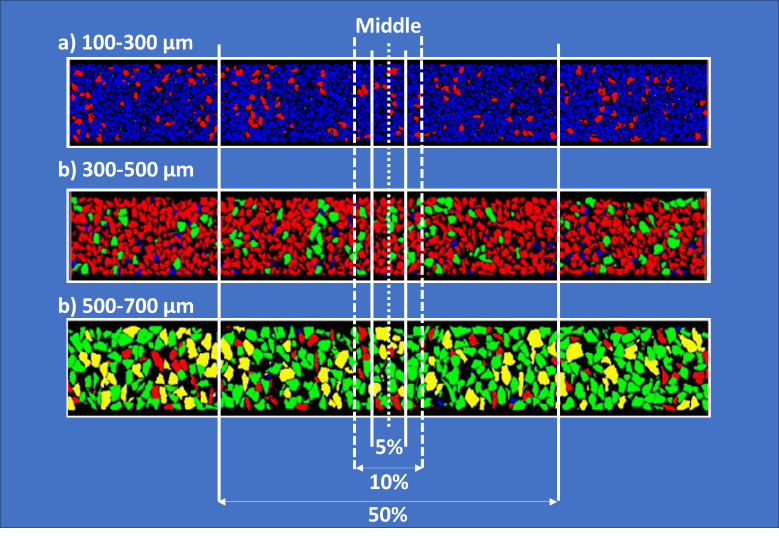
As highlighted by both Bai et al. [20] and Boccardo et al. [29], selecting a suitable section of the entire catalytic bed can be a reasonable approach to reduce the computational demands of particle-resolved models. However, for this sample section to be an accurate representation, both its bulk and its radial porosity should match those of the full bed as close as possible. To identify this, three sample sections were chosen, corresponding to 5%, 10%, and 50% of the full 100-300, 300-500, and 500-700 μm beds. These sections span upwards and downwards from the centre of the full bed, as can be seen in Figure 1. Particle colours represent their equivalent diameter metric, as defined in our full bed analysis [34], with blue: 100-300 μm, red: 300-500 μm, green: 500-700 μm, and yellow: >700 μm. Similarly to the full bed, the sections of both geometries consist of a range of particle sizes and shapes.
2.2. Porosity estimation
The method used to estimate the bulk and radial porosities of the full bed was described in detail in our previous work and is repeated here. The binary CT images were fragmentised into concentric rings with a thickness of 0.05 mm, thus creating a radial region along the full bed length. In this area, the “Analyze Particles” function from Fiji ImageJ [36, 37] software was used to quantify the area covered by the particles and compare it to the total area of the concentric rings. By integrating this area over the entire bed section, the total area covered by the particles, and thus the packing density, can be quantified.
Table 1: Computational resources of the 10% section of the 300-500 μm bed. Simulations were performed with 2 Intel Xeon 6130 2.1 GHz CPUs with 158 Gb of allocated RAM.
|
Coarse |
Medium |
Refined |
|
|
Mesh elements |
11.0 M |
18.8 M |
22.3 M |
|
File size [Gb] |
1.04 |
1.8 |
2.1 |
|
Computational time per 100 iterations [sec] |
108 |
361 |
371 |
|
Ram utilisation [Gb] |
35.3 |
68.9 |
68.7 |
2.3. Image-processing
The generated CT images contained a significant population of dust particles, i.e., particles smaller than 100 μm. These particles, while numerous, occupy a negligible volume of the full bed [34]. As the focus of our previous study was the accurate characterisation of the bed structure, these particles were maintained. Furthermore, the qualification of the most suitable sample section and the porosity estimation for all 3 cases was performed on the unprocessed images, using the same methodology as that used to determine the structure of the original full beds [34]. However, to mesh and simulate the flow field, retaining such particles would quickly lead to large meshes and exhaustive computational demands, as high local refinement would be necessary to avoid heavily skewed computational cells. Meshing quality and independency are both key for accurate CFD results [29, 38]. Consequently, to preserve the mesh quality and reduce its overall size, dust-like particles should be removed. This is possible by processing the produced CT images using the Fiji ImageJ software [37]. The image-processing methodology used here followed the operations that produced the smallest mesh sizes, as determined by our previous work [35]. Specifically, the Erode, Dilate, and Close operations were sequentially applied. Erode removes pixels from the edges of binary images, Dilate adds pixels, and Close sequentially performed a Dilate and Erode operation [39].
2.4. Geometry meshing
Following image-processing, meshing operations were performed. For this work, meshing was focused solely on the 10% section of the 300-500 μm bed, aiming to identify the mesh size where mesh independency is achieved. Only the interparticle pore space is meshed, while the catalytic particles are neglected, i.e., treated as void, unmeshed regions. In addition, empty fluid regions were added prior and after the catalytic bed, with a length of 0.6 and 1.8 mm respectively, to allow a stable flow during the CFD simulations.
Following image-processing, meshing was performed with the Simpleware ScanIP software from Synopsys Inc. Further processing was done in Simpleware, using “Island Removal”, to remove any unconnected particles smaller than 60 μm that were retained after the image-processing operations. Meshing was performed with the +FE Free algorithm. This algorithm uses adaptive tetrahedral elements to preserve the small features and the complex topological structure within the porous region [40]. To identify mesh independency, three refinement levels are considered by controlling the coarseness of the +FE Free algorithm, with the characteristics of the produced meshes being presented in Table 1.
2.5. Solution setup
The hydrodynamics of the 10% 300-500 μm bed section were resolved using the 3D double precision ANSYS Fluent v22.2 solver. Fluent solves the mass and momentum conservation equations of the fluid in their steady-state, laminar form [41], as presented in eqn. (1) and (2), respectively.
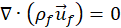
Here, ![]() and ρf are the fluid velocity and density, respectively, P is the pressure drop,
and ρf are the fluid velocity and density, respectively, P is the pressure drop, ![]() is the stress tensor, and
is the stress tensor, and ![]() is the gravitational acceleration. Air flow at atmospheric pressure and ambient temperature was considered, while the direction of the gravitational acceleration was defined to follow the flow path, i.e., from inlet to outlet. The SIMPLE algorithm was used for pressure-velocity coupling, with a Second Order upwind scheme. Under-relaxation factors of 0.5 were used for pressure and momentum, while residual targets were set to 1e-4. Solution proceeded until convergence was reached. All cases were simulated on the IRIDIS 5 high performance computing facility, utilising 2 Intel Xeon 6130 2.1 GHz CPU, with 158 Gb of allocated RAM. The computational resources, estimated as computational time necessary for 100 iterations to be resolved, and as RAM utilisation, are also presented in Table 1.
is the gravitational acceleration. Air flow at atmospheric pressure and ambient temperature was considered, while the direction of the gravitational acceleration was defined to follow the flow path, i.e., from inlet to outlet. The SIMPLE algorithm was used for pressure-velocity coupling, with a Second Order upwind scheme. Under-relaxation factors of 0.5 were used for pressure and momentum, while residual targets were set to 1e-4. Solution proceeded until convergence was reached. All cases were simulated on the IRIDIS 5 high performance computing facility, utilising 2 Intel Xeon 6130 2.1 GHz CPU, with 158 Gb of allocated RAM. The computational resources, estimated as computational time necessary for 100 iterations to be resolved, and as RAM utilisation, are also presented in Table 1.
3. Results
3.1. Porosity profiles
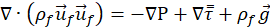
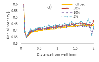
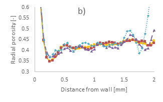
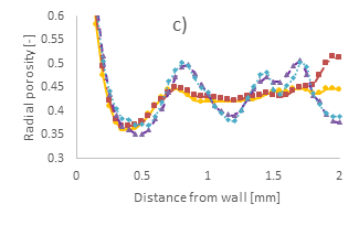
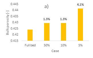
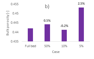
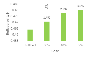
The radial porosity profiles of the different bed sections of the 100-300, 300-500, and 500-700 μm cases are presented in Figure 2. a, b, and c, respectively. In addition, the bulk porosity magnitude of the different cases is presented in Figure 3. As a reference, respective data for the full bed cases are also presented, as per [34].
For the 100-300 µm case, the 50% section accurately reproduces the radial porosity profile of the full bed section, Figure 2a, albeit its overall magnitude is larger. This is also depicted in its bulk porosity, Figure 3a, which is 1.3% higher in magnitude compared to the full bed. The 10% section achieves a similar magnitude difference in its bulk porosity, equal to 1.3% as per Figure 3a, but its radial porosity, Figure 2a, presents more intense oscillations compared to the profile of the full bed. Noticeably, the radial profile of the 10% section near the bed centre presents a local minimum. On the contrary, the 5% section presents both large oscillations and considerable differences in its bulk porosity magnitude, 4.1%, compared to the full bed.
Similar conclusions can be observed in the 300-500 μm case. Specifically, the 50% section accurately reproduces the first and second radial porosity oscillations near the container wall; however, deeper into the bed, its oscillations present larger amplitudes compared to the full bed’s profile. Furthermore, its bulk porosity is very close to that of the full bed, with a deviation of 0.5%. On the contrary, as was also observed in the 100-300 µm case, the 5% section presents very large oscillations along the entire radial length. Especially in the near-centre region, there is a significant resurgence of oscillations, reaching a porosity of almost 0.77 in the bed centre. This confirms the observations from our previous work [34], that, when the bed is broken down into smaller sections, its structure is highly heterogeneous, while when a global radial porosity is derived, its profile appears smooth.
Due to this largely empty region in the bed centre of both 100-300 and 300-500 µm cases, channelling flow could take place. This is the same phenomenon observed in near-wall regions for fixed bed reactors, where the flow moves through the pores uninterrupted [16, 42]. Consequently, the overall reactivity and chemical performance of the bed is hindered as reactants in those regions do not come into contact with the catalytic material. For spherical beds, such empty channels in the centreline of the bed are only observed for small container-to-particle diameter ratios, i.e., N ≤ 2.6 [13]. The 100-300 and 300-500 μm cases, however, have an average N-ratio of around 20 and 10, respectively, thus such topological structures are not expected. The 5% section confirms that large heterogeneities in particle sizes, shapes, and orientations, can locally generate large gaps, resulting in flow profiles that would be significantly different than those of mono-dispersed spherical beds. The bulk porosity of the 5% section also deviates significantly from the full bed case. The 10% section has a radial profile in-between the 5% and 50% sections, also showcasing resurgence of oscillations in the near-centre region. However, the overall trend of the full bed case is well captured, while its bulk porosity is the closest to the full bed case, with an error of 0.2%.
On the contrary, for the 500-700 μm case, both the 5% and the 10% sections have very similar radial profiles, producing oscillations with considerably larger amplitudes and periods compared to the full bed case. The 50% section produces a radial profile which is very close to that of the full bed along most of the radial length but showcases a resurgence in oscillations near the bed centre. The bulk porosity follows an inverse trend with the bed section, with the smallest error, equal to 1.4%, being produced by the 50% section and the biggest error, equal to 3.5%, being produced by the 5% section.
These results are indicative of the relationship between bed structure heterogeneity and particle size. As the size of the particles is increased, and with them being deposited at various random orientations, bigger local interparticle pores are created, as also seen in our interparticle network analysis [35]. Consequently, bulk porosity is then increased from 42% (100-300 µm), to 44% (300-500 μm), and to 46% (500-700 μm). The increase of empty pores is also evident by examining the black regions of Figure 1a-c.
Conclusively, smaller sections are associated with larger errors and deviations from the full bed, as local heterogeneities are more pronounced. However, the smaller the particle size of the considered case, the smaller the bed section necessary to derive a representative volume. As a result, because of the highly heterogeneous nature of such beds, selection of the most suitable sample section is case dependent. For the 100-300 and 300-500 μm cases, while the 10% section does not reproduce the radial profiles as accurately as the 50% section, it gives a satisfactory representation of the full bed. As a result, and with the goal of reducing the computational mesh size, the 10% section is suitable to study the flow profiles of these cases. For the 500-700 μm case, however, the 10% section produces very large oscillations, while the error in the bulk porosity is rather large, equal to 2.9%. As a result, the 50% section would be a more suitable candidate. In this work, meshing and CFD simulations are performed solely for the 300-500 μm case.
3.1. Mesh independency
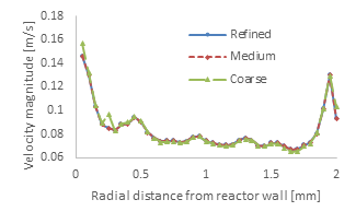
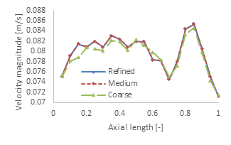
Mesh independency is evaluated by examining the radial and axial profiles of the velocity magnitude and pressure profiles. Figure 4a compares the average velocity magnitude of the different meshes at the concentric rings used to estimate the bed’s radial porosity of Figure 2, integrated over the entire radial length of the bed. Figure 4b compares the average velocity magnitude of the different meshes integrated over various axial lengths, each with an axial thickness of 0.05% of the total bed section length.
The differences in the velocity magnitude profiles clearly indicate the solution accuracy achieved as the mesh is further refined. Mesh independency has been achieved at the medium refinement level, as both its radial and axial velocity magnitude profiles are very close to those of the refined mesh. For the coarse mesh, while both the radial and axial velocity profile trends are accurately reproduced, there are some deviations from the profiles of the other two cases. Specifically, for the radial profiles, Figure 4a, the local region at a radial distance of around 0.25 mm from the wall (i.e., around half a particle diameter) is not accurately resolved with the coarse mesh. Similarly, along the axial profiles, Figure 4b, both the medium and the refined cases predict sharp velocity peaks which are not always reproduced by the coarse mesh. The topological features of the CT geometries are highly complex [34, 35], containing narrow interparticle gaps which are formed in-between neighbouring particles. Such topological features cannot be accurately discretised by the coarse mesh, thus errors in the local flow profiles are introduced. As a result, the average error between the coarse and the refined mesh cases is around 1.6% and 1.0% for the radial and axial velocity profiles, respectively.
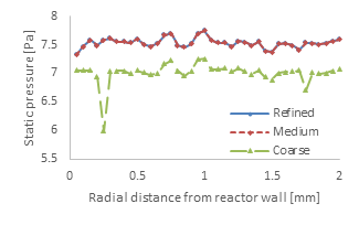
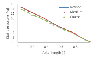
The radial and axial pressure profiles for the three cases are presented in Figure 5a and b, respectively. Similarly to the velocity profiles, the pressure profiles between the medium and the refined meshes are very close, further supporting that mesh independency has been reached. While capturing the overall trend, the coarse mesh predicts a lower pressure magnitude, both along the radial and the axial profiles. Specifically, compared to the refined mesh, the coarse mesh produced an average error of 6.9% and 6.2% for the radial and axial pressure profiles, respectively. The discrepancies in the velocity magnitude profiles around the radial distance of 0.25 mm from the wall are also noticeable here, expressed as a local pressure decrease, as per Figure 5a.
This study incorporates accurate experimental bed morphologies and porosity profiles, extracted from CT scans, to evaluate the hydrodynamic sensitivity in response to the experimental conditions. Further studies are currently underway for direct in situ validation of individual flow and chemical performance to evaluate the scale-up potential.
With the available data, it becomes evident that selection of both a suitable bed section and a suitable mesh refinement level are key for accurate CFD results. A 50% section, combined with a medium mesh refinement, would lead to the most accurate results for all three cases. Unfortunately, computational resources are a considerable limitation that should be considered. If the 50% section of the 300-500 μm bed was instead meshed, and a linear increase of the computational resources of Table 1 was assumed, then mesh size and file size would be increased to 55M/5.2 Gb and 94M/8.9 Gb for the coarse and medium refinement levels, respectively. With such an increase, case setup, computational solution, and result processing would be a challenging task even for cluster-level machines. In fact, a linear increase of the mesh with the bed section is a conservative scenario; due to its topological complexity, expecting an exponential increase would be far more realistic. Furthermore, the current geometry only resolves the interparticle pore space and solely considers the mass and momentum conservation equations. The size of the computational mesh would double with the inclusion of the catalytic particles in the 3D geometry. Moreover, solution of the energy and species conservation equations, which will provide an overview of the heat transfer and chemical reactions within the bed, would significantly increase the computational time and resulting file size. These considerations highlight that simplifications and assumptions are inevitable. Consequently, based on the considered study, computational engineers should balance the level of detail required, the computational resources available, and the maximum acceptable error, to reach a decision on the most suitable CFD setup.
Both velocity and pressure parameters showcase significant local changes in their magnitudes. Furthermore, as was observed in our previous study [35], flow through the pores is highly heterogeneous, with some particles residing in low-flow regions. Such flow profiles could lead to poor heat transfer and inefficient catalyst utilisation at some bed regions, thus inhibiting the performance of the reactor. Consequently, understanding the flow field within highly poly-dispersed beds will produce valuable observations for reactor engineering, aimed at efficiently utilising the catalyst and maximising the product yield.
4. Conclusions
Combining imaging methods which map the internal structure of catalytic fixed bed reactors, such as computed tomography (CT), with computational fluid dynamics (CFD) solvers, allows for a unique coupling between experimental setups and simulation models. Unlike synthetically-generated mono- or poly-dispersed beds, CT-scans are able to directly translate the experimental reactor into a 3D geometry, available for meshing and simulating. In our previous work, fixed bed reactors, consisting of 100-300, 300-500, and 500-700 μm SAPO-34 particles, were scanned through CT, and their internal morphological structure was analysed. Due to their poly-dispersed nature, particles of a wide range of sizes, shapes, and orientations were observed, creating complex topological arrangements.
Meshing and simulating these structures could quickly lead to exhaustive computational demands, thus necessitating the selection of smaller sample sections. For these sections to be suitable, however, they should match the structural morphology of the full bed. To quantify this, three sections were chosen, equal to 5%, 10%, and 50% of the full bed. It was observed that, due to the high irregularity of the bed structure, a suitable sample section is case-dependent. In addition, particle size affects the sample section selection, with larger particle sizes requiring longer sections. For the 100-300 and 300-500 μm cases, a section of 10% is suitable, as it is an acceptable representation of the full bed, in terms of radial and bulk porosities. Due to its highly irregular nature, however, for the 500-700 μm case, a 50% section of the total bed is better suited compared to a 10% section. The selected 10% section of the 300-500 μm case was then meshed, and a mesh independency study was performed by solving the mass and momentum conservation equations. Choosing a coarser mesh introduces an error of around 1.6% and 6.9% in the radial velocity and pressure profiles, respectively, as local topological structures are not accurately resolved, but its computational resources are greatly reduced compared to more refined meshes. These results highlighted the necessity to balance computational demands with solution accuracy.
Acknowledgements
The authors would like to thank the Industrial Decarbonisation Research and Innovation Centre (IDRIC), grant number (EP/V027050/1), for their funding. In addition, the authors would like to acknowledge the use of the IRIDIS 5 High Performance Computing Facility, and associated support services at the University of Southampton, in the completion of this work. This paper is an extension of the work presented and submitted on the proceedings of the 10th International Conference on Fluid Flow, Heat and Mass Transfer (FFHMT’23), with a DOI: 10.11159/ffhmt23.171.
References
[1] International Energy Agency (IEA), "Achieving Net Zero Heavy Industry Sectors in G7 members," Paris, 2022. [Online]. Available: https://www.iea.org/reports/achieving-net-zero-heavy-industry-sectors-in-g7-members
[2] International Energy Agency (IEA), "CO2 Emissions in 2022," Paris, 2023. [Online]. Available: https://www.iea.org/reports/co2-emissions-in-2022
[3] International Energy Agency (IEA), "Net Zero by 2050," Paris, 2021. [Online]. Available: https://www.iea.org/reports/net-zero-by-2050
[4] G. Hutchings et al., Sustainable synthetic carbon based fuels for transport, Policy Briefing. London: The Royal Society, 2019/9/20.
[5] The Solent Cluster. "Working together for a lower carbon future." https://www.thesolentcluster.com/ (accessed).
[6] G. Bozzano and F. Manenti, "Efficient methanol synthesis: Perspectives, technologies and optimization strategies," Progress in Energy and Combustion Science, vol. 56, pp. 71-105, 2016/09/01/ 2016, doi: https://doi.org/10.1016/j.pecs.2016.06.001. View Article
[7] M. Zhang and Y. Yu, "Dehydration of Ethanol to Ethylene," Industrial & Engineering Chemistry Research, vol. 52, no. 28, pp. 9505-9514, 2013/07/17 2013, doi: 10.1021/ie401157c. View Article
[8] Ronald W. Missen, Charles A. Mims, and B. A. Saville, Introduction to Chemical Reaction Engineering and Kinetics. Wiley, 1999.
[9] A. G. Dixon and B. Partopour, "Computational Fluid Dynamics for Fixed Bed Reactor Design," Annual Review of Chemical and Biomolecular Engineering, vol. 11, no. 1, pp. 109-130, 2020, doi: 10.1146/annurev-chembioeng-092319-075328. View Article
[10] B. Partopour and A. G. Dixon, "110th Anniversary: Commentary: CFD as a Modeling Tool for Fixed Bed Reactors," Industrial & Engineering Chemistry Research, vol. 58, no. 14, pp. 5733-5736, 2019/04/10 2019, doi: 10.1021/acs.iecr.8b06380. View Article
[11] S. Kyrimis, M. E. Potter, R. Raja, and L.-M. Armstrong, "Understanding catalytic CO2 and CO conversion into methanol using computational fluid dynamics," Faraday Discussions, 10.1039/D0FD00136H vol. 230, no. 0, pp. 100-123, 2021, doi: 10.1039/D0FD00136H. View Article
[12] A. G. Dixon, M. Nijemeisland, and E. H. Stitt, "Packed Tubular Reactor Modeling and Catalyst Design using Computational Fluid Dynamics," Computational Fluid Dynamics, vol. 31, pp. 307-389, 2006, doi: 10.1016/s0065-2377(06)31005-8. View Article
[13] J. Theuerkauf, P. Witt, and D. Schwesig, "Analysis of particle porosity distribution in fixed beds using the discrete element method," Powder Technology, vol. 165, no. 2, pp. 92-99, 2006/07/13/ 2006, doi: https://doi.org/10.1016/j.powtec.2006.03.022. View Article
[14] A. G. Dixon, "Local transport and reaction rates in a fixed bed reactor tube: Exothermic partial oxidation of ethylene," Chemical Engineering Science, vol. 231, p. 116305, 2021/02/15/ 2021, doi: https://doi.org/10.1016/j.ces.2020.116305. View Article
[15] B. Partopour and A. G. Dixon, "Integrated multiscale modeling of fixed bed reactors: Studying the reactor under dynamic reaction conditions," Chemical Engineering Journal, vol. 377, p. 119738, 2019/12/01/ 2019, doi: https://doi.org/10.1016/j.cej.2018.08.124. View Article
[16] T. Atmakidis and E. Y. Kenig, "CFD-based analysis of the wall effect on the pressure drop in packed beds with moderate tube/particle diameter ratios in the laminar flow regime," vol. 155, no. 1-2, pp. 404-410, 2009, doi: 10.1016/j.cej.2009.07.057. View Article
[17] S. Das, N. G. Deen, and J. A. M. Kuipers, "A DNS study of flow and heat transfer through slender fixed-bed reactors randomly packed with spherical particles," Chemical Engineering Science, vol. 160, pp. 1-19, 2017/03/16/ 2017, doi: https://doi.org/10.1016/j.ces.2016.11.008. View Article
[18] J. Tobiś, "Modeling of the Pressure Drop in the Packing of Complex Geometry," Industrial & Engineering Chemistry Research, vol. 41, no. 10, pp. 2552-2559, 2002/05/01 2002, doi: 10.1021/ie010541c. View Article
[19] J. Tobiś, "Influence of bed geometry on its frictional resistance under turbulent flow conditions," vol. 55, no. 22, pp. 5359-5366, 2000, doi: 10.1016/s0009-2509(00)00155-x. View Article
[20] H. Bai, J. Theuerkauf, P. A. Gillis, and P. M. Witt, "A Coupled DEM and CFD Simulation of Flow Field and Pressure Drop in Fixed Bed Reactor with Randomly Packed Catalyst Particles," Industrial & Engineering Chemistry Research, vol. 48, no. 8, pp. 4060-4074, 2009/04/15 2009, doi: 10.1021/ie801548h. View Article
[21] N. Jurtz, G. D. Wehinger, U. Srivastava, T. Henkel, and M. Kraume, "Validation of pressure drop prediction and bed generation of fixed-beds with complex particle shapes using discrete element method and computational fluid dynamics," AIChE Journal, vol. 66, no. 6, p. e16967, 2020/06/01 2020, doi: https://doi.org/10.1002/aic.16967. View Article
[22] G. D. Wehinger, C. Fütterer, and M. Kraume, "Contact Modifications for CFD Simulations of Fixed-Bed Reactors: Cylindrical Particles," Industrial & Engineering Chemistry Research, vol. 56, no. 1, pp. 87-99, 2017/01/11 2017, doi: 10.1021/acs.iecr.6b03596. View Article
[23] B. Partopour and A. G. Dixon, "An integrated workflow for resolved-particle packed bed models with complex particle shapes," Powder Technology, vol. 322, pp. 258-272, 2017/12/01/ 2017, doi: https://doi.org/10.1016/j.powtec.2017.09.009. View Article
[24] A. Pavlišič, R. Ceglar, A. Pohar, and B. Likozar, "Comparison of computational fluid dynamics (CFD) and pressure drop correlations in laminar flow regime for packed bed reactors and columns," Powder Technology, vol. 328, pp. 130-139, 2018/04/01/ 2018, doi: https://doi.org/10.1016/j.powtec.2018.01.029. View Article
[25] M. V. Tabib, S. T. Johansen, and S. Amini, "A 3D CFD-DEM Methodology for Simulating Industrial Scale Packed Bed Chemical Looping Combustion Reactors," Industrial & Engineering Chemistry Research, vol. 52, no. 34, pp. 12041-12058, 2013/08/28 2013, doi: 10.1021/ie302028s. View Article
[26] K. G. M and V. V. Buwa, "A computational approach for the selection of optimal catalyst shape for solid-catalysed gas-phase reactions," Reaction Chemistry & Engineering, 10.1039/C9RE00240E vol. 5, no. 1, pp. 163-182, 2020, doi: 10.1039/C9RE00240E. View Article
[27] J. von Seckendorff and O. Hinrichsen, "Review on the structure of random packed-beds," The Canadian Journal of Chemical Engineering, vol. 99, no. S1, pp. S703-S733, 2021, doi: https://doi.org/10.1002/cjce.23959. View Article
[28] M. Zhang, H. Dong, and Z. Geng, "Computational study of particle packing process and fluid flow inside Polydisperse cylindrical particles fixed beds," Powder Technology, vol. 354, pp. 19-29, 2019/09/01/ 2019, doi: https://doi.org/10.1016/j.powtec.2019.05.061. View Article
[29] G. Boccardo, F. Augier, Y. Haroun, D. Ferré, and D. L. Marchisio, "Validation of a novel open-source work-flow for the simulation of packed-bed reactors," Chemical Engineering Journal, vol. 279, pp. 809-820, 2015/11/01/ 2015, doi: https://doi.org/10.1016/j.cej.2015.05.032. View Article
[30] G. Boccardo, D. L. Marchisio, and R. Sethi, "Microscale simulation of particle deposition in porous media," Journal of Colloid and Interface Science, vol. 417, pp. 227-237, 2014/03/01/ 2014, doi: https://doi.org/10.1016/j.jcis.2013.11.007. View Article
[31] M. J. Baker, P. G. Young, and G. R. Tabor, "Image based meshing of packed beds of cylinders at low aspect ratios using 3d MRI coupled with computational fluid dynamics," Computers & Chemical Engineering, vol. 35, no. 10, pp. 1969-1977, 2011/10/13/ 2011, doi: https://doi.org/10.1016/j.compchemeng.2011.03.017. View Article
[32] M. D. Mantle, A. J. Sederman, and L. F. Gladden, "Single- and two-phase flow in fixed-bed reactors: MRI flow visualisation and lattice-Boltzmann simulations," Chemical Engineering Science, vol. 56, no. 2, pp. 523-529, 2001/01/01/ 2001, doi: https://doi.org/10.1016/S0009-2509(00)00256-6. View Article
[33] M. Suzuki, T. Shinmura, K. Iimura, and M. Hirota, "Study of the Wall Effect on Particle Packing Structure Using X-ray Micro Computed Tomography," Advanced Powder Technology, vol. 19, no. 2, pp. 183-195, 2008/01/01/ 2008, doi: https://doi.org/10.1163/156855208X293817. View Article
[34] S. Kyrimis, K. E. Rankin, M. E. Potter, R. Raja, and L.-M. Armstrong, "Towards realistic characterisation of chemical reactors: An in-depth analysis of catalytic particle beds produced by sieving," Advanced Powder Technology, vol. 34, no. 2, p. 103932, 2023/02/01 2023, doi: https://doi.org/10.1016/j.apt.2022.103932. View Article
[35] S. Kyrimis, R. Raja, and L.-M. Armstrong, "Image processing of computed tomography scanned poly-dispersed beds for computational fluid dynamic studies," Advanced Powder Technology (under review), 2023. View Article
[36] C. A. Schneider, W. S. Rasband, and K. W. Eliceiri, "NIH Image to ImageJ: 25 years of image analysis," Nature Methods, vol. 9, no. 7, pp. 671-675, 2012/07/01 2012, doi: 10.1038/nmeth.2089. View Article
[37] W. R. Tiago Ferreira, "ImageJ User Guide," ImageJ User Guide IJ 1.46r, October 2012 2012.
[38] J. Blazek, "Chapter 11 - Principles of Grid Generation," in Computational Fluid Dynamics: Principles and Applications (Second Edition), J. Blazek Ed. Oxford: Elsevier Science, 2005, pp. 373-413. View Article
[39] J. Schindelin et al., "Fiji: an open-source platform for biological-image analysis," Nature Methods, vol. 9, no. 7, pp. 676-682, 2012/07/01 2012, doi: 10.1038/nmeth.2019. View Article
[40] X. Fan et al., "Microtomography-based numerical simulations of heat transfer and fluid flow through β-SiC open-cell foams for catalysis," Catalysis Today, vol. 278, pp. 350-360, 2016/12/01/ 2016, doi: https://doi.org/10.1016/j.cattod.2015.12.012. View Article
[41] ANSYS Inc., "ANSYS Fluent User's Guide," Fluent User's Guide, vol. Release 15.0, November 2013 2013.
[42] R. E. Hayes, A. Afacan, and B. Boulanger, "An equation of motion for an incompressible Newtonian fluid in a packed bed," vol. 18, no. 2, pp. 185-198, 1995, doi: 10.1007/bf01064677. View Article