Journal of Fluid Flow, Heat and Mass Transfer (JFFHMT)
ISSN: 2368-6111

Volume 10 - Year 2023 - Pages 19-23
DOI: 10.11159/jffhmt.2023.003
Rate of Para-Orthohydrogen Conversion in Cryogenic Vortex Tube
Konstantin I. Matveev, Jacob W. Leachman
Washington State University
Pullman, WA, 99164, USA
matveev@wsu.edu; jacob.leachman@wsu.edu
Abstract - Raising efficiency of the cooling process for cryogenic hydrogen and minimizing hydrogen boil-off during storage and transportation of liquid hydrogen are critically important factors for widening implementation of hydrogen-based clean energy systems. One novel approach involves utilization of relatively simple catalyzed vortex tubes, where hydrogen in the primarily para- nuclear spin isomer form is converted into the ortho- form while consuming a significant amount of heat. To design such systems effectively, better understanding is required about catalyst-assisted para-orthohydrogen conversion rates in high-speed vortical flows. In this study, a computational fluid dynamics simulation has been set up to model an experimental system with cryogenic hydrogen vortex tubes. Mesh-verification and a validation study has been conducted first for a non-catalyzed tube. Then, the rate coefficient of the para-orthohydrogen conversion of cryogenic hydrogen has been determined by matching numerical results with experimental data available for a catalyzed vortex tube. The presented information can help design and optimize cryogenic hydrogen cooling within vortex tubes.
Keywords: Vortex tubes, Hydrogen systems, Para-orthohydrogen conversion, Cryogenics, Computational fluid dynamics.
© Copyright 2023 Authors - This is an Open Access article published under the Creative Commons Attribution License terms Creative Commons Attribution License terms. Unrestricted use, distribution, and reproduction in any medium are permitted, provided the original work is properly cited.
Date Received: 2023-03-23
Date Revised: 2023-05-02
Date Accepted: 2023-05-15
Date Published: 2023-06-16
1. Introduction
Since hydrogen does not produce harmful emissions when reacting with oxygen, it is often believed to be a major clean fuel for future economy. However, producing, storing, and transporting hydrogen in its energy-dense liquid form benefits from more economical cryogenic storing and cooling. An innovative cooling approach involves para-orthohydrogen conversion [1]. Parahydrogen, a hydrogen isomer with the lowest energy state (J=0,2,4…), is dominant at very low temperatures. At room temperature, the parahydrogen fraction approaches 25%, while the remaining 75% is occupied by the other hydrogen isomer known as orthohydrogen (J=1,3,5…). As the para-orthohydrogen transformation is endothermic, resulting in large heat consumption of about 700 kJ/kg, it can be used for cryogenic cooling. Since this reaction is very slow when unassisted, a catalyst needs to be employed to accelerate this conversion for practical applications. Different implementations of this cooling approach have been considered [2-4].
In the present study, a vortex tube device, augmented with para-orthohydrogen conversion, is considered. The original and most common applications of vortex tubes, also known as Ranque-Hilsch devices, are for temperature separation and refrigeration of atmospheric air at normal temperatures [5]. However, the catalyzed vortex tube can also serve as a vortical reactor for assisting para-orthohydrogen conversion accompanied by significant cryogenic cooling, while not involving moving parts.
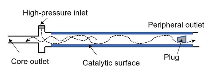
An illustration of such a device is shown in Fig. 1. Pressurized hydrogen enters the tube tangentially forming an intensive vortex that propagates along the tube. In vortex tubes, temperature of the fluid near the walls increases, while temperature in the core flow decreases. If a catalyst is placed on the wall surface, it will encourage para-orthohydrogen conversion. Thus, this tube, if used as a venting device in cryogenic hydrogen storage tanks, will act as a heat sink removing heat from the ullage space.
The present study is a continuation of previous efforts aimed at developing this technology [6]. The main goals of the current investigation are to set up a computational fluid dynamics (CFD) simulation of a hydrogen vortex tube, to validate this modelling against experimental data, and to determine the effective rate coefficient for para-orthohydrogen conversion in catalyzed vortex tubes.
2. Computational Aspects and Geometry
Computational simulations of a cryogenic hydrogen vortex tube are carried out in this study using CFD program STAR-CCM+ of version 2020.2. The finite-volume coupled flow solver utilizes the SIMPLE solution algorithm and the second order upwind convection scheme. The unsteady simulations are based on the first-order implicit stepping in time, but only steady-state results are reported here, corresponding to the states when flow properties are no longer evolving. For computational efficiency, the RANS approach is utilized. The governing equations are based on the continuity, momentum, and energy principles [7],
where t is the time, xi are the Cartesian coordinates, ui are the velocity components, p is the pressure, ρ is the gas density, μ is the viscosity, E is the total energy per unit mass, f is the body force, and qj are the heat flux components.
Several turbulence models have been trialled, and the realizable k-ε model showed better agreement with experiments. In this model, the transport equations for the turbulent kinetic energy k and the turbulent dissipation rate ε are expressed as follows,

where Gk is the turbulent kinetic energy generation term due to the mean velocity gradients, ![]() is the scalar invariant of the strain rate tensor
is the scalar invariant of the strain rate tensor ![]() , ν is the kinematic viscosity, Cε1 and Cε2 are the model coefficients, and σk and σs are the turbulent Prandtl numbers. The turbulent viscosity μt is given as,
, ν is the kinematic viscosity, Cε1 and Cε2 are the model coefficients, and σk and σs are the turbulent Prandtl numbers. The turbulent viscosity μt is given as,

where Cμ depends on turbulent properties and mean flow [8].
Because of large variations of flow properties inside vortex tubes, the two-layer, all-Y+ (blended) option of the turbulence model is adopted. It relies on the wall functions at large Y+ values while resolving more detailed structure of the boundary layer at small Y+ values. Specifics of numerical methods in the program are provided in the STAR-CCM+ manual [9]. Properties of both hydrogen isomers are incorporated into simulations via tables obtained from REFPROP [10].
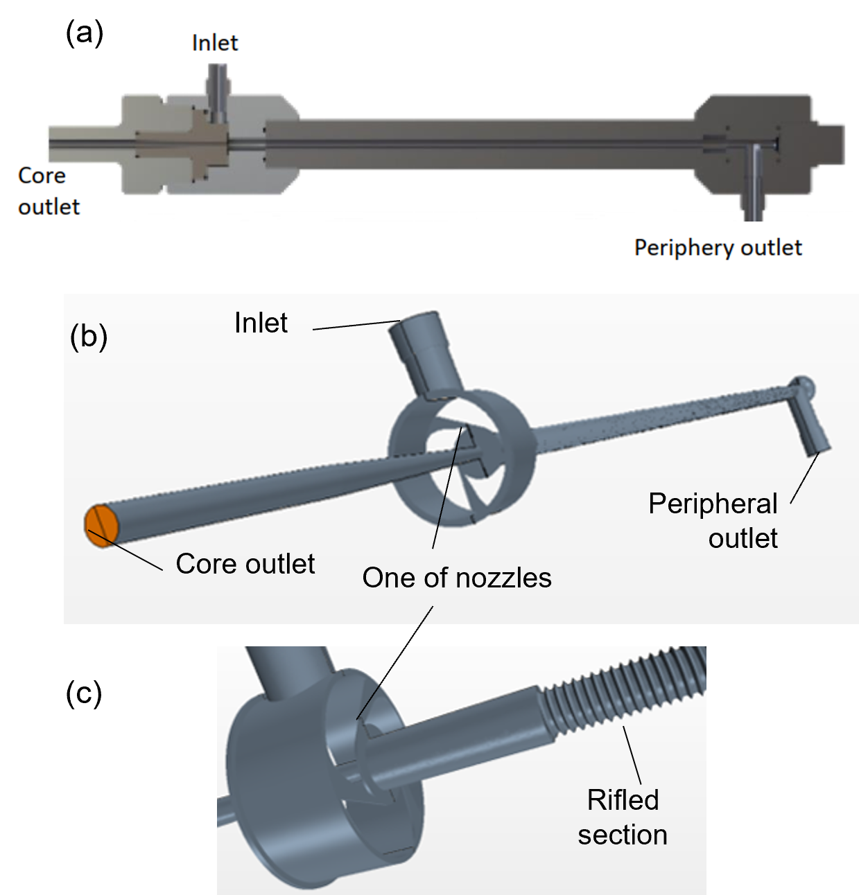
The vortex tube geometry in the numerical setup originates from the experimental study reported by Bunge [11]. A schematic of the experimental device and its CAD models used for CFD are shown in Fig. 2. The vortex tube has an inlet maintained at high pressure from which hydrogen enters tangentially into the tube via three nozzles of combined cross-sectional area of about 0.5 mm2. There are two outlets at the opposite ends of the tube. The core outlet extracts fluid near the tube centreline close to the inlet, whereas the periphery outlet is located far from the inlet. While most vortex tubes have smooth surfaces on the inside, the current setup employed a rifled tube to maximize the surface area covered by catalyst while helping to maintain the vortex further along the tube away from the inlet. The length and averaged diameter of the rifled portion are 180 mm and 3.3 mm, respectively.
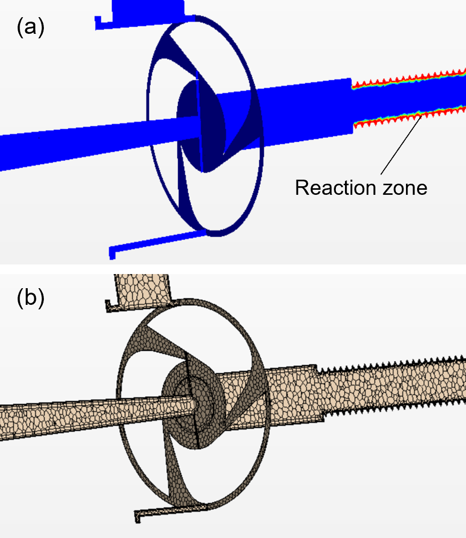
In the catalysed vortex tube experiments, the rifled portion of the internal surface was covered with hydrous ruthenium catalyst [11]. For simplified modelling of catalytic conversion between para- and orthohydrogen states, a thin zone (0.25-mm-thick) in the vicinity of the tube surface was chosen as the reaction zone (Fig. 3a). The rate of conversion was modelled inside this zone using a relaxation-type equation,

where ρort and ρpar are the densities of ortho- and parahydrogen, respectively, t is the time, yort, actual and yort, equil are the actual and equilibrium (at a local temperature) mass fractions of orthohydrogen. The reaction coefficient k was not known in advance. It was determined by matching the CFD prediction of the peripheral temperature to a value recorded in the experiment. According to Eq. (7), the orthohydrogen production rate is proportional to the local density of parahydrogen and depends on how far the mixture is from the equilibrium.
3. Verification and Validation
To establish a suitable numerical grid, a mesh verification study was accomplished using numerical results for the peripheral temperature obtained at three numerical grids of different density in the non-catalyzed tube (Fig. 3b). The experimental conditions included the inlet and core-outlet pressures 56.60 psia and 16.13 psia, respectively, the total mass flow rate of 0.159 g/s, and the inlet and peripheral-outlet temperatures of 53.71 K and 52.70 K, respectively. The constructed numerical grids were of polyhedral type with prism layers near solid surfaces. An illustration of a numerical mesh is shown in Fig. 3b. The computationally predicted reductions of the peripheral temperature with respect to the inlet state were found to be 1.19 K, 0.93 K, and 1.04 K for the coarse, medium and fine grids, respectively. These results demonstrate oscillatory numerical convergence. Using the Richardson extrapolation [7] and the factor of safety [12], the numerical uncertainty was estimated to be 0.10 K. Since this value is greater than the difference between test and numerical results for the peripheral temperature (0.03 K), the numerical approach has been validated.
4. Results and Discussion
To evaluate the effective conversion rate between ortho- and parahydrogen isomers, simulations were conducted for experimental conditions corresponding to a catalyzed tube [11]. In this case, the inlet and core-outlet pressures were 62.03 psia and 15.83 psia, respectively, and the inlet and peripheral-outlet temperatures were 52.81 K and 47.72 K, respectively. While the inlet boundary conditions and the pressure drop are similar to those in the non-catalyzed tube, one can notice much larger observed temperature drop due to cooling caused by the para-orthohydrogen conversion. To attain agreement with this exit temperature, the reaction coefficient k in Eq. (7) was varied, and the numerical value of 210 s-1 was found to produce the best match with experimental data.
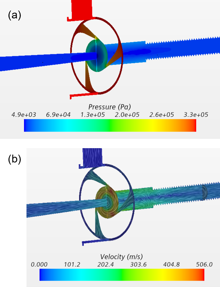
Illustrations of the pressure and velocity fields inside this tube are given in Fig. 4. The pressure is large at the inlet, whereas most of the pressure drop occurs across the nozzles that choke the flow (Fig. 4a). The pressure evolves little inside the tube due to minimal obstruction to the flow in this part of the device.
The velocity is very small at the inlet due to a large cross-sectional area, but it reaches very high values in the nozzles, where Mach number is about one (Fig. 4b). Due to tangential orientation of the nozzles with respect to the main body of the tube, a strong swirl is formed inside the larger portion of the tube. This vortex extends to significant distances away from the nozzles (Fig. 4b). Eventually, at several diameters of the tube away from the nozzles, this vortex dissipates, and the flow becomes primarily axial.
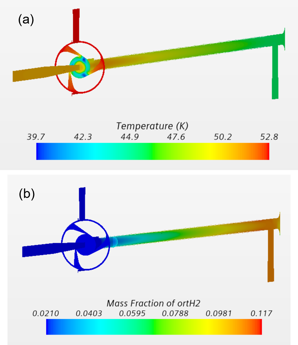
Temperature varies little upstream of the nozzles, as the flow is relatively slow (Fig. 5a). Temperature reaches minimum near the nozzle throats, where the flow reaches sonic speeds, and afterwards, temperature partially recovers due to flow deceleration in the tube section close to the nozzle. However, in the longer rifled portion of the tube, which is covered with a catalyst, temperature starts dropping again due to endothermic conversion of parahydrogen into orthohydrogen occurring near walls due to presence of catalysts.
The distribution of the orthohydrogen fraction in the fluid is illustrated in Fig. 5b. The ortho component in the flow entering the system is about 2.1% Once the fluid reaches the catalyzed portion of the main tube, the para-orthohydrogen conversion is initiated, and the ortho-fraction increases in the downstream direction, reaching about 11% at the peripheral exit.
5. Conclusion
High-speed compressible flow of cryogenic hydrogen was successfully modeled inside a vortex tube. Upon verification and validation study in the non-catalyzed tube, a reactive flow inside a catalyzed tube was simulated. By matching the numerical exit temperature to the experimental value, the effective rate coefficient of para-orthohydrogen conversion was determined to be 210 s-1 for the specific relaxation-type reaction-rate form and the near-wall reaction zone of 0.25 mm. This conversion model can be suggested for approximate simulations of high-speed vortical flow of cryogenic hydrogen undergoing para-orthohydrogen transformation in the presence of ruthenium catalyst. Future extensions of this work can include optimization of practical systems for hydrogen cooling that employ vortex tubes, quantum physics-based modeling of conversion between hydrogen isomers, and validation in broader ranges of experimental conditions.
Acknowledgement
This work was supported by the US Department of Energy under contract No. DE-EE0008429.
References
[1] J. W. Leachman, R. Jacobsen, S. Penoncello and E. Lemmon, "Fundamental equations of state for parahydrogen, normal hydrogen, and orthohydrogen," J. Phys. Chem. Ref. Data, vol. 38, pp. 721-748, 2009. View Article
View Article[2] J. K. Peng and R. K. Ahluwalia, "Enhanced dormancy due to para-to-ortho hydrogen conversion in insulated cryogenic pressure vessels for automotive applications," International Journal of Hydrogen Energy, vol. 38, pp. 13664-13672, 2013. View Article
[3] B. P. Pedrow, S. K. Muniyal Krishna, J. W. Leachman, E. D. Shoemake and K. I. Matveev, "Parahydrogen-orthohydrogen conversion on catalyst loaded scrim for vapor cooled shielding of cryogenic storage vessels," AIAA Journal of Thermophysics and Heat Transfer, vol. 35, no. 1, pp. 142-151, 2021. View Article
[4] K. I. Matveev and J. W. Leachman, "Modelling of liquid hydrogen tank cooled with para-orthohydrogen conversion," Hydrogen, vol. 4, pp. 146-153, 2023. View Article
[5] A. P. Merkulov, Vortex Effect and Its Application in Technology. Moscow: Mashinostroenie, 1969.
[6] C. D. Bunge, K. A. Cavender, K. I. Matveev and J. W. Leachman, "Analytical and numerical performance models of a Heisenberg Vortex Tube," IOP Conference Series: Materials Science and Engineering, vol. 278, 012132, 2017. View Article
[7] J. H. Ferziger and M. Peric, Computational Methods for Fluid Dynamics. Berlin: Springer, 1999. View Article
[8] N. Mulvany, J.Y. Tu, L. Chen and B. Anderson, B., "Assessment of two-equation modeling for high Reynolds number hydrofoil flows," Int. J. Numer. Meth. Fluids, vol. 45, pp. 275-299, 2004. View Article
[9] STAR-CCM+ Manual, 2022. https://www.plm.automation.siemens.com/ global/en/products/simcenter/STAR-CCM.html.
[10] E. W. Lemmon, I. H. Bell, M. L. Huber and M. O. McLinden, NIST Standard Reference Database 23: Reference Fluid Thermodynamic and Transport Properties-REFPROP, Ver. 10.0, Standard Reference Data Program, National Inst. of Standards and Technology, Gaithersburg, MD, 2018.
[11] C. D. Bunge, "A high-fidelity, continuous ortho-parahydrogen measurement and conversion system," Ph.D. dissertation, MME School, Washington State University, Pullman, WA, 2021.
[12] P. J. Roache, Verification and Validation in Computational Science and Engineering. Albuquerque: Hermosa Publishers, 1998.