Journal of Fluid Flow, Heat and Mass Transfer (JFFHMT)
ISSN: 2368-6111

Volume 10 - Year 2023 - Pages 10-18
DOI: 10.11159/jffhmt.2023.002
A Preliminary Investigation on the Geometrical Shape of Pulsating Heat Pipe under Hyper-Gravity Conditions
Cezary Czajkowski1, Andrzej I. Nowak2, Henrik Kassai2, Sławomir Pietrowicz1
1Wrocław University of Science and Technology, Department of Thermodynamics and Renewable Energy Sources
Wybrzeże Wyspiańskiego 27 St., Wrocław, Poland, 50-370
cezary.czajkowski@pwr.edu.pl; an.nowak@pwr.edu.pl; slawomir.pietrowicz@pwr.edu.pl
2Bremen University, Center of Applied Space Technology and Microgravity
Am Fallturm, Bremen, Germany, 28359
henrik.kassai@zarm.uni-bremen.de
Abstract - Many industrial processes require the use of efficient heat-transport devices in challenging environments. One solution is the use of passive devices that utilize multiphase flows. The aerospace sector is one industry where devices operate in normal gravity, microgravity, and hyper-gravity conditions. The study demonstrates the use of two different pulsating heat pipe geometries subjected to normal and hyper-gravity conditions (acceleration from 1g to 8g). The working fluid used was HFE-7000 at volumetric filling ratios of 44% and 66%. The results showed that an appropriate geometrical adjustment improves the performance of the PHP under hyper-gravity conditions, as does a higher volumetric filling ratio.
Keywords: Working fluid, Filling ratio, Rotary system, Pulsating heat pipe, Hyper-gravity.
© Copyright 2023 Authors - This is an Open Access article published under the Creative Commons Attribution License terms Creative Commons Attribution License terms. Unrestricted use, distribution, and reproduction in any medium are permitted, provided the original work is properly cited.
Date Received: 2022-09-03
Date Revised: 2022-10-21
Date Accepted: 2023-01-03
Date Published: 2023-03-21
1. Introduction
The trend in technology development pits the modern world against the challenge of the process of constantly reducing the surface area (miniaturization) while increasing the power of electronic components. In space [1] and aerospace [2] applications, there is the additional issue of the cost of lifting mass, the energy consumption of the installation and operation in a state of weightlessness or overload, which is referred to as micro and hyper-gravity conditions, respectively. In this regard, the pulsating heat pipe, being a passive thermal control solution [3], characterized by the simplicity of its design, lightness, and reliability, meets the sought-after features. A number of factors affecting the heat transfer process which occur in a pulsating heat pipe (PHP), have been described in the literature. One can mention the thermophysical properties of the working fluid, the geometric shape of the flow channel (length of individual sections of the exchanger, number of bends, diameter, etc.) or the conditions under which the device operates (external forces acting on the system). The proposed research work aims to consider the effect of changing the geometric configuration of the PHP, subjected to a variable mass force, on its thermal performance. The generated centrifugal force, acting along the normal to the axis of rotation, having a value greater than the value of gravity in the Earth's gravitational field, changes the conditions of the heat transfer process which occurs inside the PHP. This force acts to a much greater extent on the mass of the liquid, relative to the gas phase, thus disturbing the distribution of the different phases of the working fluid with respect to the direction of acceleration associated with the acting external mass force.

Where D is internal diameter, p denotes density, surface tension and g is the earth gravitational acceleration.
According to the literature, the internal diameter of the flow channel is one of the most important aspects of PHP design [4, 5]. During energy transport, thermal-flow in PHP phenomena is associated with the formation of a two-phase flow structure of the used working fluid. When a certain value of the inner diameter, called the critical diameter is exceeded, surface tension forces become dominated by inertia forces resulting in the forming of a liquid film on the walls in a vertical tube or in stratification and the formation of a free surface in a horizontal tube. Furthermore, once the flow structure is altered, the heat-transport process will deteriorate significantly. In this case, the pulsating heat pipe will act as a thermosyphon, allowing for the transport of energy only in the form of latent heat caused by evaporation phenomena. Accordingly, one of the most cited criteria in the literature [6, 7] is the confinement criterion based on the Bond number, defined as in Equation 1. The dependence described above is discussed not only under the condition of high overload, but also under microgravity conditions. As Abela et al. [8] point out, the same device tested under two conditions: normal gravity and weightlessness, behaves like a thermosyphon for the first case and like a pulsating heat pipe for the second. In 2014, Mameli et al. [9] conducted a study of PHPs under the influence of varying gravity during parabolic flight. The team proved, based on their research, that in microgravity, due to the dynamics of the liquid phase, the confinement criterion based on the Bond number does not have a convergence of analytical results with experimental ones (based on Equation 1, the condition of the capillary diameter for g approaching 0 represents the applicability of any capillary diameter in space). Studies in the sense of a more basic phenomenon, carried out by Nowak et al. [10], were aimed at an experimental investigation on the occurrence of the process of bubble coalescence/brake-up depending on the diameter of the flow channel under microgravity conditions. According to the results of the work, it can be concluded that, despite exceeding the value of the capillary diameter, the process of multiphase flow based on the plug-slug structure occurred (when with the same construction under normal gravity, stratification of the flow structure occurred).
Recently, a few studies have explored the operation of pulsating heat pipes under hyper-gravity conditions. Chen et al. [11] developed a tandem-dual-channel flat-plate pulsating heat pipe (FP-PHP) applicable to hyper-gravity. The authors studied the effect of increasing the centrifugal acceleration acting along the direction of fluid flow in the FP-PHP. Inferring from the study, the team concluded that as the level of overload increases, it has an increasingly negative effect on the quasi-stationary thermo-hydrodynamics in the FP-PHP. Van Es et al. [12] in 2000 conducted a study for various PHP designs on a rotating table. They noted that the ethanol-filled set for the stainless-steel structure allowed stable operation of the device only up to an acceleration of 4.4g. For the second tested solution, based on aluminium and acetone, the device operated stably up to a maximum acceleration equal to 8.4g (the installation limit). In late 2004 and early 2005, Gu et al. [13] proved the possibility of operating a PHP filled with R-114, under hyper-gravity conditions for an overload equal to 2.5g. In 2011 Ma et al. [14] conducted a series of experiments using a rotating table. At that time, the effect of rotational velocity on the thermal performance of the device under test was studied. In their conclusions, the authors indicate that the thermal performance did not change until a maximum acceleration of 10g was achieved. Deng et al. [15] conducted an experimental study of the thermal efficiency of antigravity PHPs, finding that gravity has a significant effect on the thermal fluid processes that take place. According to the conclusions of the work, such a device undergoes a longer start-up process and exhibits more intense quasi-steady-state temperature oscillations, with a higher value of thermal resistance.
The presented research has been conducted at the Center of Applied Space Technology and Microgravity in Bremen while some of the results[1], figures and text were published in the conference proceedings [16]. An experimental campaign was carried out based on the synthetic compound of the 3MTM company under the trade name NOVECTM7000 with a wide application [17].
2. Experimental setup
A pulsating heat pipe test stand containing two bends in the evaporation section was designed and built for hyper-gravity conditions. The setup had to be compact due to the size dictated by the existing infrastructure (centrifuge mounting plate with dimensions of 1000 x 1000 mm), and its visualization is shown in Figure 1.
The experimental system was based on a standard PHP-type passive heat exchanger design, which contains an evaporation section, a condensation section, with a quasi-adiabatic section in between. Two different materials were used in the described solution. The first was copper with 1.5 mm inner diameter capillaries embedded in the upper (condenser) and lower (evaporator) sections. The same bending radius of 35 mm was kept for all bends. In the quasi-adiabatic section of the pulsating heat pipe, four glass tubes (borosilicate glass, length of 145 mm, wall thickness of 2.5 mm) were mounted, which had two functions: the first was partial insulation from ambient conditions, and the second was the ability to record an image associated with the flow structure of the working fluid during the energy transport process between media. Such a solution made it possible to obtain a field of view with a width of 115 mm (two central tubes with mirrors were observable). All the components, once connected and assembled, enabled a high-quality vacuum to be maintained.
Table 1. The geometrical configuration of the PHP.
|
Geometrical parameters of the studied PHP |
||
|
PHP material |
Copper and Glass |
|
|
Internal diameter, mm |
1.5 |
|
|
External diameter, mm |
3.5 |
|
|
Number of bends, - |
2 |
|
|
Total length, m |
2.05 |
|
|
Evap./Cond. sec. length, m |
0.54/0.70 |
|
Table 2. The selected operating parameters of the PHP.
| Operating parameters | |
|
Working fluid, - |
HFE-7000 |
|
Heat flux, kW/m2 |
3.25 |
|
Filling ratio, % |
44 and 66 |
|
Acceleration, m/s2 |
≤8g |
Bent direction, - |
A and B |
What distinguishes the presented design from the commonly used ones is the possibility to change the position of the bent elements of the evaporation section (see: shown in Figure 1 position "-B", and possible: "A" and "B"). Experimental tests were carried out according to the design of the measurement campaign, which considered the installation of bent u-shaped elements: along the direction ("B") and perpendicular ("A") direction to the vector of the external mass force acting on the system (shown in Figure 4). The heat transfer process was applied by converting electricity to heat energy using a DC (Direct Current) power supply with a GPIB (General purpose interface bus) port (6675𝐴, Agilent Technologies, USA) and a jacketed resistance wire (Mi series Inconel600, 0.89 mm) tightly wrapped around the outer wall of the evaporation section capillaries. In order to minimize the impact of ambient conditions on the measurement system, two types of insulation were used, i.e. static based on a double layer of polycrystalline wool with mullite and corundum (ALSIFLEX®, at 800 °C, 10 mm thickness of one layer) wrapped with Teflon tape, and dynamic insulation consisting of a plastic shield to prevent the intensification of heat transfer during rotation of the Large Scale Centrifuge (LSC) arm.
The condensation section was based on a water system due to the possibility of connecting to the cooling water network of the entire campus. For this reason, a flow tank made of PETG (Polyethylene Terephthalate Glycol) was embedded into the upper part of the exchanger, in which the inlet water temperature was maintained at 8 ℃ for a volumetric flow rate of 3.5 l/min controlled by an ultrasonic flow meter (Flowmax 44𝑖). A steel capillary port built into the left side of the system was used to operate the exchanger, i.e., degassing/filling the system with working fluid using a valve (Index Health & Science, 𝑃 − 732 and 𝑃 − 446), while a threaded port for a pressure transducer (𝐴−10, WIKA Instrument Lp, Poland) was used on the right side to measure the pressure inside the capillaries. The dimensions of the tested PHP are shown in Table 1, while selected working conditions are shown in Table 2.
In order to determine the thermal performance of the device, depending on the current value of the external mass force acting on the system, the condensation and evaporation sections were equipped with "T" type thermocouples (diameter of 0.1 mm, accuracy of ±0.5 ℃). Seven temperature sensors were mounted in the first section, and six in the second. The measuring points were arranged so that determination of the flow direction inside the capillaries could be confirmed. The control and measurement systems were built based on the LabView environment and with National Instruments (NI) components. Due to the rotational movement of the Large Scale Centrifuge, data acquisition had to be partially carried out wirelessly by means of a 4-slot CompactRIO Controller (cRIO 9032).
3. Experimental campaign
The measurement campaign was carried out on a rotating machine (Large Scale Centrifuge), which allows for testing of up to 30g (Figure 3c). The elements of the setup were mounted in three main locations of the facility. The first one being an experiment platform, a so called “swing”, with a 10 mm thick mounting plate. Here, the experimental setup (Figure 3a) was installed along with the cooling water supply system, the data acquisition system, and the imaging system (Phantom Miro eX4 high-speed camera and background LED panel) and acceleration sensors (Honeywell QA-1400). The second location was the center of the rotating machine, where a DC power supply was mounted along with a control and measurement system, developed in LabView software (Figure 3b). The last location is the control room, underneath the rotating device, from which the test procedure was managed. The presented test results are limited to acceleration of up to 8g due to overpressure in the tank resulting from the machine's rotary motion and the resistances associated with hydrostatic pressure corresponding to the machine arm (approximately 6.5 m).
Table 3. Certain thermodynamic properties of the working fluid at a temperature of 25℃ [15].
|
Parameter, Unit |
HFE-7000 |
|
Chemical formula, - |
C3F3OCH3 |
|
Boiling point, oC |
34 |
|
Saturation pressure, kPa |
64.6 |
|
The latent heat of evap., kJ/kg |
142 |
|
Liquid density, kg/m3 |
1400 |
|
Vapour density, g/m3 |
510 |
3.1. Operation conditions
One of the most influential parameters on the thermal efficiency of a device is the selection of the working fluid. The filling ratio and thermophysical properties of the medium, such as specific heat, enthalpy of vaporization, density, viscosity, surface tension, boiling point, etc. determine the performance and operating conditions of the device [18]. Experimental studies were carried out with the working fluid NOVEC™ 7000 (3M™) and Table 3 presents its thermo-physical properties.
Table 4. Values of rotational speed with applied intervals.
|
Interval, s | 2ax+, m/s2 |
|
1200 |
2g |
|
480 |
4g |
|
480 |
6g |
|
480 |
8g |
|
480 |
7g |
|
480 |
5g |
|
480 |
3g |
|
480 |
1g |
The set of planned tests provides for the change of three parameters such as rotational speed (and thus the gravitational field), filling ratio, and bending direction. Each test aims to obtain a quasi-steady state for the heat transfer process with a gradual change of the indicated parameters such as the change in filling ratio between 44% and 66%, the acceleration in the range of from 1g to 8g as shown in Table 4 and the situational settings of the stand in Figure 4. The centrifugal acceleration, which can be found in Table 3, is measured by an acceleration sensor which is normally maintained in a range of ±0.05g.

Where ω is the angular velocity and rc denotes rotating radius.
The resulting acceleration is the resultant of the rotational speed and radius of rotation according to Equation 2. It is worth noting that the centrifuge allows the setup to be mounted on a swinging platform. In this way, the resultant force is always directed perpendicular to the setup.
3.1. Data accuracy
When describing the control and measurement system, special attention should be paid to the accuracy and uncertainty of the performed measurement. The pressure transducer had a measurement nonlinearity, according to BFSL, of 0.5%, and a maximum deviation of the zero point of 0.8% with a measurement accuracy of 1%. The flowmeter allowed for the measurement of conductive and non-conductive liquids with an absolute accuracy of 0.3 L/min. Other errors associated with the experiments are summarized in Table 5. The error analysis results presented are the same as in Czajkowski et al. [18] since the same test apparatus was used.
Table 5. Absolute and relative errors with the formulas [19].
|
Abbr.. |
Abs. |
Rel., % |
Formula |
| δU |
±120 mV |
±0.04 |
|
| δI |
±12 mA |
±0.10 |
|
| δT |
±0.5 oC |
±0.40 |
|
| δ(ΔT) |
±0.7 oC |
±2.33 |
√δTe2+ δTc2 ) |
| δQ |
±5 W |
±0.25 |
√(δU/U)2+(δI/I)2 |
| δR |
±4.7⋅10-4 K/W |
±2.35 |
√((δ(ΔT)/ΔT)2+〖(δQ/Q)2 ) |
| δax+ | ±0.05 g |
±2.50 |
4. Summary
The test stand provides the ability to measure temperature and pressure during the device operation in an axial rotating system. The condensation section could be successfully water-cooled during the campaign. The thermal efficiency of the PHP was analyzed based on the thermal resistance calculated from Equation 3.

Where ![]() ,
, ![]() is the average temperature of the evaporation and condensation sections, respectively (signals from the sensors as shown in Figure 4). Q denotes the heat power supplied. The two parameters given by the DC power supply for the Equation 4 were used to calculate the heat output.
is the average temperature of the evaporation and condensation sections, respectively (signals from the sensors as shown in Figure 4). Q denotes the heat power supplied. The two parameters given by the DC power supply for the Equation 4 were used to calculate the heat output.

Where U is the voltage, and I denote current. In this section, two cases are presented, namely a straight U shape (see Figure 4 version "A") and a bent U-shape (see Figure 4 version "B"). Tests were carried out for a volumetric filling ratio (FR) equal to 44% and 66%. The results are summarized in four pairwise graphs for the corresponding cases of the experiment setup. All of the tests presented were carried out under the same conditions for the evaporator![]() .
.
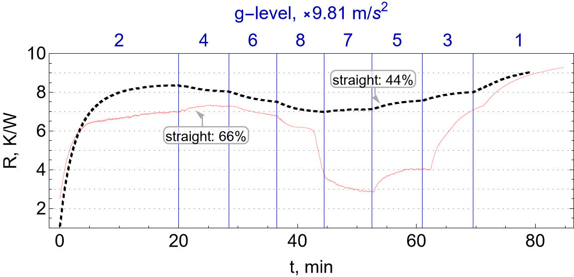
Figure 5 shows tests for straight U-shapes with different filling ratios. The case for FR=44% resulted in a high thermal resistance value, approximately R=7 K/W, throughout the experimental range. The higher filling ratio (FR=66%) resulted in a lower thermal resistance value over the entire range of tests. Importantly, around ax+=8g, one can observe a start-up of the device characterized by a drastic decrease in thermal resistance, approximately R=3 K/W. Based on the results obtained, it can be considered that the optimal operating conditions of the pulsating heat pipe occurred in the range of 5≤ax+≤8g, however, special attention should be paid when comparing the process of overload increase and decrease. After 25min of testing, when an overload of 6g was applied, the PHP responded with a decrease in thermal resistance, but this decrease did not show any significant change in the thermal-flow process (no start-up conditions). This provides the information that the heat transfer process is not taking place efficiently. Another interesting case can be observed during the acceleration decrease, when a 5g overload was applied after 50 minutes of testing. The PHP was characterized by a very low value of thermal resistance, which indicates its efficient operation and quasi-steady state for energy transport conditions (flattening of the thermal resistance function during about 60min of testing). In summary, for a filling ratio of 44%, the PHP was not characterized by typical start-up phenomena, whereas for 66%, a characteristic start-up appeared. Furthermore, it should be noted that for a filling ratio of 66%, a certain optimum value of gravitational acceleration exists, but it was only possible to register during the reduction of the gravitational acceleration value.
In the second case, during the measurement campaign, the effect of bending was checked for the worst case presented, which was the lower filling ratio. As can be seen from Figure 6, the use of a bend in the evaporation section along the direction of the acceleration vector associated with the centrifugal force, has a positive effect on the heat transfer process. The start-up conditions can be observed for a bend as low as 4g (a decrease despite the low value of the derivative of the thermal resistance function over time), while, as described in an earlier paragraph, the straight section did not show any change in its working characteristic. The test bench equipped with a bend exhibited a quasi-steady state of up to 5g.
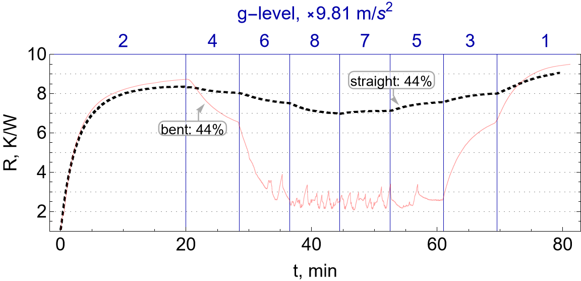
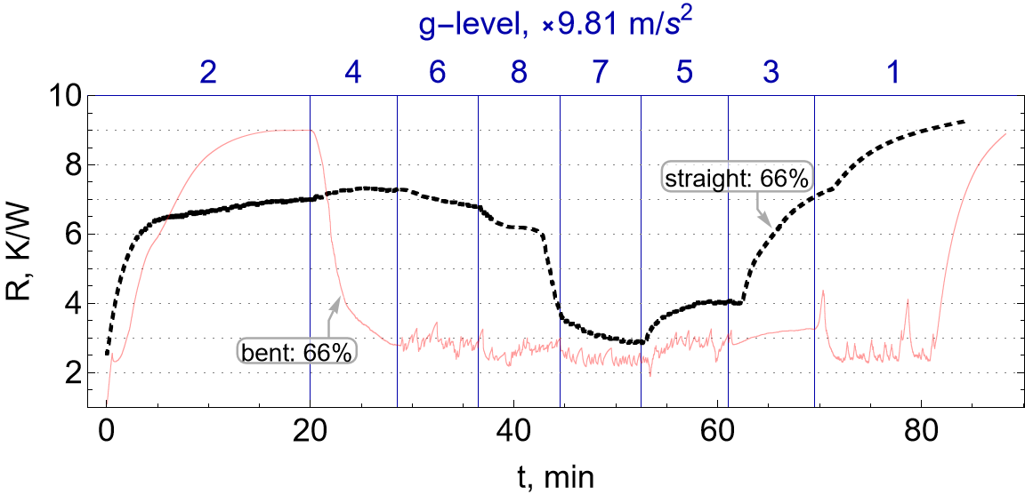
Figure 7 shows an analogous case to that described in the previous paragraph, but with a higher filling ratio. When the results are compared with each other, the higher FR results in a significant expansion of the pulsating heat pipe's operating range under conditions characterized by low thermal resistance. It should be noted that thermal resistance over the entire range studied is smaller for a bending U-shape compared to a straight U-shape (excluding pre-start-up conditions up to 2g). Increasing the filling ratio results in a faster start-up process in the vicinity of 4g (compared to the case of bending with lower FR) as evidenced by the higher value of the function derivative and the quasi-steady state conditions between 6g and 5g. The conditions corresponding to the 3g acceleration are a clear disruption of the process, but with a slight increase in thermal resistance. Furthermore, ax+ = 1g might seem to result in maintaining the effective heat transfer process, but after 80 min of testing one can see a sudden break in the process and an increase in thermal resistance corresponding to dry-out conditions. Thus, it should be assumed that the optimal operating conditions for the exchanger equipped with a bent U-shape, for higher FR, were obtained in the range of 4g≤ax+≤8g.
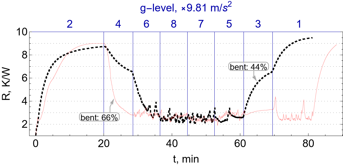
To conclude the discussion of the results obtained, Figure 8 is included, showing a comparison of two bending cases with different filling ratios. The first difference that can be observed is the value of the derivative of the thermal resistance function in time for the start-up and rupture (sudden dry-out) process corresponding to an overload of 4g and 3g, respectively, in both cases studied.
A higher FR means faster stabilization of the process, and a faster response (start-up process) of the system to a change in external conditions affecting the installation, while the opposite situation can be observed for the rupture. A smaller filling ratio is associated with a clear limit in the optimal operating conditions of the pulsating heat pipe, accompanied by a sudden increase in the thermal resistance of the heat exchanger. In both cases, a similar thermal resistance value was obtained around 3 K/W at the highest overload.
According to the results, the generated body force, acting along the normal to the axis of the PHP adiabatic section, having a value higher than the value of gravity in the Earth's gravitational field, influences the conditions of the heat exchange process. The parameters tested, such as the filling ratio and bent direction of the evaporation section have a significant impact on the thermal flow phenomena that occur [13]. During tests based on HFE-7000 as a working fluid inside a pulsating heat pipe with a diameter of 1.5 mm, it was shown that for a non-inertial environment, higher FR and the geometric shape of the bends of the evaporator sections have a significant effect on the heat exchanger's thermal performance. It should be noted that in the matter of experimental operations, the effect of the implementation direction of the test process, that is, the increase or decrease in the value of the external force acting on the system, must be confirmed. Ultimately, the results show that by appropriately shaping the pulsating heat pipe, it is possible to increase its efficiency especially when operating at high overload values.
These results are only an indication and the beginning of further studies to be done in the field of the effect of the acting mass force on the operation of a pulsating heat pipe. It is necessary to carry out such an analysis of the effect of changing the working medium, its filling ratio, the internal diameter of the capillaries and the range of higher overloads (up to 30g), as well as to carry out a visual analysis of the flow structure of the working fluid.
Acknowledgements
The preliminary test work was realized thanks to the support of Center of Applied Space Technology and Microgravity, Bremen University, and by the internal research funds of the Department of Thermodynamics and Renewable Energy Sources at Wrocław University of Science and Technology, Poland, No. 821110160 (MPK 9090750000). Participation in the conference was financially supported by Polish Oil Mining and Gas Extraction S.A. based on the 5th edition of the "Young Innovators for PGNiG" competition.
References
[1] Mauro Mameli, Giorgio Besagni, Pradeep K. Bansal, Christos N. Markides, "Innovations in pulsating heat pipes: from origins to future perspectives" in Applied Thermal Engineering, vol. 203, 2022. View Article
View Article[2] Qian Su, Shinan Chang, Mengjie Song, Yuanyuan Zhao, Chaobin Dang, "An experimental study on the heat transfer performance of a loop heat pipe system with ethanol-water mixture as working fluid for aircraft anti-icing," in International Journal of Heat and Mass Transfer, vol. 39, Pages 280-292, 2019. View Article
[3] Przemysław Smakulski, Sławomir Pietrowicz, "A review of the capabilities of high heat flux removal by porous materials, microchannels and spray cooling techniques.", in Applied Thermal Engineering, Vol. 104, 2016. View Article
[4] Chih-Yung Tseng, Kai-Shing Yang, Kuo-Hsiang Chien, Ming-Shan Jeng, Chi-Chuan Wang, "Investigation of the performance of pulsating heat pipe subject to uniform/alternating tube diameters" in Experimental Thermal and Fluid Science, vol. 54, Pages 85-92, 2014. View Article
[5] Jiansheng Wang, Yu Pan, Xueling Liu, "Investigation on start-up and thermal performance of the single-loop pulsating heat pipe with variable diameter" in International Journal of Heat and Mass Transfer, vol. 180, 2021. View Article
[6] Yu-Hsing Lin, Shung-Wen Kang, Tsung-Yu Wu, "Fabrication of polydimethylsiloxane (PDMS) pulsating heat pipe.," in Applied Thermal Engineering, pp. pp. 573--580.
[7] Aline Dell'innocenti, Stéphane Lips, Valérie Sartre, Nicolas Blet, Jérôme Coulloux, Jocelyn Bonjour "Thermal Performance and Operating Regimes of a Flat Pulsating Heat Pipe for the Temperature Homogenization," in ASME Journal of Heat Transfer, 2019.
[8] Mauro Abela, Mauro Mameli, Vadim Nikolayev, Sauro Filippeschi, "Experimental analysis and transient numerical simulation of a large diameter pulsating heat pipe in microgravity conditions" in International Journal of Heat and Mass Transfer, vol. 187, 2022. View Article
[9] M. Mameli, L. Araneo, S. Filippeschi, L. Marelli, R. Testa, M. Marengo, "Thermal response of a closed loop pulsating heat pipe under a varying gravity force," in International Journal of Thermal Sciences, pp. 11-22, 2014. View Article
[10] Andrzej I. Nowak, Luca Pietrasanta, Cezary Czajkowski, Marco Marengo, Sławomir Pietrowicz,"Bubble coalescence and break-up in confined oscillating two-phase flows under microgravity conditions" in International Journal of Heat and Mass Transfer, vol. 192, 2022. View Article
[11] Xi Chen, Xiangdong Liu, Dehao Xu, Yongping Chen, "Thermal performance of a tandem-dual-channel flat-plate pulsating heat pipe applicable to hypergravity" in International Journal of Heat and Mass Transfer, vol. 189, 2022. View Article
[12] J. van Es, A. A. Woering, "High-acceleration performance of the flat swing-ing heat pipe," in International Conference On Environmental Systems, 2000. View Article
[13] M. K. R. F. J. Gu, "Effects of gravity on the performance ofpulsating heat pipes," in Journal of Thermophysics and Heat Transfer, p. 370-378, 2004. View Article
[14] Hongbin Ma, Scott M. Thompson, Aaron A. Hathaway, Chris D. Smoot, Corey A. Wilson, Robert M. Young, Lawrence Greenberg, Brian R. Osick, Stephen Van Campen, Brian C. Morgan, Darin Sharar, Nicholas Jankowski, "Experimental Investigationof a Flat-Plate Oscillating Heat Pipe During High-Gravity Load," in Heat and Mass Transport Processes, vol. 10: Parts A and B, p. 27-632, 2011.
[15] Zilong Deng, Yi Zheng, Xiangdong Liu, Bingpeng Zhu, Yongping Chen, "Experimental study on thermal performance of an anti-gravity pulsating heat pipe and its application on heat recovery utilization," in Applied ThermalEngineering, p. 1368-1378, 2017. View Article
[16] Cezary Czajkowski, Andrzej I. Nowak, Sławomir Pietrowicz, Henrik Kassai, "Geometrical shape of pulsating heat pipe under hyper-gravity condition" in Conference: Proceedings of the 8th World Congress on Mechanical, Chemical, and Material Engineering (MCM'22), 2022. View Article
[17] Chao Dang, Li Jia, Qi Peng, Liaofei Yin, Zhuoling Qi, "Comparative study of flow boiling heat transfer and pressure drop of HFE-7000 in continuous and segmented microchannels," in International Journal of Heat and Mass Transfer, 2020. View Article
[18] Cezary Czajkowski, Andrzej I. Nowak, Agnieszka Ochman, Sławomir Pietrowicz, "Flower Shaped Oscillating Heat Pipe at the thermosyphon condition: Performance at different rotational speeds, filling ratios, and heat supplies" in Applied Thermal Engineering, 2022. View Article
[19] Cezary Czajkowski, Andrzej I. Nowak, Przemysław Błasiak, Agnieszka Ochman, Sławomir Pietrowicz, " Experimental study on a large scale pulsating heat pipe operating at high heat loads, different adiabatic lengths and various filling ratios of acetone, ethanol, and water" in Applied Thermal Engineering, vol. 165, 2020. View Article