Journal of Fluid Flow, Heat and Mass Transfer (JFFHMT)
ISSN: 2368-6111

Volume 9 - Year 2022 - Pages 184-190
DOI: 10.11159/jffhmt.2022.022
Numerical Modelling Of Liquid Film Deposition from Moving Meniscus in a Capillary Tube
Alihossein Nikkhah1, Nooshin Karami1, Albert Tessier-Poirier1, Omid Abouali2, Luc G. Fréchette1
1Institut Interdisciplinaire d’Innovation Technologique (3IT), Univ. de Sherbrooke
Sherbrooke, QC, Canada
Alihossein.Nikkhah@usherbrooke.ca; Nooshin.Karami@usherbrooke.ca; Albert.tessier-poirier@usherbrooke.ca
2School of Mechanical Engineering, Shiraz University, Shiraz, Iran
abouali@shirazu.ac.ir
@someuniversity.edu
Abstract - Meniscus motion in a capillary tube is a very common type of flow in thermal management devices such as oscillating and pulsating heat pipes. It is well known, that the thin film deposited on the wall, which is due to liquid shear force, plays a major role in the heat and mass transfer of those devices. This study focuses on the hydrodynamics of this flow using a CFD axisymmetric model of a 1mm diameter capillary, with the approach of the volume of fluid (VoF). The CFD-VOF approach is tuned to capture the liquid film deposition from a receding meniscus at different constant velocities. Due to the high required grid resolution, the moving overset mesh technique is used. In doing so, a fine-meshed domain consists of meniscus slides over the background domain with a coarse mesh. By using this technique, the number of cells and computational time are reduced considerably in comparison with the regular meshing approach. With water as a working fluid, the numerical results for the liquid film thickness, at different velocities, compare well with experimental data from the literature. The simulations also show that at a higher capillary number, the axial location where the film thickness becomes constant moves away from the meniscus nose. The shear stress distribution indicates higher values near the meniscus compared to uniform film and liquid plug zones which is due to the interface curvature in this zone. Also, a recirculating flow was observed within the liquid film left behind the receding meniscus which could have favorable effects in terms of heat and mass transfer. The present work on hydrodynamics is the first step toward complete modeling of an oscillating meniscus with mass and heat transfer inside the capillaries.
Keywords: Computational fluid dynamic (CFD), overset grid, self-oscillating fluidic heat engine (SOFHE), Oscillating heat pipe (OHP), wetting dynamic.
© Copyright 2022 Authors - This is an Open Access article published under the Creative Commons Attribution License terms Creative Commons Attribution License terms. Unrestricted use, distribution, and reproduction in any medium are permitted, provided the original work is properly cited.
Date Received: 2022-10-04
Date Accepted: 2022-10-20
Date Published: 2022-11-09
1. Introduction
Thermal management devices such as oscillating and pulsating heat pipes (OHP and PHP)[1], [2] as well as recent thermofluidic energy harvesters such as SOFHE[3], are two-phase flow devices that include moving menisci and employ phase transition (evaporation and condensation) for operation. Generally, there are two main physical phenomena in the study of SOFHE and OHP/PHP, which are the hydrodynamic aspects as well as the exchange of heat and mass transfer between phases. Understanding these aspects is the keystone in improving the performance of these devices.
Regarding the hydrodynamic aspects, a liquid film is left on the wall as a meniscus recedes in a capillary tube, due to viscous shear forces. This liquid film plays a major role in the operation of those devices as it provides the available liquid with low thermal resistance for evaporation [4]–[7]. With the assumption of a flat surface over the liquid film on the wall, the lubrication approximation of the hydrodynamics equation yields acceptable results in terms of film thickness[8]. However, this assumption fails to be valid for the meniscus and the de-wetting ridge due to the curvature of the film, and its validity is also questionable for the evaporating liquid film. As a result, higher-order
numerical approaches like CFD are required to capture the more complex flow features. However, CFD modelling of meniscus motion and film deposition can be very time-consuming as it requires high grid resolution, especially in the case of large distance movement or amplitude of the meniscus. To the best of our knowledge, no specific CFD modelling of meniscus wetting dynamics inside a capillary has been presented in the literature.
The purpose of the current research is to define a CFD model which is capable of capturing the wetting dynamics of a receding meniscus, focusing on the liquid film thickness left on the wall. In doing so, the CFD technique with the approach of the volume of fluid (VoF) has been used, in combination with a moving mesh. The numerical results of the liquid film thickness left behind receding meniscus at different constant velocities have been validated with experimental data reported in the literature [9] to tune the hydrodynamic CFD model. Instead of using high grid resolution along the length of the capillary, the moving overset grid approach is used to follow the meniscus region to reduce the number of cells and the computational time. This is the first step toward accurate CFD modelling of oscillating meniscus with phase transition.
2. Physical model
2.1. Governing equations and constitutive relations
The volume of fluid (VOF) is a multiphase modelling approach used for modelling of dominantly immiscible fluids which have clear interfaces between them. In the current modelling, there are two phases, water and air, in contact in a capillary tube, and their interface (meniscus) is assumed to be continuous and immiscible. In this regard, the VOF technique is used to track the meniscus. In doing so, the parameter of volume fraction,αi, is introduced and assigned to each phase, which is the volume fraction of a cell occupied by phase i (liquid water or air). According to their definitions, the volume fractions in each computational cell sum to unity Eq. (1). The cells on the interface are occupied by both liquid water and air phases while on the two sides of interface, ideally, it’s supposed to have only one phase. As in single-phase laminar flow, here a single momentum set of equations Eq. (2) and a continuity equation Eq. (3) are solved for the entire domain. However, the way the fluid properties are calculated as well as the interface force source term ![]() in the momentum equation Eq. (2) distinguishes it from a single-phase flow.
in the momentum equation Eq. (2) distinguishes it from a single-phase flow.


For the fluid properties in Eqs. (2)-(3), the volume average of the existing fluid phase’s properties is used in each computational cell as in Eq. 4. For this purpose, the phase’s volume fractions are required, which necessitates adding another continuity equation for one of the phases (Eq. (5), so- called interface tracking equation). This phase is referred to as a secondary phase, and chosen as the liquid water in the current research.
Moreover, air phase is considered as an ideal compressible gas, which obeys the perfect gas law. The source term ![]() in the momentum balance equation is considered to capture the effect of the surface tension which was proposed by Brackbill [10] and acts when both phases are present at a computational cell. Surface tension is applied at the interface, and is converted to a volume force Eq. (6) by applying the divergence theorem to use it in the momentum equation as a source.
in the momentum balance equation is considered to capture the effect of the surface tension which was proposed by Brackbill [10] and acts when both phases are present at a computational cell. Surface tension is applied at the interface, and is converted to a volume force Eq. (6) by applying the divergence theorem to use it in the momentum equation as a source.
2.2. Domain discretization and boundary conditions
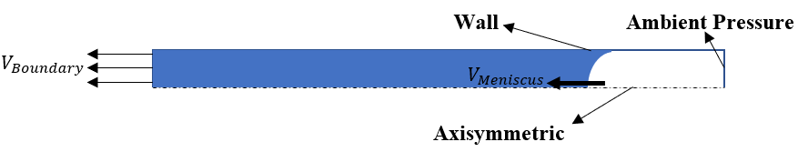
The physical domain consists of an axisymmetric model of the tube cross-section with the boundary conditions shown in figure 1. As shown in this figure, the velocity boundary condition is set at one opening of the pipe to mimic the liquid plug at a specified rate to achieve the desired meniscus velocity. The open end of the pipe is set at ambient pressure.
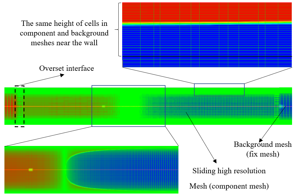
As the governing equations cannot be solved analytically, they will be discretized in time and space to form a set of equations that are solved by the appropriate approaches in computation fluid dynamics. To do so, the computational domain consists of a 0.5mm×100mm rectangle representing an axisymmetric section of a circular tube, discretized into small cells. As a result, there is no real sharp interface between the two immiscible fluids but the interface has a finite thickness depending on the grid resolution. Although with higher grid resolution, the results are more accurate, the computational time is also higher which is not desired. To address this problem, the overset technique is used. As indicated in figure. 2, the moving meshed box which has the priority for computations to be done on slides over a background mesh and follows the meniscus to enhance the accuracy near the high gradient of volume fraction regions. In this regard, the gradient of volume fraction far enough from the meniscus is normal to the wall [8] so there is no need to have a high-resolution mesh parallel to the wall. The data transfer between the component and the background meshes is performed through the overset interfaces where both fine and coarse meshes of the component and background meshes exist at the same time. A boundary layer meshed zone is considered normal to the wall in both component and background meshes which coincide with the direction normal to the wall to avoid the interpolation of the flow data in that direction.
2.3. Numerical procedure
Ansys Fluent 19R3 solver with the volume of fluid method has been used to model the liquid film deposition on the wall. In this regard, the pressure-velocity coupling is obtained by the implicit method of coupled in the solver as it is currently the only compatible approach with the overset grid. The PRESTO scheme is used for the pressure interpolation and the schemes of second order upwind and Geo-Reconstruct are used for discretizing the momentum and volume fraction equations, respectively. To follow the meniscus, the sliding component grid moves over the background mesh according to the location of the maximum absolute value of the volume fraction gradient on the axis of the tube. A user-defined function (UDF) has been developed to control the motion of the sliding component. A variable time-stepping method is used for the transient simulation based on the value of 0.5 for the global Courant number. As a result, the time step size is smaller for higher meniscus velocity, which is desired.
3. Results and discussion
3.1. Validation of numerical results
The accuracy of the numerical results is validated by comparison with experimental data for the liquid film thickness, reported at steady conditions by Youn et al. [9].
To compare the numerical results with the experimental data, in addition to material properties and the tube geometry, the meniscus velocity should be the same for both cases. However, the meniscus velocity, which is the main dynamic property affecting the film thickness, is a part of the solution not an input in the CFD analysis and is determined iteratively by trying different values for boundary velocity, Ub (the velocity at pipe inlet which is an input in CFD and equal to mean volumetric velocity). As shown in figure 3, the obtained numerical velocities, Um_numerical, for the meniscus are very close to the measured experimental data, Um_experimental. So, the numerical and experimental results for the film thickness are comparable. Figure 3 also shows the diagram of the boundary velocity Ub, versus the meniscus velocity, Um. Due to the deposited liquid film on the wall, Um is always higher than U¬b to make the mass of liquid conserved.
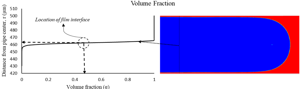
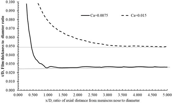
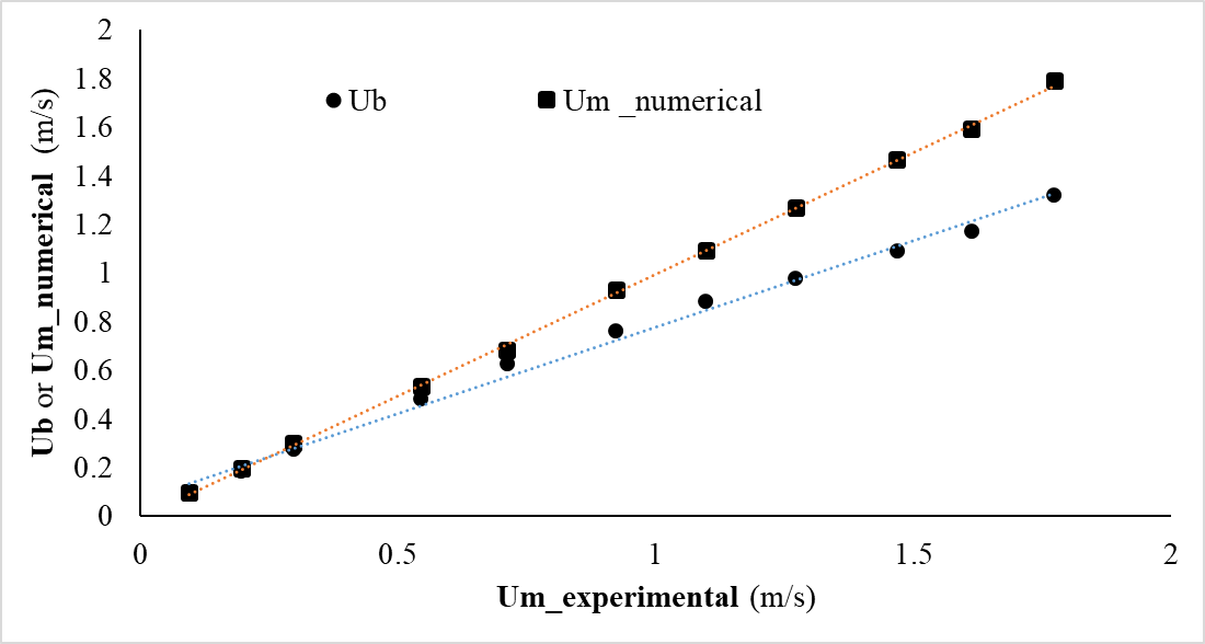
Figure 6, shows the numerically predicted film thickness in comparison with the experimental. The analysis is limited to Reynolds number, Re, of less than 2000 beyond which the flow becomes turbulent. The results show an excellent match between numerical and experimental results with a maximum error of less than 20 percent.

3.2. Flow pattern and shear stress
The deposited liquid film is the result of a force balance between the shear and surface tension forces. In fact, the liquid shear stress on the wall is responsible for the film deposition while the surface tension force tries to keep the liquid from distributing. In terms of the shear stress underneath the liquid plug and its extension on the wall, there are three different zones as depicted in Fig. 6 including Developed, Meniscus transition, and Film zones.
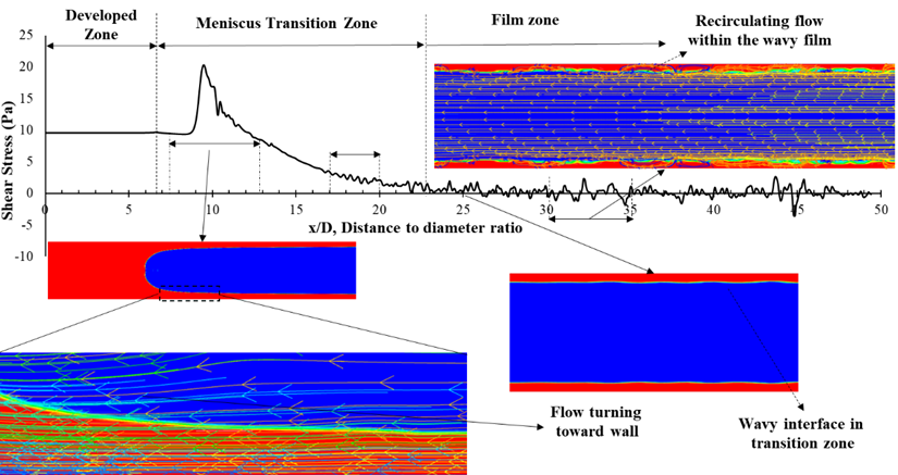
In the Developed zone, which is within the liquid plug, the flow is like a single-phase flow with finite shear stress whose contribution to the total friction depends on the length of the liquid plug. An increase in the shear stress in the Meniscus Transition zone is observed, which is due to the meniscus curvature.
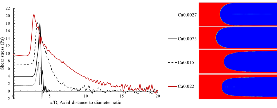
In addition, the axial location of the initial film thickness is four diameters away from the meniscus nose at Ca=0.015 while it reduces to almost one diameter away at Ca=0.0027. This indicates that the shear force has a longer effective range at higher capillary numbers.
This kind of recirculating flow is especially observed in the thicker liquid film which corresponds to higher capillary numbers. As shown in Fig. 6 the curvature of the meniscus makes the flow deviate toward the wall and increases the axial velocity in this region. Moreover, the wavy shape of the interface, makes the shear profile fluctuate slightly. In addition, there are some recirculating flows within the film zone far from the meniscus nose in the deposited liquid film which leads to a locally negative profile of the shear stress number. Recirculation of flow within the film zone was observed before [11] and could be a favorable phenomenon in terms of heat and mass transfer within the film region since it reduces the thermal resistance of the liquid film.
At low capillary numbers, as shown in Fig. 7, the air momentum above the liquid film is not enough to pull the liquid film and that’s why it’s almost immobile with near zero shear stress underneath. However, at higher capillary numbers, the film thickness is thicker and due to the inertia, the liquid velocity as well as the shear stress profile approaches zero more gradually. Besides, as presented in Fig. 7 the transition region from the meniscus to the film region is more gradual.
5. Conclusion
The CFD method with the approach of VoF was used to capture the deposited film behind a laminar receding meniscus in a capillary tube. Due to the requirement of a high grid resolution near the interface, the over set technique with a finite length moving domain of high grid resolution was used, to follow the meniscus to reduce the total number of computational cells and the computational time. The numerical results in terms of film thickness show a very good match in comparison with the experimental data which means the CFD-VoF coupled with the overset grid generation yields acceptable results for the wetting dynamics of such a flow. Moreover, the shear stress profile shows peak values near the meniscus and gradually drops down to zero in the film region. However, in the film region, some flow recirculation was observed which makes the shear profile fluctuate between small negative and positive values. The recirculating flow within the film region could have a favorable effect on the heat and mass transfer within that region. This is the first step toward complete and accurate modeling of an oscillating meniscus in a capillary tube, which includes mass and heat transfer as well.
References
[1] W. Jiansheng, W. Zhenchuan, and L. Meijun, “Thermal performance of pulsating heat pipes with different heating patterns,” Applied Thermal Engineering, vol. 64, no. 1–2, 2014, doi: 10.1016/j.applthermaleng.2013.12.004. View Article
[2] "Oscillating Heat Pipes."
[3] A. Nikkhah, A. Tessier-Poirier, N. Karami, O. Abouali, and L. G. Frechette, "Investigation of the Liquid Plug Friction Force in the Self-Oscillating Fluidic Heat Engine (SOFHE)," 2020. doi:10.1109/powermems49317.2019.92321106939. View Article
[4] J. G. Monroe, M. Bhandari, J. Fairley, O. J. Myers, N. Shamsaei, and S. M. Thompson, "Energy harvesting via thermo-piezoelectric transduction within a heated capillary," Applied Physics Letters, vol. 111, no. 4, 2017, doi: 10.1063/1.4996235. View Article
[5] T. Monin et al., "First experimental demonstration of a Self-Oscillating Fluidic Heat Engine (SOFHE) with piezoelectric power generation," in Journal of Physics: Conference Series, 2016, vol. 773, no. 1. doi: 10.1088/1742-6596/773/1/012039. View Article
[6] J. G. Monroe, O. T. Ibrahim, S. M. Thompson, and N. Shamsaei, "Energy harvesting via fluidic agitation of a magnet within an oscillating heat pipe," Applied Thermal Engineering, vol. 129, 2018, doi: 10.1016/j.applthermaleng.2017.10.076. View Article
[7] Q. Shen et al., "Waste heat recovery in an oscillating heat pipe using interfacial electrical double layers," Applied Physics Letters, vol. 112, no. 24, 2018, doi: 10.1063/1.5033347. View Article
[8] X. Zhang, V. Nikolayev, and V. S. Nikolayev, "Liquid film dynamics during meniscus oscillation," 2021. [Online]. Available: View Article
[9] Y. J. Youn, K. Muramatsu, Y. Han, and N. Shikazono, "The effect of bubble deceleration on the liquid film thickness in microtubes," International Journal of Heat and Fluid Flow, vol. 58, 2016, doi: 10.1016/j.ijheatfluidflow.2016.01.002. View Article
[10] J. U. Brackbill, D. B. Kothe, and C. Zemach, "A continuum method for modeling surface tension," Journal of Computational Physics, vol. 100, no. 2, 1992, doi: 10.1016/0021-9991(92)90240-Y. View Article
[11] E. Adaze, H. M. Badr, and A. Al-Sarkhi, "CFD modeling of two-phase annular flow toward the onset of liquid film reversal in a vertical pipe," Journal of Petroleum Science and Engineering, vol. 175, 2019, doi: 10.1016/j.petrol.2019.01.026. View Article