Journal of Fluid Flow, Heat and Mass Transfer (JFFHMT)
ISSN: 2368-6111

Volume 9 - Year 2022 - Pages 165-176
DOI: 10.11159/jffhmt.2022.020
Assessment of Concentrated Photovoltaic Thermal (CPVT) Systems Using CFD Analysis
Rida Ali Hmouda1,2, Yuri Muzychka1, Xili Duan1
1Memorial University of Newfoundland, Department of Mechanical Engineering
230 Elizabeth Ave, St. John's, NL, Canada A1C 5S7
rah646@mun.ca; yurim@mun.ca; xduan@mun.ca
2Misurata University, Department of Mechanical Engineering, Misurata, Libya
Abstract - Concentrated Photovoltaic Thermal (CPVT) systems play an important role in solar system development, reducing dependency on fossil fuels and meeting global energy demand. This research investigates the CPVT model, which uses point-focus Fresnel lenses (PFFL) to amplify a significant amount of irradiance and focus it on photovoltaic surfaces to simultaneously produce electrical and thermal energy. The proposed model has Multi-Junction Photovoltaic (MJPV) solar cells, PFFL, copper heat sinks, and a copper cooling pipe. A numerical model was developed to investigate and evaluate the thermal and electrical performance of the proposed model under various input and output parameters. The numerical model has been first validated and then used to simulate the impact of the concentration ratio (CR), Heat transfer fluid (HTF) flow rates, HTF inlet temperature, incident radiation, and the optical efficiency of the Fresnel lens on the HTF outlet temperature, MJPV cell temperature, and thermal and electrical efficiency. The CFD model's minimum and maximum thermal output efficiencies were around 59.5% and 85.3%, respectively. The highest electrical efficiency occurred at a mass flow rate of 0.025 kg/s, CR = 100x, and its value was 35.74%. Further, the results show that the maximum thermal and electrical energies were 618.5 W and 219.35 W, respectively. The numerical model was validated with experimental data and demonstrated that the maximum error between the experimental and CFD models was less than 5%, confirming that the results are satisfactory and agree well with the experimental results. Finally, the results show that CPVT is a promising renewable energy system with excellent opportunities to compete with conventional power generation systems.
Keywords: Concentrated Photovoltaic Thermal (CPVT), Fresnel lens, Concentration Ratio (CR), Heat Sink.
© Copyright 2022 Authors - This is an Open Access article published under the Creative Commons Attribution License terms Creative Commons Attribution License terms. Unrestricted use, distribution, and reproduction in any medium are permitted, provided the original work is properly cited.
Date Received: 2022-09-30
Date Accepted: 2022-10-10
Date Published: 2022-11-04
1. Introduction
In Canada, more than 17.4% of the energy consumed in the residential sector is used to heat water, which makes it the second-highest end-use of energy in this sector. About 98% of this energy is supplied from conventional sources, such as the general electrical grid, heating oil, and natural gas [1]. Although fossil fuels have greatly enhanced human living standards, an increase in cost and an awareness of their environmental impact make it imperative to reduce fossil fuel consumption. As per the Paris Agreement signed in 2015, the use of fossil fuels must be decreased by 20% to achieve target gas emissions reduction [2]. In addition, according to the European Union's 2050 road map, approximately two-thirds of energy should come from renewable sources, and electrical energy must be produced using zero-emission techniques [3].
Although there are various renewable energy resources such as wind, solar, geothermal, hydropower, biomass, and so on, solar energy is the most plentiful source. The amount of solar energy that reaches the earth's surface in just four hours is estimated to be greater than the amount of solar energy consumed by the entire world's population in one year [4]. Additionally, according to the International Energy Agency's (IEA) technological roadmap, solar energy could provide up to 27% of the global electricity by 2050. Specifically, the IEA states that 16% can be obtained by direct conversion via PV and 11% from solar thermal systems [5].
Energy from solar radiation can be directly collected in two forms: solar electricity and solar thermal. In photovoltaic technology, solar radiation is directly converted to electrical energy, while in solar thermal technology, dissipative heat from solar radiation is utilized as thermal energy in useful applications. Integrating these two techniques enables the exploitation of the most significant amount of solar radiation. This combination leads to a hybrid system called the Photovoltaic/Thermal System (PV/T). The PV cell integrates with the thermal collector, heat exchanger, or flow channel underneath the PV cells to simultaneously produce electrical and thermal energy.
Large areas of conventional PV arrays are required to harness and produce usable energy. Concentrated solar radiation on PV cells effectively reduces the area of PV receivers while harnessing the same amount of solar radiation; this technology is known as CPV. The main idea of the CPV is to replace the PV cell material with inexpensive concentrator optics that concentrate sunlight onto PV cells, enabling them to harness the same amount of solar radiation but with fewer PV receivers. The main problem with CPV is that it causes elevated PV surface temperature due to concentrated solar radiation, requiring active cooling. On the other hand, the main problem with a hybrid PV/T system is the limited thermal energy produced. We can tackle these issues by presenting the concept of a concentrating photovoltaic thermal system (CPVT). The excess heat generated in PV cells is harvested and converted into thermal energy in the CPVT system. Therefore, the PV cells maintain a moderate temperature.
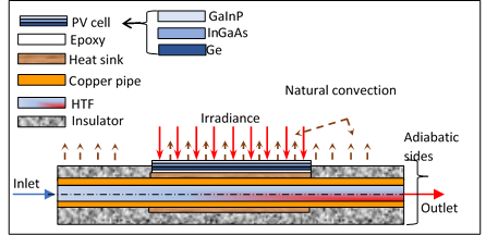
The hybrid CPVT system is comprised of high-efficiency multijunction PV solar cells (MJPV) [6], [7]. The MJPV absorbs a large part of the solar spectrum and is also known as a tandem, consisting of multiple material layers stacked on top of one another using gallium indium phosphide (GaInP), gallium arsenide (GaAs), and germanium (Ge). Each semiconductor utilizes a different wavelength range of the solar spectrum to generate electricity [8]. Over the last 45 years, MJPV has progressed tremendously and achieved higher efficiencies. Compared with the other PV cell technologies, the highest independently certified efficiencies for MJPV solar cells have grown from 29.1% in 2018 to the latest confirmed efficiency record of 47.1% in 2020 [9]. Accordingly, MJPV solar cells have become preferred over single-junction PV cells to be integrated into CPV systems as they have high electrical efficiency, lower temperature coefficients, and better response to highly concentrated solar radiation.
The CPVT is usually categorized into high and low concentrations. The high-concentration CPVT systems are divided into linear-focus and point-focus systems according to their concentration shape [10]. Further, in CPVT systems, the concentration ratio (CR) is a significant parameter, defined as the entrance aperture (area of the concentrator) divided by the exit aperture (area of the receiver). When the CR of the CPVT system increases, the conversion efficiency correspondingly improves. In addition, like other PV/T applications, CPVT is a zero-emission cogenerator system that produces electrical and thermal energy at high overall efficiency and requires fewer solar cells.
The CPVT systems are used for both residential and large-scale applications. A few examples of applications for CPVT systems include water heating [11], water desalination [12], cogeneration of water and electrical power [13], greenhouse heating [14], cogeneration of electricity and cooling [15],[16], desiccant wheel cycle [17], building integration [18], textile industry application [19], and heat recovery with organic Rankine cycle [20]. More details of the recent advancements in commercial applications can be found in this reference [21].
Over the past ten years, there has been a significant increase in research published about the CPVT system. Design considerations and theoretical and experimental investigations have been carried out. These studies' results indicate that hybrid CPVT systems are promising and have unique merits in penetrating the energy market.
The first prototype of CPVT was produced at Sandia National Laboratories. This early work identified most of the problems associated with concentration systems and provided satisfactory solutions to many of them [22]. Kribus et al. [23] studied the thermal and electrical performance of a miniature CPVT module. The results reveal that the overall efficiency was around 80%, whereas the electrical efficiency was about 20%. Mittelman et al. [24] conducted a performance and economic feasibility study with single-effect absorption cooling of a CPVT system. The results demonstrated that integrating power generation plants and solar cooling can be comparable, and sometimes better than the conventional alternative.
Hmouda et al. [25] have designed a new CPVT hybrid system based on a point-focus Fresnel lens and embedded multi-junction photovoltaic cells. Their proposed model was experimentally investigated and numerically modelled under indoor conditions. The results showed that the thermal and electrical performance of the CPVT system improved under testing conditions. The overall efficiency was 68.7% and 73.5% for the experimental and CFD models, respectively. To evaluate the thermal and electrical performance of different configurations of CPV/T systems, Renno and Petito [26] developed a mathematical model for domestic application. They used Fresnel lenses and parabolic mirrors as optical devices. The results revealed that since the fluid output temperature is about 90 °C, using an absorption heat pump with a CPV/T is possible. Ning et al. [27], [28] studied the performance of the HCPV/T system based on a point-focus Fresnel lens with triple-junction solar cells experimentally and numerically. The experimental results showed an electrical efficiency of 28%, a thermal efficiency of 54%, and a total system efficiency of 80%. When they compared numerical and experimental results, they found excellent agreement.
In summary, several researchers have studied the CVPT system. However, a limited number of studies have focused on the CPVT system that uses a point-focus Fresnel lens, MJPV cells, a heat sink, and active cooling. The most critical parts in the manufacture of a CPVT model are widely considered to be the layers between the solar cells and the heat transfer fluid HTF. A significant technical design difficulty for the CPVT system is finding materials for integrating the solar cells that can effectively conduct the heat from the solar cells to HTF while maintaining several critical characteristics, such as high thermal conductivity, low thermal resistance, and high electrical insulation. Moreover, providing good thermal contact between MJPV solar cells and the heat sink under a high concentration ratio while being able to avoid cell cracking from thermal expansion and contraction are significant design considerations in CPVT system development. Consequently, more research, assessment, investigation, and development work related to these design considerations are still necessary.
The objective of this work is to develop a numerical model for the assessment of a CPVT system. The proposed model consists of point-focus Fresnel lens concentrators equipped with high-efficiency GaInP/InGaAs/Ge triple-junction solar cells, copper heat sinks, and an absorber tube as an active cooling system. Further, a more extensive assessment is necessary due to the system's complexity and the fact that various characteristics impact its efficiencies. In addition, since many parameters affect the CPVT system's output, the most important parameters have been selected to study their influence on the proposed model. For this purpose, a three-dimensional CFD model using the Ansys code was developed.
2. Methodology
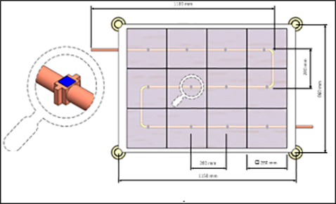
This research aims to evaluate the thermal and electrical performance of a point-focus hybrid concentration photovoltaic thermal CPVT system. A numerical model was developed to study the influence of various operating and design parameters on the overall performance of the CPVT model. Figure 1 shows a schematic diagram of the CPVT model, consisting of 12 point-focus Fresnel lenses, 12 MJPV cells, 12 heat sinks, and a flow loop containing a 1/2-inch copper pipe. The area of the Fresnel lens is 280×280 mm2, and the solar cell size is 10×10 mm2. The heat sinks have been designed to work as adapters to provide a planar surface for MJPV mounting and a round contour on the backside for attachment to the pipe. Epoxy adhesive glue was used to paste the MJPV onto a copper heat sink.
2. 1. Thermal and Electrical Analysis
The performance analysis of the CPVT model is based on an energy balance around the CPVT components. The energy balance includes the incident solar radiation, optical losses from the Fresnel lens, thermal losses from the CPVT, heat flow into the HTF, and electrical energy. Figure 2 shows a side view of the one-dimensional steady-state energy balance and boundary conditions for the CPVT model's longitudinal section of a single cell. There are three heat transfer mechanisms: convection, conduction, and radiation. Some of this heat is transferred within the MJPV solid layers by conduction, with the remaining parts of the heat lost to the surrounding environment by convection and radiation [25].
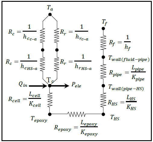
The heat transfer analysis between the CPVT layers can be facilitated by considering the electrical analogy scheme equivalent. Figure 3 presents the thermal resistance diagram corresponding to the CPVT assembly layers. Several assumptions are adopted in this model, including:
- The material properties of MJPV are homogeneous and isotropic.
- The flow is incompressible.
- The thermal properties of the HTF are constant.
- The temperature gradients between cells and their substrates are negligible.
- The radiation was concentrated uniformly along the area of the MJPV cells.
The solar radiation energy received by the MJPV solar cell is partially used to generate electrical energy, and the remains are converted to heat. The simple thermal model assumes a steady state operation. The temperature in the heat sink is uniform due to its high thermal conductivity and adiabatic sides. Applying the first law of thermodynamics, the energy balance equation of the CPVT model is:


Where Qin is the solar radiation flux which reaches the MJPV cell surface in (W), Qheat and Pele are the amounts of energy that are converted to heat and electrical power, respectively in (W), and Qopt is the optical losses of the Fresnel lens in (W). Qth is the thermal energy absorbed by HTF in (W), Qn/c is the natural convection heat transfer rate in (W), Qrad is the surface to ambient radiation energy in (W).
The solar radiation flux can be evaluated from the following relation:

Where qirr is the solar radiation flux in (W/m2), AC is the solar cell area in (m2), and CR is the maximum concentration ratio of the CPVT system and is calculated as follows [29]:

Where AFr is the Fresnel lens area in (m2), and ηopt is the optical efficiency of the concentrator system, and it is typically around 80%−90% [30]. While the following equation can be used to calculate the amount of energy that converts to heat [31]:

Where ηsc is the cell’s electrical efficiency of the MJPV and can be calculated as follows [32]:

Where ηref is the cell's electrical efficiency at the solar cell reference temperature Tref, which is equal to the ambient temperature of 25 °C, Tc is the solar cell temperature, and the β_ref is the temperature coefficient of the MJPV solar cell (%/K) . The values ofηref, βref are usually provided by the manufacturer of the solar cell.
The thermal energy absorbed by HTF is expressed as:

Where ![]() ̇,Cp, Tn and Tout are mass flow rate (Kg/s), specific heat (J/kg.K), inlet, and outlet temperatures of the HTF respectively. The forced convection heat transfer coefficient inside the pipe (W/m2.K) can be calculated as follows:
̇,Cp, Tn and Tout are mass flow rate (Kg/s), specific heat (J/kg.K), inlet, and outlet temperatures of the HTF respectively. The forced convection heat transfer coefficient inside the pipe (W/m2.K) can be calculated as follows:

Where A is the contact area between the inner pipe surface and HTF (m2), Tw is the average wall temperature of the pipe (K), Tm is the average mean temperature of HTF (K). The solar radiation flux that is received by the MJPV cell and converted into electrical power can be determined as follows:

The thermal efficiency can be determined as follows:

The electrical efficiency of the system can be calculated as follows:

The overall efficiency of the CPVT system can be calculated using the following equation:

2. 2. Numerical Analysis
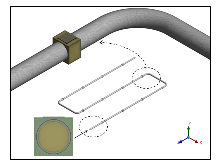
The CPVT system's heat transfer mechanism and thermal performance were investigated using a numerical model, which included heat transfer from the MJPV to the HTF and the total heat losses to the surroundings. The simulation was carried out in Ansys Fluent 19.0 using computational fluid dynamics (CFD). A three-dimensional CPVT model was designed using Ansys Design Modeller. The numerical simulation is performed by applying the Ansys Fluent solver, which uses the Finite Volume Method (FVM) to discretize the governing equations of continuity, momentum, and energy. Furthermore, the energy and laminar flow models are used for this simulation. In addition, a hybrid unstructured tetrahedral and hexahedral mesh was employed in this simulation. The meshing was done using the Ansys Fluent Meshing tool to generate small elements to solve flow and energy equations for the CPVT model computationally. Figure 4 depicts part of the side and isometric views of the meshed CPVT model.
2. 2.1. Mesh independence study
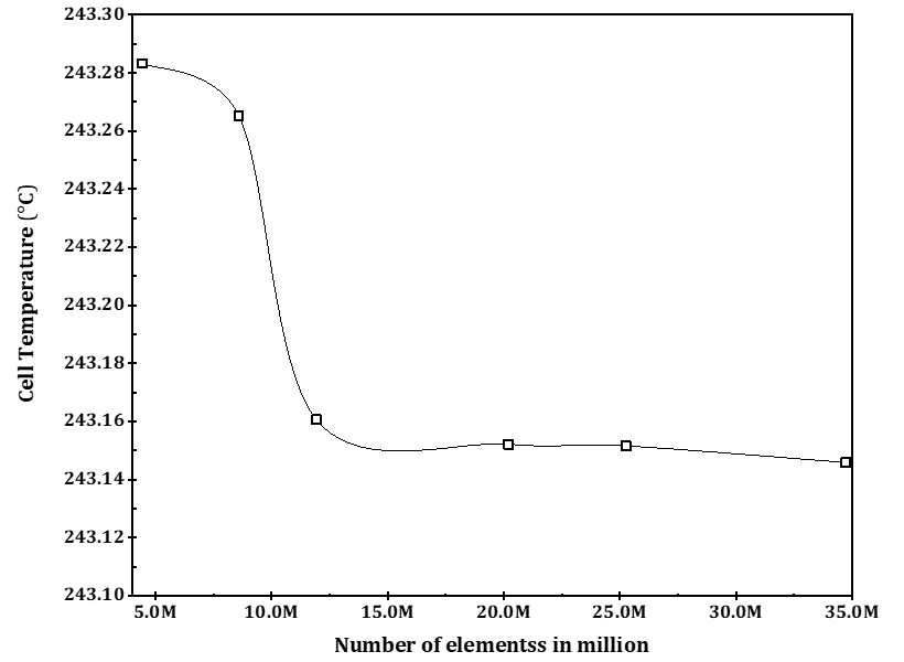
A mesh independence study was conducted, and six mesh independence tests were completed to obtain mesh-independent solutions and sustain credible results. These tests aim to eliminate the influence of discretization, rounding, and iterative errors. The number of mesh elements ranges from 4.0 to 35.0 million, and the study was undertaken in terms of cell temperature. As shown in Figure 5, the results demonstrate that the cell temperature does not vary significantly with further increasing the grid elements. With these results, the number of mesh elements used in this study is sufficient for accuracy and simulation run time.
2. 2.2. Numerical model validation
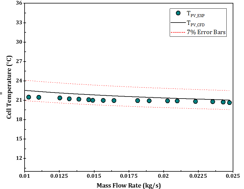
CFD model validation aims to verify the accuracy and reliability of the CPVT model results. The proposed CPVT model was compared with the experimental results conducted by Hmouda et al. [25] at the same number of cells, geometry dimensions, material properties, and operating and boundary conditions. Cell temperature is a significant parameter. Therefore, we chose it as a comparative element. Figure 6 compares cell temperature for both the CFD and the experiment. The maximum error between the experimental and CFD models was about 4.42%. In contrast, the minimum error was 1.54%, confirming that the results are satisfactory and agree well with the experiment results.
3. Results and discussion
This paper assesses the concentrated photovoltaic thermal CPVT system using point-focus Fresnel lens PFFL concentrators. The model consisted of 12 PFFL, 12 MJPV solar cells, 12 copper heat sinks, and a 1/2-inch copper pipe flow loop with a serpentine configuration. The thermal and electrical performance of the CPVT system was investigated at different mass flow rates within the laminar regime flow and at various concentration ratios. It is worth mentioning here that the connections between the points in the graphs are not based on any regression analysis. They have been used to visualize data and display trends and patterns of the variables.
Figure 7 shows the variation in thermal efficiency of the CPVT model against increasing mass flow rate and concentration ratio. As we can see, the thermal efficiency increased as the mass flow rate and concentration ratio increased. The lowest and highest thermal efficiency of the CFD models were 59.5% and 85.3%, respectively. In fact, thermal efficiency increases with two simultaneous effects: (i) An increase in the mass flow rate determines an increase in the amount of thermal energy absorbed by HTF. (ii) An increase in concentration ratio determines an increase in the MJPV temperature, making more heat available for thermal conversion.
Figure 7 shows the variation in thermal efficiency of the CPVT model against increasing mass flow rate and concentration ratio. As we can see, the thermal efficiency increased as the mass flow rate and concentration ratio increased. The lowest and highest thermal efficiency of the CFD models were 59.5% and 85.3%, respectively. In fact, thermal efficiency increases with two simultaneous effects: (i) An increase in the mass flow rate determines an increase in the amount of thermal energy absorbed by HTF. (ii) An increase in concentration ratio determines an increase in the MJPV temperature, making more heat available for thermal conversion.
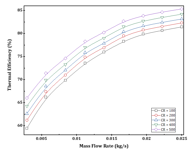
Figure 8 shows the CPVT model's electrical efficiency variation against increasing mass flow rate and concentration ratio. As depicted in the figure, an increase in mass flow rate results in a rise in the electrical efficiency of the CPVT model. This indicates that the increase in mass flow rate allows evacuating a high amount of heat from the MJPV, thereby decreasing the operating solar cells' temperature. Further, an increase in the concentration ratio results in a rise in the temperature of the solar cells. The electrical efficiency is inversely connected to the cell temperature. Consequently, the electrical efficiency is increased as the cell temperature decreases. Moreover, it is observed from Figure 8 that the increase in the concentration ratio results in an elevated cell temperature. Accordingly, the electrical efficiency decreases. In other words, the concentration ratio has an inverse relationship with electrical efficiency. In addition, Figure 8 illustrates that by increasing the HTF flow rate, the electrical efficiency of the CPVT system increases significantly at low HTF flow rates. However, a slight increase in the electrical efficiency appears when the HTF flow rates exceed 0.01 kg/s, especially at low concentration ratios. The highest electrical efficiency occurred at a mass flow rate of 0.025 kg/s, and its value was 35.74%.
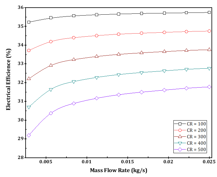
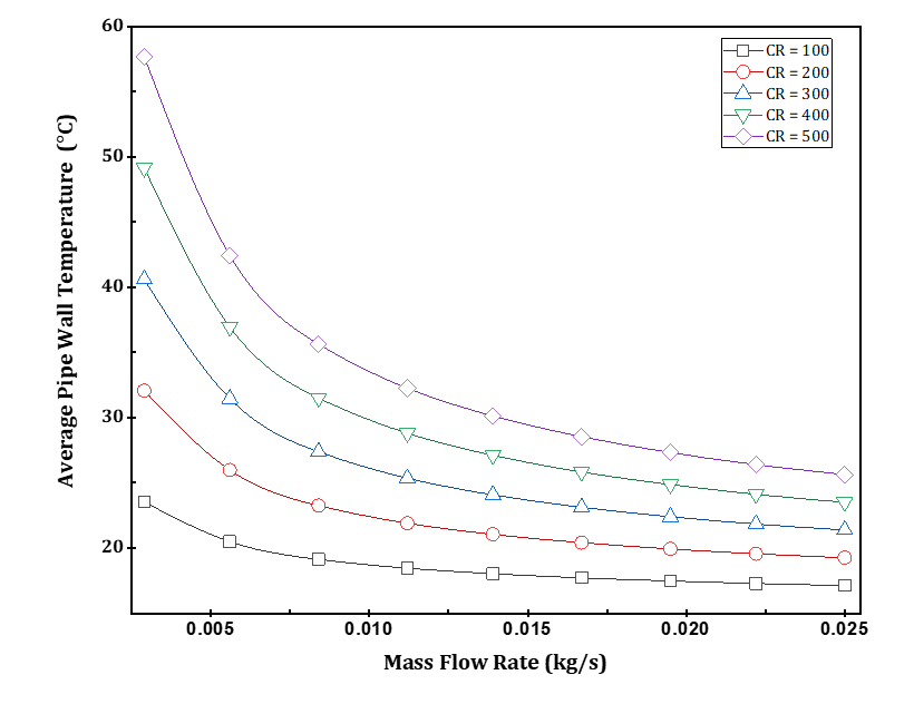
Figure 9 describes the average pipe wall temperature of the CPVT model at different concentration ratios and mass flow rates. As we can see, the average wall temperature decreases significantly with an increased mass flow rate. In addition, the average wall temperature at the lowest concentration ratio (CR = 100x) ranged from 17.13 °C to 23.53 °C. On the other hand, the average wall temperature at the highest concentration (CR = 500x) varied from 25.63 °C to 57.67 °C. These changes are due to the increased heat generated through the MJPV solar cell caused by the increased concentration of solar radiation intensity.
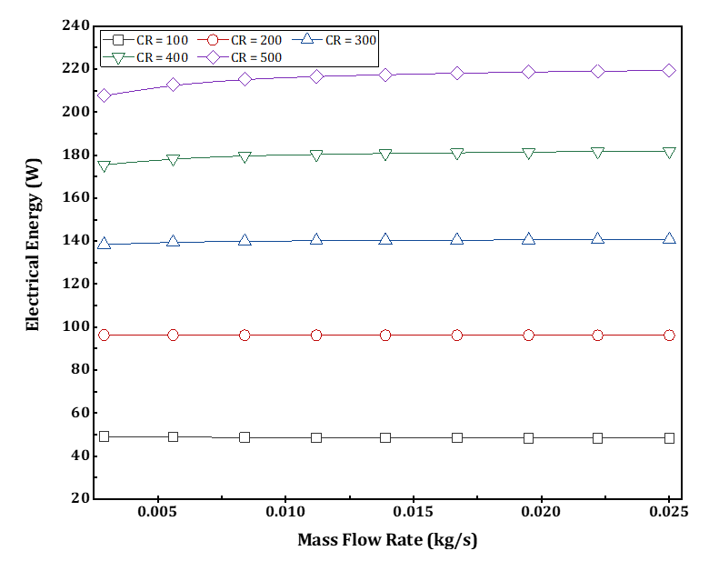
Figures 10 and 11 show the variation of the CPVT model's extracted thermal and electrical energy under different concentration ratios. It is observed that the thermal and electrical power produced is synchronized with the evolution of the mass flow rate and concentration ratios. The maximum thermal and electrical energies were 618.5 W and 219.35 W, respectively. Besides, the highest thermal and electrical energy occurred at a concentration ratio of 500x and a mass flow rate of 0.025 kg/s.
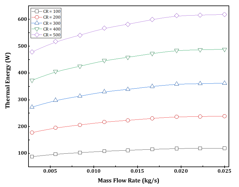
Figure 12 shows the variation of the average cell temperature of the MJPV with the mass flow rate at different concentration ratios. The highest average cell temperature was observed (179 ℃) at a mass flow rate of 0.0029 kg/s and a CR of 500x. The lowest average cell temperature was observed (38.9 ℃) at a mass flow rate of 0.025 kg/s and a CR of 100x. In general, increasing the mass flow rate reduced the average temperature of the MJPV positively. Furthermore, Figure 12 reveals that when the MJPV operates at high concentration ratios, a significant heat load is subjected to the MJPV. Accordingly, they should be cooled to maintain electrical output power at optimum performance in all conditions for a longer life span. As a result, some MJPV solar cell manufacturers have set a recommended operating temperature (ROT) for the MJPV at 110 °C to avoid damage to the solar cell [33],[34].
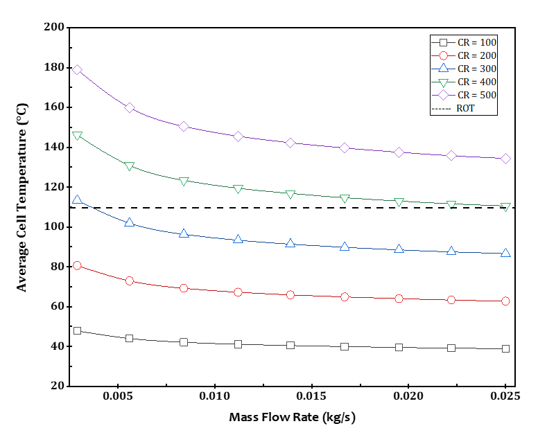
Also, as shown in Figure 12, decreasing the MJPV cell temperature can be achieved by increasing the mass flow rate, but at nearly 0.02 kg/s and above, the MJPV cell temperature does not decrease because the thermal resistances of the CPVT model have reached their maximum limits.
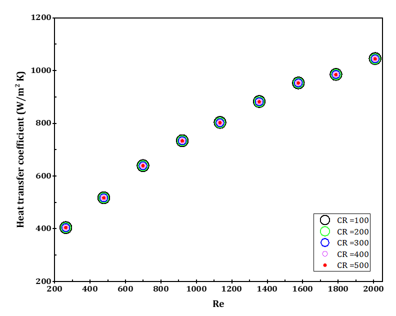
In addition, the heat transfer coefficient has been studied too. Figure 13 illustrates the variation of the heat transfer coefficient of the CPVT model at different Reynolds numbers and concentration ratios. The results demonstrate that the heat transfer coefficient increases with the increase in the Reynolds number, and the variation of the convection heat transfer coefficient up to Re 2000 was between 517 and 1045 W/m2K. In contrast, concentration ratios have no effect on the heat transfer coefficient.
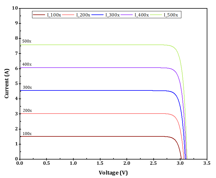
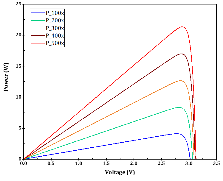
Figures 14 and 15 depict the I-V and P-V curves for a single MJPV cell based on the numerical model at different concentration ratios when the solar cell operates at the same standard measured temperature, i.e., 25 °C. The most common approach to evaluating the electrical characteristics of a CPVT system is to get its response curves, which give short-circuit current Isc, open-circuit voltage Voc, and maximum power output. The changes in Isc and maximum power output with concentration ratios are more significant than in Voc. Nevertheless, both of them increase with the concentration ratios.
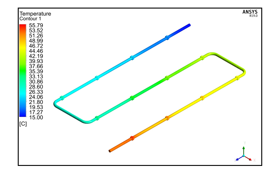
As an example of the whole temperature distribution, Figure 16 depicts the temperature contours of the CPVT model at CR 100x and a mass flow rate of 0.0029 kg/s. As indicated in the figure, that the highest and lowest temperatures for the CPVT model were 55.79 °C and 15.0 °C, respectively.
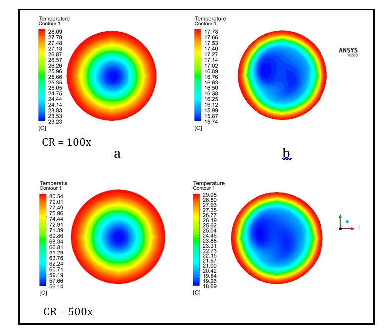
Moreover, Figure 17 displays the temperature contours of the local temperature distribution of the outlet HTF at CR 100x and CR 500x, and HTF flow rates of 0.0029 kg/s and 0.025 kg/s. At CR 100x, the highest and lowest outlet HTF temperatures were 28.09 °C and 15.74 °C, respectively. At CR 500x, the highest and lowest
outlet HTF temperatures were 80.54 °C and 18.69 °C, respectively. The outlet HTF temperature contours observed that the highest temperature distribution occurred near the wall because the flow regime was laminar. Also, we can see that the outlet temperature of the HTF decreases with an increase in HTF flow rates and increases with an increase in the concentration ratio.
4. Conclusion
A 3D numerical model has been developed for assessing the CPVT system using CFD analysis software. The proposed CPVT model is equipped with MJPV solar cells and point-focus Fresnel lenses. The design is simple and reliable and can produce electricity and heat simultaneously. The thermal and electrical performance of the proposed CPVT model was investigated and evaluated under various parameters such as HTF flow rates, HTF inlet temperature, MJPV cell temperature, incident radiation, concentration ratio, and the optical efficiency of the Fresnel lens. A 3D CPVT steady-state heat transfer model was established in the thermal simulation according to concentrated solar radiation on the MJPVs. Based on the predicted results, we found the following:
- The changes in thermal efficiency of the CPVT model against increasing mass flow rate and concentration ratio. The results demonstrate that the thermal efficiency increased as the mass flow rate and concentration ratio increased. The lowest and highest thermal efficiency of the CFD models were 59.5% and 85.3%, respectively.
- The changes in electrical efficiency of the CPVT model against increasing mass flow rate and concentration ratio. The results indicate that an increase in mass flow rate increases the electrical efficiency of the CPVT model. Further, the results revealed that the concentration ratio has an inverse relationship with electrical efficiency. The highest electrical efficiency occurred at a mass flow rate of 0.025 kg/s, CR = 100x, and its value was 35.74%.
- The effect of varying the average pipe wall temperature of the CPVT model at different concentration ratios and HTF flow rates. The average wall temperature decreased significantly with an increased HTF flow rate and decreased CR.
- The effect of varying the CPVT model's extracted thermal and electrical energy under different concentration ratios and HTF flow rates. It is observed that the thermal and electrical power produced is synchronized with the evolution of the mass flow rate and concentration ratios. The maximum thermal and electrical energies were 618.5 W and 219.35 W, respectively.
- The variation of the heat transfer coefficient of the CPVT model at different Reynolds numbers and concentration ratios. The results demonstrate that the heat transfer coefficient increases with the increase in the Reynolds number, and the concentration ratios have no effect on the heat transfer coefficient.
- I-V and P-V characteristics of the MJPV at various concentration ratios with a constant cell temperature of 25 °C. The changes in Isc with concentration ratios are more significant than in Voc. Nevertheless, both of them increase with the concentration ratios.
- The variation of the outlet HTF temperature at different HTF flow rates and concentration ratios. The results show that the HTF's outlet temperature decreases with an increase in HTF flow rates and increases with an increase in the concentration ratio. Furthermore, the highest temperature distribution occurred near the wall because the flow regime was laminar.
Finally, although CPVT technologies are among the most attractive to be developed in renewable energy over the last decades, many challenges still need to be addressed to mature and optimize their functioning.
Acknowledgements
The authors would like to acknowledge the Natural Sciences and Engineering Research Council of Canada for the financial support under grant NSERC 200439, and RGPIN-2021-02504. Also, the author would like to acknowledge the support from the Libyan Ministry of Education.
Conflicts of Interest
The authors declare no conflict of interest.
References
[1] B. D. Elliott, “Evaluation of an indirect solar assisted heat pump water heater in the Canadian environment,” M.A.Sc., Queen’s University (Canada), Canada, 2012. [Online]. Available: http://search.proquest.com/doc-view/1886378591/abstract/D1E9998A7F4D49BCPQ/1
[2] K. Bos and J. Gupta, “Climate change: the risks of stranded fossil fuel assets and resources to the developing world,” Third World Quarterly, vol. 39, no. 3, pp. 436–453, Mar. 2018, doi: 10.1080 /01436597. 2017.1387477. View Article
[3] European Commission, Energy : Roadmap 2050. LU: Publications Office of the European Union, 2012. Accessed: Jun. 30, 2022. [Online]. Available: https://data.europa.eu/doi/10.2833/10759
[4] D. G. für Sonnenenergie, Planning and Installing Solar Thermal Systems: A Guide for Installers, Architects, and Engineers, Second Edition. Earthscan, 2010.
[5] International Energy Agency, “Technology Roadmap - Solar Thermal Electricity 2014 – Analysis,” IEA. https://www.iea.org/reports/technology-roadmap-solar-thermal-electricity-2014 (accessed Jul. 01, 2022).
[6] P. Pérez-Higueras, J. P. Ferrer-Rodríguez, F. Almonacid, and E. F. Fernández, “Efficiency and acceptance angle of High Concentrator Photovoltaic modules: Current status and indoor measurements,” Renewable and Sustainable Energy Reviews, vol. 94, pp. 143–153, Oct. 2018, doi: 10.1016/j.rser.2018.06 .011. View Article
[7] “Triple junction concentrated gaas cell used for CPV system.”https://www.gaas.fullsuns.com/GaAs/GaAs/Triple-junction-concentrated-gaas-cell-used-for-CPV-system.html (accessed Oct. 08, 2020).
[8] Research team, “Experimental and Theoretical Analysis of Microchannel Cooling for Photovoltaic Solar Cells,” National Priority Research Program, Qatar, NPRP No.: 8-956-2-403, Jul. 2014.
[9] “NREL Best Research-Cell Efficiency Chart.” https://www.nrel.gov/pv/cell-efficiency.html (accessed May 19, 2022).
[10] O. Z. Sharaf and M. F. Orhan, “Concentrated photovoltaic thermal (CPVT) solar collector systems: Part II – Implemented systems, performance assessment, and future directions,” Renewable and Sustainable Energy Reviews, vol. 50, pp. 1566–1633, Oct. 2015, doi: 10.1016/j.rser.2014.07.215. View Article
[11] M. Rodrigues Fernandes and L. A. Schaefer, “Long-term environmental impacts of a small-scale spectral filtering concentrated photovoltaic-thermal system,” Energy Conversion and Management, vol. 184, pp. 350–361, Mar. 2019, doi: 10.1016/j.enconman.2019.01. 026. View Article
[12] M. Al-Hrari, İ. Ceylan, K. Nakoa, and A. Ergün, “Concentrated photovoltaic and thermal system application for fresh water production,” Applied Thermal Engineering, vol. 171, p. 115054, May 2020, doi: 10.1016/j.applthermaleng.2020.115054. View Article
[13] Z. Zhang, Z. Hu, and H. Xu, “Theoretical analysis of a solar-powered multi-effect distillation integrated with concentrating photovoltaic/thermal system,” Desalination, vol. 468, p. 114074, Oct. 2019, doi: 10.1016/j.desal.2019.114074. View Article
[14] M. Imtiaz Hussain, A. Ali, and G. H. Lee, “Multi-module concentrated photovoltaic thermal system feasibility for greenhouse heating: Model validation and techno-economic 30, Oct. 2016, doi: 10.1016/j.solener.2016.06.053. View Article
[15] L. Lin, Y. Tian, Y. Luo, C. Chen, and L. Jiang, “A novel solar system integrating concentrating photovoltaic thermal collectors and variable effect absorption chiller for flexible co-generation of electricity and cooling,” Energy Conversion and Management, vol. 206, p. 112506, Feb. 2020, doi: 10.1016/j.enconman.2020. 112506. View Article
[16] A. S. Alsagri, “Photovoltaic and Photovoltaic Thermal Technologies for Refrigeration Purposes: An Overview,” Arab J Sci Eng, Jan. 2022, doi: 10.1007/s13369-021-06534-2. View Article
[17] F. Calise, M. Dentice d’Accadia, C. Roselli, M. Sasso, and F. Tariello, “Desiccant-based AHU interacting with a CPVT collector: Simulation of energy and environmental performance,” Solar Energy, vol. 103, pp. 574–594, May 2014, doi: 10.1016/j.solener.2013 .11.001. View Article
[18] A. Moreno, A. Riverola, and D. Chemisana, “Energetic simulation of a dielectric photovoltaic-thermal concentrator,” Solar Energy, vol. 169, pp. 374–385, Jul. 2018, doi: 10.1016/j.solener.2018.04.037. View Article
[19] W. Ben Youssef, T. Maatallah, C. Menezo, and S. Ben Nasrallah, “Assessment viability of a concentrating photovoltaic/thermal-energy cogeneration system (CPV/T) with storage for a textile industry application,” Solar Energy, vol. 159, pp. 841–851, Jan. 2018, doi: 10.1016/j.solener.2017.11.058. View Article
[20] K. Rahbar, A. Riasi, H. Khatam Bolouri Sangjoeei, and N. Razmjoo, “Heat recovery of nano-fluid based concentrating Photovoltaic Thermal (CPV/T) Collector with Organic Rankine Cycle,” Energy Conversion and Management, vol. 179, pp. 373–396, Jan. 2019, doi: 10.1016/j.enconman.2018.10.066. View Article
[21] J. Jacob et al., “Concentrated Photovoltaic Thermal (CPVT) systems: Recent advancements in clean energy applications, thermal management and storage,” Journal of Energy Storage, vol. 45, p. 103369, Jan. 2022, doi: 10.1016/j.est.2021.103369. View Article
[22] A. L. Luque and A. Viacheslav, Eds., “Past Experiences and New Challenges of PV Concentrators,” in Concentrator Photovoltaics, vol. 130, Berlin, Heidelberg: Springer, 2007, pp. 1–23. doi: 10.1007/978-3-540-68798-6_1. View Article
[23] A. Kribus, D. Kaftori, G. Mittelman, A. Hirshfeld, Y. Flitsanov, and A. Dayan, “A miniature concentrating photovoltaic and thermal system,” Energy Conversion and Management, vol. 47, no. 20, pp. 3582–3590, Dec. 2006, doi: 10.1016/j.enconman.2006.01.013. View Article
[24] G. Mittelman, A. Kribus, and A. Dayan, “Solar cooling with concentrating photovoltaic/thermal (CPVT) systems,” Energy Conversion and Management, vol. 48, no. 9, pp. 2481–2490, Sep. 2007, doi: 10.1016/j.enconman.2007.04.004. View Article
[25] R. A. Hmouda, Y. S. Muzychka, and X. Duan, “Experimental and Theoretical Modelling of Concentrating Photovoltaic Thermal System with Ge-Based Multi-Junction Solar Cells,” Energies, vol. 15, no. 11, Art. no. 11, Jan. 2022, doi: 10.3390/en15114056. View Article
[26] C. Renno and F. Petito, “Design and modeling of a concentrating photovoltaic thermal (CPV/T) system for a domestic application,” Energy and Buildings, vol. 62, pp. 392–402, Jul. 2013, doi: 10.1016/j.enbuild.2013.02 .040. View Article
[27] N. Xu, J. Ji, W. Sun, L. Han, H. Chen, and Z. Jin, “Outdoor performance analysis of a 1090× point-focus Fresnel high concentrator photovoltaic/thermal system with triple-junction solar cells,” Energy Conversion and Management, vol. 100, pp. 191–200, Aug. 2015, doi: 10.1016/j.enconman.2015.04.082. View Article
[28] N. Xu, J. Ji, W. Sun, W. Huang, J. Li, and Z. Jin, “Numerical simulation and experimental validation of a high concentration photovoltaic/thermal module based on point-focus Fresnel lens,” Applied Energy, vol. 168, no. Supplement C, pp. 269–281, Apr. 2016, doi: 10.1016/j.apenergy.2016.01.077. View Article
[29] C. Renno and F. Petito, “Experimental and theoretical model of a concentrating photovoltaic and thermal system,” Energy Conversion and Management, vol. 126, pp. 516–525, Oct. 2016, doi: 10.1016/j.enconman. 2016.08.027. View Article
[30] K. Shanks, S. Senthilarasu, and T. K. Mallick, “Optics for concentrating photovoltaics: Trends, limits and opportunities for materials and design,” Renewable and Sustainable Energy Reviews, vol. 60, pp. 394–407, Jul. 2016, doi: 10.1016/j.rser.2016.01.089. View Article
[31] A. Aldossary, S. Mahmoud, and R. AL-Dadah, “Technical feasibility study of passive and active cooling for concentrator PV in harsh environment,” Applied Thermal Engineering, vol. 100, pp. 490–500, May 2016, doi: 10.1016/j.applthermaleng.2016.02.023. View Article
[32] D. L. Evans and L. W. Florschuetz, “Cost studies on terrestrial photovoltaic power systems with sunlight concentration,” Solar Energy, vol. 19, no. 3, pp. 255–262, 1977. View Article
[33] AZURSPACE, “Enhanced Fresnel Assembly - EFA Type: 3C42A – with 10x10mm2 CPV TJ Solar Cell Application: Concentrating Photovoltaic (CPV) Modules 2014:0–3.” (accessed Aug. 23, 2022). View Article
[34] Spectrolab, “Spectrolab. CDO-030-C3MJ Concentrator Solar Cell. Spectrolab, Inc 2009:2.” (accessed Aug. 23, 2022). View Article