Journal of Fluid Flow, Heat and Mass Transfer (JFFHMT)
ISSN: 2368-6111

Volume 9 - Year 2022 - Pages 121-135
DOI: 10.11159/jffhmt.2022.016
Auxetic Lattice Structures for Turbomachinery Application – a Simulative Parameter Study
Stefan Schröter1, Lukas Reisinger1, Volker Gümmer1
1Chair of Turbomachinery and Flight Propulsion/Technical University of Munich
Boltzmannstraße 15, 85748 Garching, Germany
stefan.schroeter@tum.de; volker.guemmer@tum.de
Abstract - Auxetic structures are characterised by a negative Poisson’s ratio. There are a variety of auxetic structures out of which the relevant ones are highlighted. After a simulative comparison of the thermal and mechanical properties, the most suitable structure and topology is selected for the application in turbomachinery. A parameter variation of this topology leads to an analytical model that describes the mechanical behaviour of the recursive lattice structure as a function of these geometric parameters: the recursive angle 𝛩, the aspect ratio 𝛼, the normalised wall thickness 𝛽, the normalised radius 𝜅 and the cell density 𝑛. Regarding the thermal properties, the so-called resistance length 𝑅L is introduced, which allows a good prediction of the thermal behaviour depending on the cell dimensions. Finally, potential fields of application in the literature are outlined.
Keywords: Auxetic Structures; Turbomachinery; Parameter Study; Intelligent Structures; Structural Mechanics, Material-model, Additive Manufacturing
© Copyright 2022 Authors - This is an Open Access article published under the Creative Commons Attribution License terms Creative Commons Attribution License terms. Unrestricted use, distribution, and reproduction in any medium are permitted, provided the original work is properly cited.
Date Received: 2022-09-09
Date Accepted: 2022-09-18
Date Published: 2022-10-23
1. Introduction
Modern turbomachinery such as aero engines are already sophisticated and efficient machines. In order to find further potential, new methods must be explored. Auxetic structures can lead to further improvement because of their special physical properties. This paper is a basic study on auxetic lattice structures for the use in turbomachinery and gives an outlook on potential applications.
2. Auxetic structures
The Poisson’s ratio ν indicates the ratio of the transverse strain to the longitudinal strain of a material, as shown in equation (1). For most metallic materials, this Poisson’s ratio can be assumed to be ν=0.3. A positive Poisson’s ratio determines that a rod under tensile load decreases its diameter. [1]
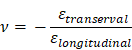
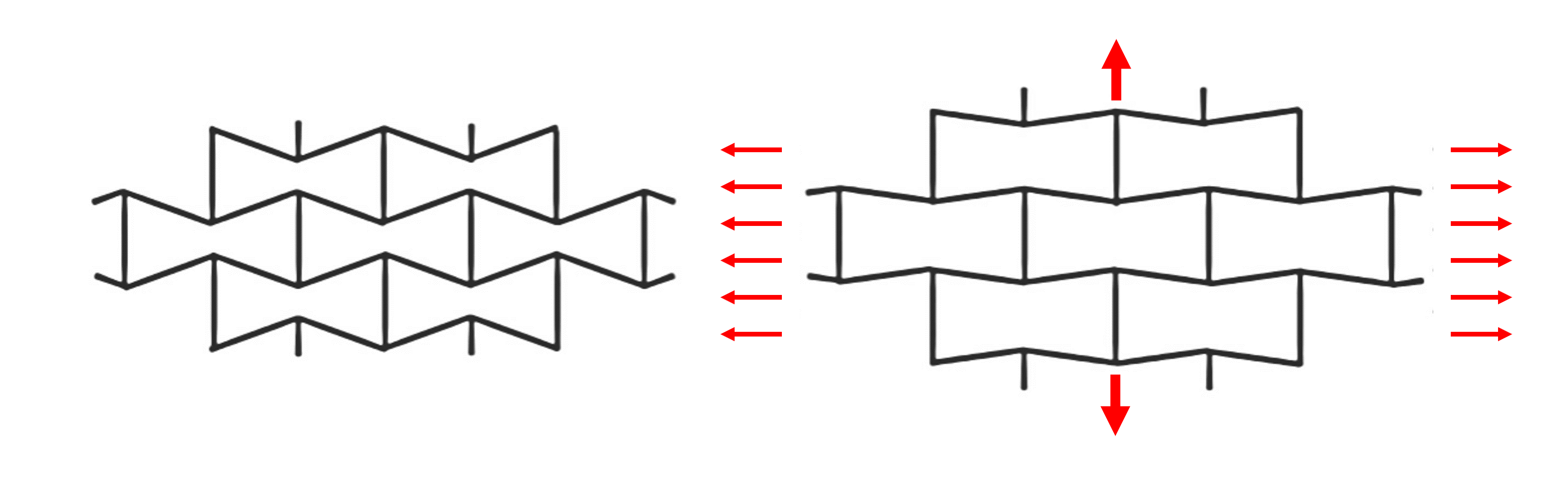
According to Evans [2], transverse contraction behaviour in auxetic structures is counterintuitive. The Poisson’s ratio is negative. Thus, the diameter of a tension rod increases under load. The behaviour of an auxetic material is shown in Figure 1. By loading in the x-direction, the auxetic structure expands in the y-direction or increases its diameter under tension and vice versa for compression. [2]
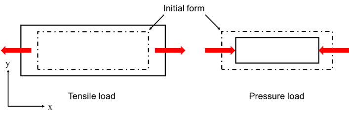
Similarly, auxetic structures contract under pressure. This behaviour is shown in Figure 2 and illustrates why auxetic structures are particularly well suited to prevent intrusion: The auxetic structure increases the density at the point where the ball tries to break through the top layer of the auxetic material. [2]
Furthermore, auxetic structures show a different bending behaviour than conventional structures. For example, Evans [2] describes the shape that auxetic plates assume under bending stress as dome-shaped. This behaviour is also known as synclastic bending behaviour that is shown in Figure 3.

Further differences between auxetic structures and conventional materials can be found in the literature summaries by Liu, Q. [3], Liu, Y. [4] or Yang, W. [5]:
- Increased shear modulus [6]
- Increased penetration resistance [7–9]
- Increased fracture toughness [2]
- Increased energy absorption capacity [8]
3. Overview on auxetic Structures
Several auxetic structures differ in their properties and possible applications. The most important structures are presented below.
3.1 Re-entrant structures
Re-entrant structures denote auxetic cells with inwardly directed walls. The auxetic effect arises from the mechanics within a cell. The material from which the cells are made is often not auxetic. Figure 4 shows the deformation mechanism of a recursive auxetic structure. An expansion in the loading direction and in the orthogonal direction follows an uniaxial tensile load. Figure 4 shows very clearly that the Poisson’s ratio is heavily dependent on the load on the structure. At a specific elongation, the structure looks like a brick wall. From this point on, Poisson's ratio is positive, and the structure no longer shows any auxetic behaviour.
Schwerdtfeger [10] describes a relationship between the relative density and Poisson’s ratio. This means that the structure's stiffness cannot be influenced independently of Poisson's number [10]. A lot of different re-entrant geometries are possible – for example, star- or arrow-shaped cells. Three-dimensional recursive structures are also possible. These can exhibit conventional behaviour in two directions and auxetic behaviour in one direction. The production of such structures is possible through additive manufacturing. [10]
It is also possible to generate auxetic behaviour in three directions (for example, [11, 12] and [13]). Critchley [13] succeeds in producing a three-dimensional auxetic recursive structure in which the local minimum of the Poisson’s number ν=-1.18 can be measured.
3.2 Chiral structures
According to Liu and Hu [4], chiral structures, like recursive structures, are cellular structures. In the case of chiral structures, the auxetic effect arises from the wrapping and unwinding of several struts around a rectangular or round node. When loaded, this node rotates and the distance between the individual nodes increases. In contrast to most other auxetic structures, the chiral structure can permit a significant auxetic effect over a wide range of stresses. The auxetic effect is isotropic, according to Prall and Lakes [14].
Spadoni [15] describes the ratio of the length of the struts "L" to the distance between the node centres "R" as the determining geometry parameter for the auxetic effect. This relationship is shown in Figure 5. For a ratio of L / R = 0.985 the Poisson’s ratio reaches a minimum of ν = -0.94. [15]

3.3 Structures with rotating elements
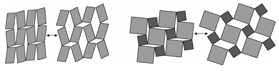
According to Grima and Evans [16], rotating cells can theoretically have a negative Poisson’s number of ν=-1. In this case, the rotating bodies are ideally rigid squares that are interconnected at the corners. In the case mentioned, the structure is isotropic. The auxetic effect arises from the rotation of the bodies and is illustrated in Figure 6. Rectangles, triangles and parallelograms are conceivable as rotating bodies. [16]
3.4 Other structures
Other auxetic structures do not fit into the categories mentioned. However, for the sake of completeness, it should be mentioned: Auxetics also exist at the molecular level [17]. Furthermore, auxetic fibres can also be used in fibre-reinforced composites. Alderson [18] determined the force required to pull fibres out of a matrix. He found that three times more pulling force is required to pull auxetic fibres out of the matrix than for non-auxetic fibres. This can be justified because the auxetic fibre expands and is thus better supported in the matrix.
With the "Keyed Brick" structure, bodies are interlaced so that they also widen in the orthogonal direction under tensile load. This structure can be scaled arbitrarily; it is suitable for immense auxetic structures. Keyed-Brick-structures are isotropic with a Poisson’s ratio of ν=-1 [2]
4. Selecting the right structure for Turbomachinery application
As previously discussed in detail, there are many different types of auxetic structures. Below, an initial selection is made for the use of auxetic structures in engine construction. The aim is to apply the auxetic structures, combining the simplest auxetic structure with the most straightforward application. Therefore, the following criteria are chosen for an initial selection of the auxetic structure:
- Simple structure – the auxetic effect is visually comprehensible
- Material – reliable model creation possible
- No delicate joints – robust against high numbers of cycles
- Implementation with metallic material (additive manufacturing)
- Large auxetic effect perpendicular to the direction of force
Using these criteria and making practical considerations and comprehensive literature research, the auxetic foams, the structures with rotating elements and the fibre composites are excluded. The cellular structures (chiral and re-entrant) are, therefore, most suitable for the aero-engine application. But there is a multitude of these two classes of structures. Therefore, a geometry comparison should generate basic knowledge of auxetic structures' static and transient behaviour under pressure and temperature. Furthermore, the difference between the different geometries can be worked out, and a recommendation on using the structures can be given.
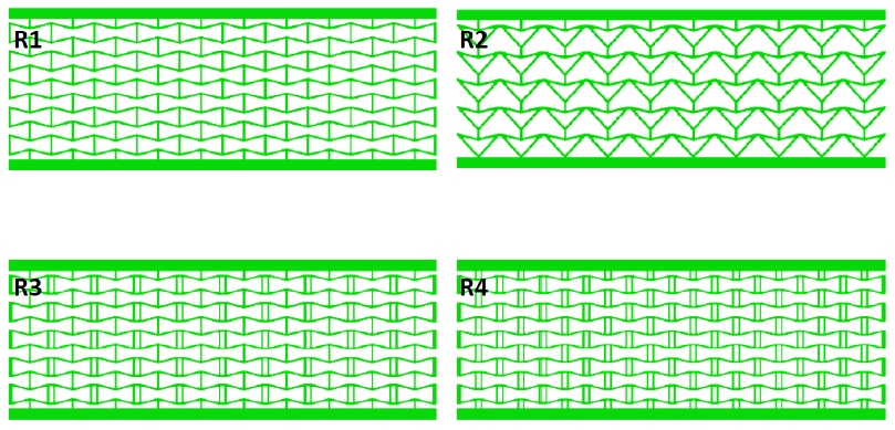
Since Rockel [19] already investigated cellular structures, the two most suitable structures from his work are used. In the following, these structures are referred to as “R1” and “R2” in Figure 7. A topology optimisation by Borovinsec [20] generates cellular structures with a particularly low Poisson's number and thus with a substantial auxetic effect. The design goal of this optimisation is, in addition to minimising the Poisson’s number, a low stiffness from the direction of the force applied to the resulting direction of force. These two parameters are summarised under the term “performance”, and this performance is maximised. Furthermore, the study shows that the auxetic effect of the recursive structure (R1) can be increased by introducing additional cross-connections. Consequently, two more geometries are added to the geometry comparison: “R3,” the structure with the best performance from the topology optimisation and “R4” derived from “R3” with additional connections.
The following cell geometries result for the geometry comparison:
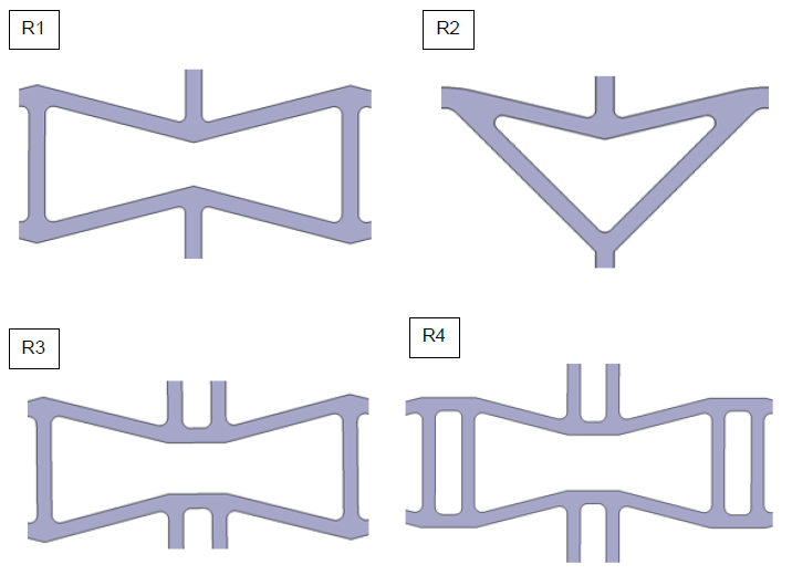
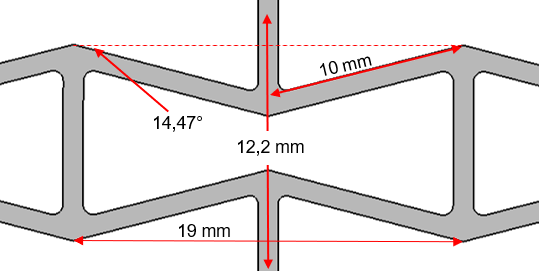
For better comparability, the structures R2, R3 and R4 are generated from the structure R1. Thus, the geometric sizes shown in Figure 8 are valid for all four geometries:
4.1 Design of experiment for the geometry comparison
Considering the loads in aero engines, criteria have been worked out, with whose help the auxetic geometries are compared. These criteria are:
- Auxetic effect
- Behaviour under tensile/compressive load
- Behaviour under shear stress
- Thermal conductivity
- Thermal stresses when the structure is heated
To be able to generate and compare the occurring stresses, the following tests are selected and performed in Abaqus CAE:
- Pressure test
- Shear test
- One-sided heating
4.2 Model setup
Cell grids of the same density and size are generated to compare the geometries. The grids are approximately 200 mm long, 70 mm high, 10 mm thick and weigh 200 g each for the chosen material Ti6Al4V. The variated wall thickness is 1 mm for R1, 1.1 mm forR2, 0.9 mm for R3 and 0.85 mm for R4. These grids are shown in Figure 9.
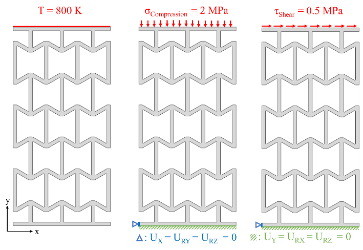
The grids have restrained movement on the lower plate for the pressure and shear setup, and the loads are applied to the top plate. The applied pressure is 20 bar (= 2 MPa), the applied shear stress is 0.5 MPa. For the thermal analysis, the grids top plate has the property 800 K and the rest of the grid 295 K. The schematic model setups can be seen in Figure 10.
The mesh for the shear and pressure test is generated with CPS8 elements. It is a plane stress element with eight nodes. The element size is 0.08 mm for the whole grid except in the corners, where the mesh is refined with the option “curvature control” and the boundary plates, where the element size is 1 mm. Mesh convergence has been proven with a CGI [21] value of 0.001%. The mesh can be seen in Figure 11. For the thermal analysis, the same mesh is used only the element type changes to DC2D8.
Additionally, a non-auxetic reference structure with the same size and density is introduced. The reference structure has ten vertical beams from the top plate to the base plate for the thermal conductivity analysis and expansion investigation. The model setup with boundary plates is not valid for the analysis of thermal stresses because the maximum stress results from expanding the heated plate. Therefore, a grid with five columns, five rows and no boundary plates is “cut out” of the grids shown in Figure 9. The rest of the model setup is just like the setup for the thermal conductivity test.

4.3 Results and discussion
4.3.1 Pressure test:
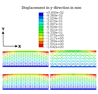
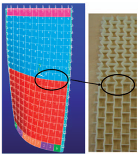
Before going into detail, some general observations can be made: The cells with the lowest load are located at the top and bottom in the middle of the cell grid. The cells, which are in the middle in both the horizontal and vertical directions, show a medium tension level. The cells at the sides are the ones with the highest stress so that an H-distribution of the stress in the cell grids is created. This H-distribution can be observed in all four structures. Looking at the deformation of the cell grid, this H is also reflected in the deformation. The edge cells are strongly deformed. In addition, there is a contraction of the cell grid in the middle (auxetic effect).
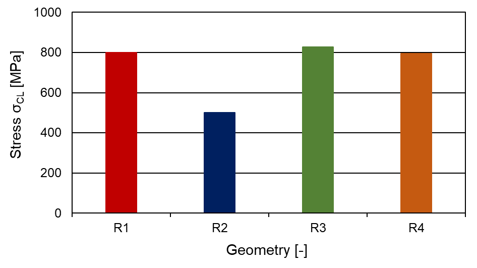
The structures R1, R3 and R4 behave very similarly. There is little difference between these three structures, particularly regarding the maximum stress. Structure R2 is at a significantly lower level in relation to the maximum stress. The maximum stress and compression load σCL for the different configurations is shown in Figure 13.
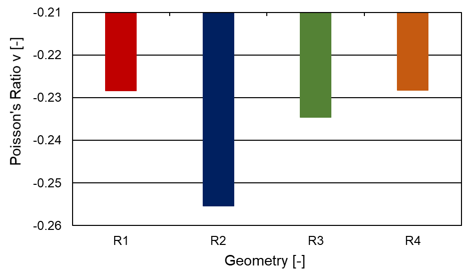
Since the cell grids are all equally heavy and the structure R2 has fewer struts, the struts are designed with a significantly greater wall thickness. As a result, the structure is significantly more robust against the pressure load. This is also reflected in the compression in the X and Y directions. Nevertheless, R2 has a significantly lower Poisson’s ratio than R1, R3 and R4.
The Poisson’s ratios ν for the different geometries are shown in Figure 14.
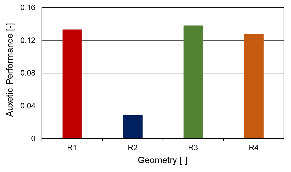
Since it is not the Poisson’s number alone that is of interest for use in engine construction, but a combination of auxetic effect and absolute deformation, the term auxetic performance (shown in Figure 15) is used as the deformation product in the x-direction and Poisson’s ratio. Analogous to the optimisation by Borovinsek [20], the structure R3 shows the greatest auxetic performance, but the difference to R1 and R4 is very small. R2 has an auxetic performance which is considerably lower.
4.3.2 Shear test:
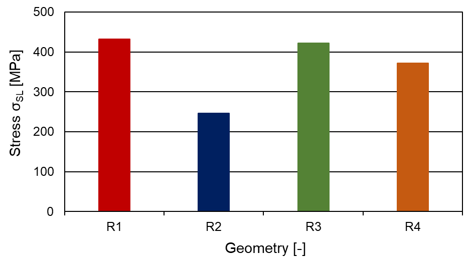
ConfigurationR2 is also the most robust structure in the shear test; this can be attributed to the greater wall thickness. Compared to R4, R3 shows a slightly better robustness against shear. The maximum stress for R4 is approx. 14 % lower than for R1. For R2 there is a 43 % reduction in the peak stress compared to R1. The additional struts in R3 and R4 give the structures more strength under shear stress compared to R1. For the structure R2, the greater wall thickness plays a significant role in the robustness against mechanical loads (see Figure 16).
4.3.3 Thermal conductivity and thermal effects
When the cell grid is heated, thermal stresses arise due to the inhomogeneous expansion of the structure. This inhomogeneity is very strong, especially at the beginning of the heating process, so that the highest thermal stress level occurs here. With increasing time, the expansion of the grid is homogenised, and the thermal stresses decrease. The structure R2 has an exceptionally high stress level. After several minutes, the stress level of structureR2 is twice as high as that of the other three structures. The structures R1, R3 and R4 move at a similar stress level; a slight thermal stress advantage can be observed here at R1. The stretching of the structures in the vertical direction (y-direction) can be used, for example, for targeted changes in the diameter of a body through which the flow passes so that the thermal expansion behaviour is an essential factor in the selection of a recursive structure geometry. In the area under consideration (500 seconds to 5000 seconds), the structure R4 expands the most in the y-direction. The difference to structures R1 and R3 is minimal. The difference toR2 is approximately a factor of 2. The relative expansion in relation to the cell grid is relatively small. Since the cell grids are 60 mm high and the maximum expansion (R4) after 5000 is approx. 0.45 mm.
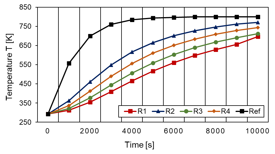
The temperature curves on the lower side of the housing are displayed in Figure 17. The temperature on the bottom of the housing is directly linked to the thermal conductivity since the heat is only supplied to the top of the housing so that a statement can be made about the thermal conductivity or the insulation properties of the different structures. The non-auxetic reference structure shows the highest thermal conductivity. Behind it are the auxetic structures led by R2. The structure with the lowest thermal conductivity or the greatest insulation capacity is R1.
4.4 Selecting the right geometry
The structure R2 is robust against mechanical loads such as shear and pressure due to the higher wall thickness with the same density. In structures R1, R3 and R4, no structure significant appears to have an advantage under pressure load. In terms of shear, the additional struts at R4 show advantages in terms of the maximum occurring stress, eventhough, the level of R2 cannot be reached. The reason for excluding the R2 structure, despite the good mechanical properties, is the poor auxetic performance and the low thermal insulation capacity. In the last-mentioned point, the structure R1 is particularly promising. In addition, R1 is particularly robust against thermal loads. For these reasons, R1 is selected for a parametric study. Since the structures R1, R3 and R4 are similar, the results of this parameter study can also, to a limited extent, be transferred to R3 andR4. For example, in an application with exceptionally high shear stress and little thermal stress, structure R4 should be selected as the basic structure. Structure R1 should be selected for most other applications. R2 can be used in exceptional cases where there is a particularly high-pressure load, and where only a minimal auxetic effect is required.
5. Simulative parameter study on the two dimensional re-entrant auxetic structure R1
In this chapter, the influence of five design parameters on the thermal and mechanical behaviour of the two-dimensional re-entrant auxetic lattice structureR1 is investigated in detail. The simulative parameter study analyses the influence of the recursive angle θ, the aspect ratio α, the normalised wall thickness β, the normalised radius κ and the number of cells n within selected value ranges. Here, the parameters βv and βh are considered differentiated as normalised wall thicknesses of the vertical and the horizontal lattice struts, respectively. The same applies to the separate variation of the number of cells in the horizontal nh and vertical nv spatial directions. The numerical evaluation of the designed recursive structure is carried out with the finite element method (FEM) in Abaqus CAE and forms the core topic of this simulative work. The focus here is on the temperature development over time, the maximum stresses under compressive σCL and shear load σSL, the effective Young’s modulus E and the shear modulus G, as well as the Poisson’s ratio ν. Furthermore, the results of the calculations are compared with the theoretical correlations, according to Gibson [22]. The behaviour under temperature, pressure and shear loads is investigated explicitly in relation to the possible future use of auxetic structures in engine construction.
5.1 Model setup
The basic geometry of the recursive single cell is in principle based on four variable basic design parameters (see Figure 18). These are, according to Gibson [22], the height H of the vertical sidewalls, the length L of the re-entrant horizontal struts, the recursive angle θ and the thickness of the walls t. Furthermore, the radius R and the cell density n of the lattice structure are varied in this paper.

In analogy to Yang [23–25], it is not the absolute values that are primarily of interest but the normalised ratios of the design parameters to each other. In this context, the ratio H/L is defined as the aspect ratio α, the ratio t/L as the normalised wall thickness β and κ = R/L as the dimensionless radius. Together with θ and n they are used as variable design parameters. Due to geometric constraints, not all arbitrary value combinations of θ, α, and β are possible. For the structure used in this work, the geometric constraint results according to equation (2).
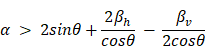
The parameters are varied within the limits, considering the geometric constraint, as shown in Table 1 for the test numbers 1-5.
Table 1. Limits of the varied design parameters for the Test numbers 1-5 from left to right
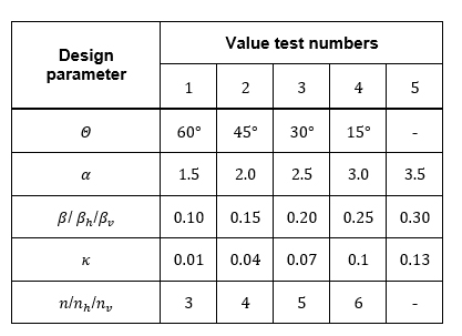
Only one design parameter is varied at a time, while the others are kept constant. The reference grid is a structure with a re-entrant angle of θ=30°, an aspect ratio of α=2.5, a normalised wall thickness of β= βh= βv=0.2, a normalised radius of κ=0.04 and a cell count of n=3 in the horizontal (nh) and vertical directions (nv). This allows a differentiated evaluation of the influence of the individual design parameters on the thermal and mechanical properties compared with the reference structure.
Coupled thermomechanical simulations are conducted with Abaqus CAE to quantify the effect of the parameter variation on an auxetic lattice structure’s thermal and mechanical behaviour. Based on the unit cell as presented in Figure 18, the 2D lattice structure is generated in CAD with CATIA as a parametric model. The thermomechanical boundary conditions implemented are, apart from some slightly different loads levels, analogously to the ones shown in Figure 10 for an exemplary 3x3 reference lattice structure (θ=30°, α=2.5, β=0.2, κ=0.04, n=3). T represents the temperature, σCompression the applied pressure force in negative x-direction (2 MPa) and τshear (0.2 MPa) the shear force in positive y-direction. The implemented fixation of the lattice can also be extracted from Figure 10.
The selected material for the parameter study is the high strength Ti6Al4 titanium alloy. The mesh resolution ensures converged temperature, stress, and displacement results. Particular attention is paid to the densification of the mesh at corners (see Figure 11). Two test series are carried out for each variation of the dimensionless design parameters – except for the normalised radius κ, as here the change of mass due to the change in the normalised radius is negligible. First, all parameters are varied so that the mass m of the lattice structure always remains constant. In the second series of experiments, the parameters are then specified under the condition of a constant lattice height HLattice. This is to prevent the lattice mass or the lattice height from influencing the thermal and mechanical properties to be investigated. If not further specified, all the following results are given for a homogenous lattice temperature of T=293 K for a constant lattice mass m.
5.2 Results and discussion
The primary outcomes and findings are summarised below, and suggestions for practical application are derived, considering the available theoretical and simulative results of this work. All the recommendations are based on the results generated in the parameter variation and must be adapted to the specific application.
5.2.1 Mechanical behaviour
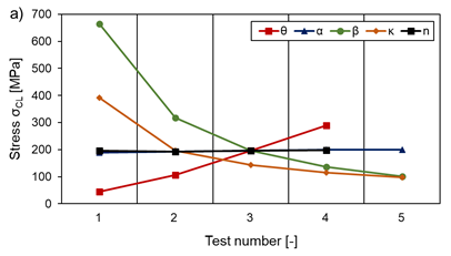
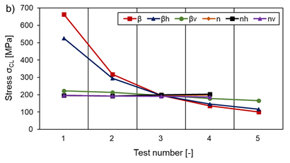
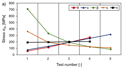
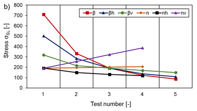
It can be shown that the finite grid size leads to size effects, according to which the deviation of the vertical edge struts falsifies the simulation results, especially the characteristic mechanical properties (E, G, ν). This effect is particularly pronounced for cells with large values for the length of the edge struts H and a simultaneously small wall thickness tv. For this reason, the Poisson’s ratio ν in this study is always determined on an average single cell in the centre of the lattice structure. This ensures reliable and reproducible results. Any deviations from other studies in the literature may be attributed to a different determination of the Poisson’s ratio. The results of the mechanical calculations (E, G, ν, σCL, σSL) are independent of the absolute dimensions of the individual cells or the lattice structure and the mass for all variations investigated, with constant loading. Despite different cell dimensions and masses between the individual test series m=const. and HLattice=const., almost identical results are obtained with the same normalised design parameters. Thus, for the complete characterisation of the investigated lattice structure, only the selected design parameters re-entrant angle θ, aspect ratio α=H/L, normalised wall thickness β=t/L and normalised radius κ=R/L are required. The actual dimensions do not matter if the load remains constant and is not adjusted to the absolute dimensions. Therefore, only the results from the test series with a constant lattice mass m are presented in the following. Modelling to a lattice structure with large angle θ, large normalised wall thickness β (especially for the horizontal struts βh) and a large normalised radius κ, as Figure 19 shows for the test numbers according to Table 1 is recommended to obtain the lowest possible stress level at the inner radii under compressive loading. The stresses converge for the parameters mentioned, which means that increasing or decreasing the design parameters only has a limited effect when a specific value is reached (compare limits in Table 1). The aspect ratio α, together with the normalised wall thickness βvof the vertical struts and the cell density n/nh/nv, only has a small influence on the maximum stress under compressive load compared to the effect of a variation in the other design parameters (see Figure 19 a) and b)).
Similar tendencies can be found for the maximum stresses σSL occurring under shear load, with the exception that these grow almost linearly with increasing aspect ratio α, as Figure 20 shows. Furthermore, a different effect can be observed for the variation of the number of cells in the vertical nv and the horizontal nh direction. While σSL increases with an increased number of cells in the vertical direction, it acts conversely for the cell count in the horizontal direction. The combined increase or decrease of cell density has almost no effect on σSL (see Figure 20 b)). For both load cases (compression and shear), the maximum occurring stress is independent of the lattice temperature and therefore only investigated for T=293 K.
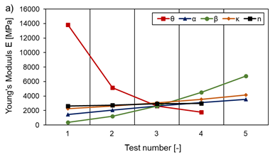
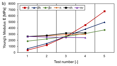
To maximise the Young’s modulus E, cells should be designed with large angles θ, a large aspect ratio α, large normalised wall thickness β (βv and βh), a large cell density (minimal effect) and a tendency towards a larger normalised radius κ, as shown in Figure 21 a) and b). Furthermore, E is found to be constant regardless of the level of the applied compression load for the elastic region.
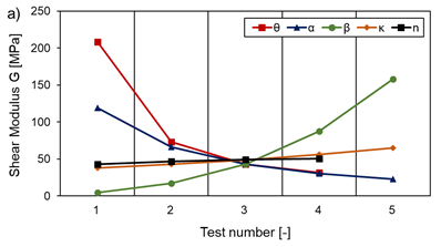
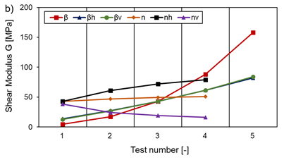
Except for the aspect ratio α, the same tendencies apply to obtaining a large shear modulus G, as Figure 22 illustrates. Here, however, G increases excessively with decreasing α. In addition, when the number of cells alone is varied in the horizontal nh or vertical direction nv, the shear modulus G shows a pronounced size effect (see Figure 22 b)). The variations of βv and βh contribute equally to the increase of the shear modulus G with an increasing normalised wall thickness. In addition, E and G decrease with increasing temperatures analogously to the material properties themselves.
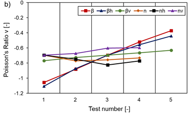
By choosing the angle θ≈45° (compare Table 1), a large aspect ratio α, a small normalised wall thickness β (especially βh) and small normalised radius κ, a minimum Poisson’s ratio ν (independent of temperature and load) is achieved, as Figure 23 illustrates. The cell density n has almost no influence for n ≥ 3 and ν can assumed to be constant. The normalised wall thickness βv of the vertical struts also has a negligible effect on ν, as Figure 23 b) shows. The minimum Poisson’s ratio obtained in this work for the single cell is ν=-1.1 at a stress level of σCL=525.4 MPa for a compressive load. However, a small Poisson’s ratio is not necessarily synonymous with large values for E and G and a high load bearing capacity.

What is particularly important is that parameter changes that reduce the stress level often reduce the auxetic effect at the same time. This means that a heavily loaded structure can only provide a small auxetic effect.
5.2.2 Thermal conductivity
Regarding the thermal conductivity, the so-called resistance length RL is introduced as a meaningful parameter, which allows a good prediction of the thermal behaviour depending on the cell dimensions relative to a reference lattice structure. Here, the minimum distance from the heat source across the unit cell is determined as the decisive factor for the resistance to heating. This is referred to as RL, according to equation (3) and indicates the resistance length in millimetres (mm). Here, nv,ref and Rref are the number of cells in the vertical direction and the radius of a reference grid structure with which the results are compared.

This relationship is derived from geometric dependencies on the unit cell, as shown in Figure 18. The resistance length can be interpreted as the shortest path through a single cell. With the help of the formula, the temporal development of the temperature in the re-entrant lattice structure can be determined in a first approximation compared to a reference structure. The smaller R_L is, the faster the auxetic lattice structure heats up.
The use of a lattice structure with small dimensions H and L, large wall thicknesses tv and th, large angles θ and relatively large radii R to achieve good heat conduction is recommended. The cell density n (also nv and nh) has no influence, when nv,ref is considered for the same dimensions of the lattice itself. The height of the total lattice structure HLattice has only an indirect influence, and results from the variations of the absolute parameters described above in equation (3). The same applies to the design parameters α, β, κ and to the mass m of the lattice. Furthermore, it can be stated that for the given experimental setup, a variable grid height HLattice has a greater influence on the temporal temperature development than a variation in the grid mass m.
5.2.3 Design map
The comparison of the mechanical properties of the lattice structure with the theoretically calculated values according to Gibson [22] shows good agreement in relation to the variation of the aspect ratio α and the normalised wall thickness β for the given simulation setup. Deviations only occur for the Poisson’s ratio ν at large angles θ (θ ≳ 45°). Furthermore, the assumption formulated by Gibson [22] that the variation of the wall thickness of the vertical struts tv has no influence on the Young’s modulus cannot be confirmed. The negligible influence of tv on the Poisson’s ratio, on the other hand, can be confirmed to a certain extent. Comparison with Yang’s simulation results [23–25] shows an excellent qualitative agreement. The dependencies found by Wang [26] also largely coincide with the results of this work, except for the variation of the recursive angle θ. The same deviations as for Gibson [22] can be observed here with regard to the influence of the re-entrant angle θ.
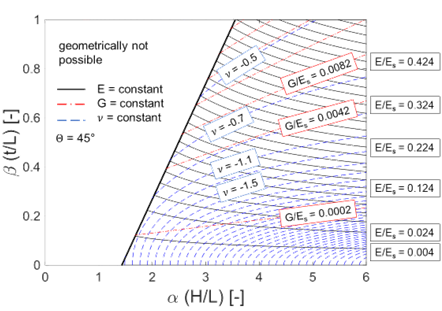
The theoretical correlations derived by Gibson [22] can be used in combination with the results of this work for future approximate design calculations in a first stage of the preliminary design, similar to the approach of Wang [26]. There is good agreement between theory and simulation, especially for small angles θ , which is why the use of a design map according to Figure 24 is suggested as a function of α and β , with constant θ=45°. Plotted over α and β are the lines of constant normalised Young’s modulus E/Es and shear modulus G/Es as well as constant Poisson’s ratio ν, where Es denotes the Young’s modulus of the solid base material. In addition, the geometrically infeasible area according to equation (2) is graphically delimited. The Young’s modulus E and shear modulus G increase from the bottom to the top. The Poisson’s ratio reaches its minimum at the bottom right and increases to the top left. The exact values and the step size can be seen in Figure 24.
6. Possible Applications of Auxetic structures
The literature research shows that some applications of auxetic structures in engine construction have already been investigated. Some aspects of the application examined are presented, and the results are summarised.
6.1 Fan blade with an auxetic internal structure to influence the vibration properties
Lira [27] examines fan blades with different internal structures: In a first step, a fan blade with a honeycomb structure without auxetic properties is compared with a fan blade with an auxetic internal structure. The investigation shows that weight can be saved with the auxetic internal structure on a blade with the same first natural frequency. The higher resonance frequencies are reduced. In a second step, a auxetic gradient structure is created. The angle of the individual cells is varied over the height of the blade so that the auxetic effect is not constant over the height. The auxetic gradient core is shown in Figure 25. [27]
6.2 Auxetic containment
Due to the high energy absorption capacity of auxetic structures, they are particularly suitable for use in fan houses. Webb [28] offers noise reduction, improved containment behaviour and weight reduction as advantages of auxetic fan housings. According to Martin [29], auxetic internal housing structures can be manufactured additively.
6.3 Compressor tip-clearance control
Rockel [19] investigates the passive gap maintenance of the blade tip gap in the high-pressure compressor by using auxetic structures in the compressor housing. As load scenarios, Rockel simulates the cold start of an engine with acceleration to full speed and acceleration and deceleration of the hot engine. His simulations show that the blade tip gap can be reduced using auxetic structures in the compressor housing and thus the compressor efficiency can be increased. The effect is mainly based on the reduced thermal conductivity of the auxetic structure. Martin [29] also lists the transient clearance as an advantage of auxetic housing structures in the patent application for General Electric.
In a follow-up work at the Chair for Turbomachinery and Aircraft Propulsion at the Technical University of Munich Schmidt [30] investigates the active clearance control with auxetic structures in a high-pressure compressor housing. The behaviour of the housing should be actively controlled by changing the internal pressure and the temperature of the auxetic structures. The result of the investigations is that the pressure variation has little effect on expanding the auxetic structure. A temperature variation shows a strong effect. The blowing in of hot and cold air, therefore, leads to the desired expansion behaviour of the housing. [30]
7. Conclusion and outlook
In this paper different auxetic structures for turbomachinery applications are presented. One specific structure (R1) has suitable thermal and mechanical behaviour for the different load conditions that can be found in modern aero engines or stationary gas turbines. A parameter variation on the structure R1 exhibits the relation between the geometry and the thermomechanical behaviour but only for the investigated area. For the investigated area: The re-entrant angle Θ, the normalised wall thickness β and the normalised radius κ should be large for a low stress level. For a large auxetic effect (small Poisson’s ratio), the re-entrant angle Θ must be around 45°, the aspect ratio α should be large and the normalised wall thickness β and the normalised radius κ should be small. The general effect of the cell density nis minimal.
Particularly important is the fact that parameter changes that reduce the stress level often reduce the auxetic effect at the same time. This means that a heavily loaded structure can only provide a small auxetic effect.
Further experimental validation of the numerical study and investigation in terms of fatigue strength and constructional integration is necessary to exploit the advantages of auxetic structures in future engines. Furthermore, a One-Factor-at-a-Time-Analysis as performed in this work is not able to fully display the interrelationships between the factors and the geometry behaviour. A meta-model has to be generated to broadly understand the structure and effects of the different parameters.
References
[1] H.-J. Bargel and G. Schulze, Werkstoffkunde. Berlin, Heidelberg: Springer Berlin Heidelberg, 2012. View Article
[2] K. E. Evans and A. Alderson, “Auxetic Materials: Functional Materials and Structures from Lateral Thinking!,” Advanced Materials, 2000. View Article
[3] Q. Liu, “Literature Review: Materials with Negative Poisson's Ratios and Potential Applications to Aerospace and Defence,” 2006.
[4] Y. Liu and H. Hu, “A review on auxetic structures and polymeric materials: Institute of Textiles and Clothing, The Hong Kong Polytechnic University, Hung Hom, Kowloon, Hong Kong.,” 2010.
[5] Yang W., Li Z.-M., Shi W., Xie B.-H., and Yang M.-B., “Review on auxetic materials,” Journal of Materials Science, no. 39, 2004. View Article
[6] X. Huang and S. Blackburn, “Developing a New Processing Route to Manufacture Honeycomb Ceramics with Negative Poisson's Ratio,” Key Engineering Materials, 206-213, pp. 201–204, 2001. [Online]. Available: 10.4028/www.scientific.net/KEM.206-213.201 View Article
[7] K. L. Alderson, A. Fitzgerald, and K. E. Evans, “The strain dependent indentation resilience of auxetic microporous polyethylene,” J Mater Sci, vol. 35, no. 16, pp. 4039–4047, 2000, doi: 10.1023/A:1004830103411. View Article
[8] R. S. Lakes and K. Elms, “Indentability of Conventional and Negative Poisson's Ratio Foams,” Journal of COMPOSITE MATERIALS, vol. 27, 12 /1993, 1193-1202, 1992. View Article
[9] X. REN, R. Das, P. Tran, T. D. Ngo, and Y.M. Xie, “Auxetic metamaterials and structures: a review,” Smart Mater. Struct., vol. 27, no. 2, p. 23001, 2018, doi: 10.1088/1361-665X/aaa61c. View Article
[10] J. Schwerdtfeger, F. Schury, M. Stingl, F. Wein, R. F. Singer, and C. Körner, “Mechanical characterisation of a periodic auxetic structure produced by SEBM,” Phys. Status Solidi B, vol. 249, no. 7, pp. 1347–1352, 2011, doi: 10.1002/pssb.201084211. View Article
[11] L. Yang, O. Harrysson, H. West, and D. Cormier, “Compressive properties of Ti–6Al–4V auxetic mesh structures made by electron beam melting,” Acta Materialia, vol. 60, no. 8, pp. 3370–3379, 2012, doi: 10.1016/j.actamat.2012.03.015. View Article
[12] M. Proffit and J. Kennedy, “Dynamic response of auxetic structures,” Vibroengineering PROCEDIA, vol. 31, no. 4, pp. 1–6, 2020, doi: 10.21595/vp.2020.21440. View Article
[13] R. Critchley, I. Corni, J. A. Wharton, F. C. Walsh, R. J. K. Wood, and K. R. Stokes, “The Preparation of Auxetic Foams by Three-Dimensional Printing and Their Characteristics,” Adv. Eng. Mater., vol. 31, n/a-n/a, 2013, doi: 10.1002/adem.201300030. View Article
[14] D. Prall and R. S. Lakes, “Properties of a chiral Honeycomb with a Poisson's Ratio of - 1,” Paper, Department of Biomedical Engineering and Department of Mechanical Engineering,, The University of Iowa, Iowa City, 1995. View Article
[15] A. Spadoni, “An Isotropic Auxetic Structural Network With Limited Shear Stiffness,” Denver, Colorado, USA, Nov. 11 2011. View Article
[16] J. N. Grima and K. E. Evans, “Auxetic behavior from rotating squares,” JOURNAL OF MATERIALS SCIENCE LETTERS, vol. 2000, no. 19, pp. 1563–1565. View Article
[17] Chaobin H., Puwei L., Anselm C. G., “Toward Negative Poisson Ratio Polymers through Molecular Design,” Macromolecules, vol. 1998, no. 31, pp. 3145–3147. View Article
[18] K. L. Alderson, V. R. Simkins, V. L. Coenen, P. J. Davies, A. Alderson, and K. E. Evans, “How to make auxetic fibre reinforced composites,” phys. stat. sol. (b), vol. 242, no. 3, pp. 509–518, 2005, doi: 10.1002/pssb.200460371. View Article
[19] D. Rockel, “Zum Potenzial von additiven Fertigungsverfahren in zukünftigen Triebwerksverdichtern,” Dissertation, Lehrstuhl für Flugantriebe, Technische Universität München, München, 2015.
[20] M. Borovinšek, N. Novak, M. Vesenjak, Z. Ren, and M. Ulbin, “Designing 2D auxetic structures using multi-objective topology optimization,” Materials Science and Engineering: A, vol. 795, p. 139914, 2020, doi: 10.1016/j.msea.2020.139914. View Article
[21] Roache, P. J., Ghia, K. N., and White, F. M., “Editorial Policy Statement on the Control of Numerical Accuracy.,” ASME. J. Fluids Eng., March 1986, 1986. View Article
[22] L. J. Gibson and M. F. Ashby, Cellular solids: Structure and properties, 2nd ed. Cambridge: Cambridge University Press, 1997. View Article
[23] D. Yang, S. Lee, and F. Y. Huang, “Geometric effects on micropolar elastic honeycomb structure with negative Poisson’s ratio using the finite element method,” Research Paper, Department of Mechanical Engineering, National Central University, Taiwan, 2003. View Article
[24] L. Yang, O. Harrysson, H. West, and D. Cormier, “Modeling of uniaxial compression in a 3D periodic re-entrant lattice structure,” J Mater Sci, no. 4, pp. 1413–1422, 2013, doi: 10.1007/s10853-012-6892-2. View Article
[25] L. Yang, O. Harrysson, H. West, and D. Cormier, “Mechanical properties of 3D re-entrant honeycomb auxetic structures realized via additive manufacturing,” International Journal of Solids and Structures, pp. 475–490, 2015, doi: 10.1016/j.ijsolstr.2015.05.005. View Article
[26] T. Wang, L. Wang, Z. Ma, and G. M. Hulbert, “Elastic analysis of auxetic cellular structure consisting of re-entrant hexagonal cells using a strain-based expansion homogenization method,” Materials & Design, pp. 284–293, 2018, doi: 10.1016/j.matdes.2018.09.013. View Article
[27] C. Lira, F. Scarpa, and R. Rajasekaran, “A Gradient Cellular Core for Aeroengine Fan Blades Based on Auxetic Configurations,” Journal of Intelligent Material Systems and Structures, vol. 22, no. 9, pp. 907–917, 2011, doi: 10.1177/1045389X11414226. View Article
[28] W. H. Webb, “Fan Case with Auxetic Liner,” US 2015/0345320 A1 D 3 2015, Dec 3, 2015.
[29] A. Martin and A. Sibbach, “Casing with Tunable Lattice Structure,” US2019/0271237 A1, Sep 5, 2019.
[30] T. Schmidt, S. Eisenmann, V. Velikov, and V. Gümmer, “Analysis of an Auxetic Casing Structure for Tip Clearance Control under Various Temperature and Pressure Conditions: ISABE-2017-22629,” 2017.