Journal of Fluid Flow, Heat and Mass Transfer (JFFHMT)
ISSN: 2368-6111

Volume 9 - Year 2022 - Pages 76-84
DOI: 10.11159/jffhmt.2022.010
Magnetohydrodynamic Natural Convection in a Horizontal Concentric Annulus with In-Ga-Sn Alloy and Internal Fins
Aidan Hickie-Bentzen, Syeda Humaira Tasnim, Shohel Mahmud
Advanced Energy Conversion and Control Lab
University of Guelph, School of Engineering
50 Stone Road East, Guelph, Ontario, Canada N1G 2W1
ahickieb@uoguelph.ca; stasnim@uoguelph.ca; smahmud@uoguelph.ca
Abstract - The use of low melting point liquid metals in the thermal management of various systems has seen a recent increase in popularity with the increasing power of commercial CPUs. Natural convection in concentric annuli has also been a popular topic in the literature for decades due to the applications in nanotechnology and energy storage systems. In this study, numerical simulations are performed to investigate magnetohydrodynamic natural convection heat transfer in a horizontal concentric annulus with internal straight, Y-shapes, and T-shaped fins approximated as thin layers. A mix of transient and steady state simulations are conducted using COMSOL Multiphysics® with constant temperature boundary conditions to generate laminar natural convection profiles in the enclosure filled with a eutectic In-Ga-Sn alloy. The average Nusselt number (Nu) at the outer boundary is calculated to compare all simulation results. The Rayleigh number (Ra) is varied to investigate the stability of the flow profile over time, first without fins and then with straight fins. The three fin geometries are then compared at various Ra values to gauge their relative performance, and lastly the magnetic field is implemented at constant Ra for various Hartmann numbers (Ha). The fins are found to increase the stability of the flow profile over time, while the Y-shaped fins increase Nu by up to 318.7% compared to no fins at Ra = 104. The magnetic field forces more even heat dissipation through the enclosure, and at Ha = 20, Nu increases by a further 78.1% for the Y-shaped fins at Ra = 104.
Keywords: In-Ga-Sn alloy; low melting point liquid metal; magnetohydrodynamic natural convection; T-shaped fins; thermal management; Y-shaped fins
© Copyright 2022 Authors - This is an Open Access article published under the Creative Commons Attribution License terms Creative Commons Attribution License terms. Unrestricted use, distribution, and reproduction in any medium are permitted, provided the original work is properly cited.
Date Received: 2022-08-22
Date Accepted: 2022-08-30
Date Published: 2022-09-06
1. Introduction
The use of low melting point liquid metals for convective cooling in thermal management and energy systems has been a topic of interest in the literature for decades but has recently seen a resurgence in popularity with the increased power of modern CPUs [1]. While a variety of metals have been used, Gallium and its’ alloys have become popular due to their favourable thermal properties, chemical stability, and non-toxicity [2]. Liquid metals are also unique compared to conventional cooling fluids, such as air or water, in that they can be influenced by magnetic fields, whether to pump the liquid metal in a convective flow circuit or alter the flow profile of natural convection to enhance heat transfer [3].
Another topic of interest in the literature is natural convection in concentric annular enclosures, with applications in nanotechnology, energy storage and energy conversion [4]. The use of liquid metals in concentric annuli has been explored; Wang et al. [5] investigated magnetohydrodynamic (MHD) natural convection in the annulus and included the effects of optical parameters (radiation). They found that the external magnetic field forced a more even distribution of heat transfer, but they also stated that more work was needed to understand the phenomena. Marocco et al. [6] studied the turbulent mixed convection of liquid metal through the concentric annulus but found challenges in working with low Prandlt (Pr) number fluids, such as liquid metals. The use of extended surfaces (fins) in the annulus has been a popular method of passive heat transfer enhancement. Popular geometries include straight fins, Y-shaped fins, and V-shaped fins [7]. Khan et al. [8] investigated MHD natural convection around a Y-shaped fin, although in a square cavity as opposed to a concentric annulus. They found the fin helped enhance the heat transfer and increasing the Ra and Ha numbers both increased the rate of heat transfer at the fin surface.
This paper investigates MHD natural convection heat transfer in a horizontal concentric annulus and the effects of adding internal straight, Y-shaped, and T-shaped fins using numerical methods in COMSOL Multiphysics®. The liquid metal in the enclosure is eutectic In20.5Ga67Sn12.5 (In-Ga-Sn, In: 20.5%, Ga: 67%, and Sn: 12.5% by mass) [2]. The fins are approximated using a thin layer approximation. Section 2 will discuss the model used, including the geometry, governing equations, boundary conditions, meshes, and physical properties. Section 3 will discuss the results and findings from the study, and section 4 will include brief conclusions and recommendations.
2. Computational Modelling
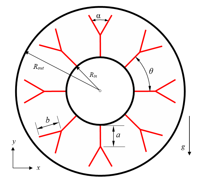
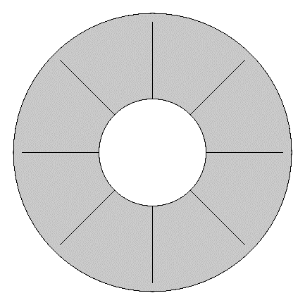
In this study, two-dimensional laminar MHD natural convection is considered. A concentric annular enclosure with a round core tube is studied with a constant aspect ratio (outer radius to inner radius, ϕ) of 2.6 [9]. The fins, attached to the inner surface of the annular enclosure, are straight with one V-branch at the tips of each fin. The geometric parameters are the length of the base fins (a), the length of the V-branches (b), the V-branch angle (α), and the angle between two base fins (θ). The angle θ also dictates the number of fins in the system.
The governing equations to model the flow and thermal fields are given in Eqs. 1 to 4:


Where u and v are the velocity components in the x and y directions, respectively, T is the fluid temperature, P is the pressure, ρ is the density of the fluid, k is the thermal conductivity of the fluid, μ is the dynamic viscosity, Cp is the constant-pressure specific heat capacity of the fluid, g is gravity, β is the thermal expansion coefficient, Tc is the cold-wall temperature, σ is the electrical conductivity of the In-Ga-Sn, and Bx is the magnetic field imposed in the x-direction. The Boussinesq approximation is used to generate the buoyant forces in the momentum equations. The Lorentz force is generated in the positive y-direction in the cases with an external magnetic field. The low magnetic Reynolds number approximation (Rem << 1) is considered, where the flow induced magnetic field is much weaker than the imposed magnetic field and is thus neglected [5]. The Ra is used to define the overall geometry by means of the characteristic length L, given by Eq. 5, where Th is the hot-wall temperature, and Pr is the Prandtl number of the In-Ga-Sn, discussed in section 2.1.
The Ha is determined by Eq. 6 in cases where the external magnetic field is active as a measure of the strength of the magnetic forces versus the viscous forces.
The Nu is calculated at the outer wall to compare simulation results using Eq. 7. A line average of the heat flux q is taken at the outer boundary and used to determine the average outer Nu where k is the thermal conductivity of the In20.5Ga67Sn12.5.
The boundary condition wall temperatures Th and Tc are treated as isothermal, and Th = 310K while Tc = 300K. Initially, the entire enclosure is set to Tc. The tube walls and fins are assumed to act under the no slip condition (velocity is zero at the boundaries). The fins are approximated as thin layers (no conduction resistance). The geometry of the enclosure and fins are scaled relative to the characteristic length L. For example, the total length of the fins is c, which is defined as 90% of L so that the fins never touch the outer wall. The fin base length a and the branch length b are defined as 80% and 20% of c, respectively. Thus, the sum of a and b is c. Note that b is the length of each branch individually but is not counted twice when summing to c. Table 1 lists the parameters used to define both the enclosure size and the fin geometries. Note that the cases where α = 0° produce straight fins, and the cases where α = 180° produce T-shaped fins.
Table 1. Geometric parameters of enclosure and fins
|
Parameter |
Definition |
Description |
|
ϕ |
Rout / Rin = 2.6 |
Aspect ratio |
|
L |
L = Rout - Rin |
Characteristic length, dependent on Ra (Eq. 5) |
|
Rin |
L/(ϕ -1) = Rin |
Inner radius |
|
Rout |
ϕ×Rin = Rout |
Outer radius |
|
a |
c × 0.8 |
Length of fin base (80% of c) |
|
b |
c × 0.2 |
Length of each fin branch (20% of c) |
|
c |
L × 0.9 = a + b |
Total of a and b |
|
α |
α |
Angle between fin branches (V-angle) |
|
θ |
45° |
Angle between fin bases (8 fins) |
The three geometries are provided in Figure 3, showing the straight, Y-shaped, and T-shaped fins given by varying α.
α = 0°
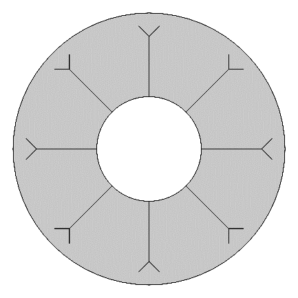
α = 90°
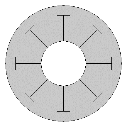
α = 180°
2. 1. Properties of In-Ga-Sn Alloy
The properties of the In-Ga-Sn are documented in the literature. The thermophysical properties are based on recommended equations from Liu and Liu [2], listed in Table 2 along with the electrical conductivity σ of the In-Ga-Sn. Note that the properties are evaluated at 305 K, the average of Th and Tc, and the melting temperature Tm is 283.7 K.
Table 2. Physical properties of In20.5Ga67Sn12.5 [2]
|
Property |
Value |
Description |
|
ρ |
6342.3 kg×m-3 |
Density |
|
Cp |
364.51 J×kg-1×K-1 |
Isobaric heat capacity |
|
k |
24.7 W×m-1×K-1 |
Thermal conductivity |
|
μ |
2.029×10⁻³ Pa×s |
Dynamic viscosity |
|
σ |
3.466×10⁶ S×m-1 |
Electrical conductivity |
The Prandtl number is given by Eq. 8.

This yields a small Pr of 0.030 at 305 K. For low Pr, the flow is typically unstable for Rayleigh-Bénard convection cases where the fluid is heated from the bottom [10]. For Pr << 1, the thermal boundary layer is very large compared to the velocity boundary layer. For the purposes of this paper, the flow is unstable at some values of Ra because the enclosure becomes larger as Ra increases which also increases L, giving more room for Bénard cells to form and leading to oscillations over time.
2. 2. Model Validation
Raithby and Hollands’ [9] developed an analytical model for natural convection in a horizontal concentric annulus, but it is only valid for the range of 0.70 ≤ Pr ≤ 6000. Because Pr = 0.030 for the In-Ga-Sn alloy, the model used for this study is validated by comparison to the experimental work done by Shi et al. [11]. Their enclosure also had an aspect ratio ϕ = 2.6, but the fluid in the enclosure was air (Pr = 0.717). By substituting the properties of In-Ga-Sn with the properties of air into the current model and altering the Ra, the results can be compared directly to their experimental results. The data are listed in Table 3, along with the percent difference.
Table 3. Validation compared to Shi et al. [11]
|
Ra |
[11] Experimental |
Present work |
% Difference vs [11] Experimental |
|
2380 |
1.38 |
1.395 |
1.12 |
|
9500 |
2.01 |
2.083 |
3.64 |
|
32000 |
2.89 |
2.851 |
1.37 |
|
61900 |
3.32 |
3.325 |
0.14 |
|
102000 |
3.66 |
3.727 |
1.84 |
The difference between the present model and the experimental work of Shi et al. [11] is less than 4% at most. Thus, it can be assumed that the present model is reasonably accurate for the In-Ga-Sn alloy cases.
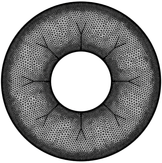
2. 3. Mesh Sensitivity
A mesh sensitivity analysis is performed to determine the relative accuracy of the model based on the number of mesh elements used. COMSOL can automatically build meshes, and the options from “normal” to “extra fine” are compared, with the number of elements plotted against the outer Nu in Figure 4 for each fin geometry. Note that the straight fins generate less elements with the automatic mesh builder for the same sizes, as the small corners of the Y and T-shaped fins have greatly increased local mesh density.
The normal and fine mesh sizes (less than 10000 elements) show some error compared to the finer and extra fine sizes (approximately 20000 elements versus 35000 – 50000 elements, respectively). However, at most there is an approximate 0.5% difference between the finer and extra fine mesh sizes, despite the increased simulation time for the extra fine (as much as from 6 seconds to 17 seconds for a steady state simulation). Thus, the finer size is used throughout this study for the increased speed of simulations and relatively good accuracy.
3. Results and Discussion
3. 1. Stability over time for various Ra
Initially, Ra is swept to observe stability of the In-Ga-Sn flow profile over time in the cases without fins and the cases with straight fins where θ = 45° (8 fins), c = L×0.9 and α = 0°. The model is run as transient for 500 seconds to observe the stability of the convection profile over time by the resulting outer Nu. The results for the case without fins are plotted in Figure 5.
The results for the case with fins are plotted in Figure 6.
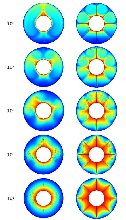
For the cases without fins, the flow profile is very stable at Ra = 104, showing no oscillations once steady state is reached. However, 105 shows small oscillations, and 106 features larger oscillations, although is steady for a period between roughly 150 and 280 seconds. Notably, both 107 and 108 are stable, although take longer to reach steady state than 104. For the cases with straight fins, all values except 108 (which notably performs worse) reach steady state within 500s. This implies that the fins force stability of the flow profile over time, as they reduce the available space for Bénard cells to form in the enclosure. The thermal contours with velocity vectors are shown at 500s for each value of Ra in Figure 7, for both the cases without fins and with straight fins.
3. 2. Effect of fins without external magnetic field
The fins are incorporated as three distinct geometries: straight, Y-shaped, and T-shaped. The parameters θ, a, b, and c are kept constant between fin cases, while α is altered between 0° (straight fins), 90° (Y-shaped), and 180° (T-shaped). The parameters are θ = 45° (8 fins), c = L×0.9, a = c×0.8 and b = c×0.2. The model is run as steady state, as in the range of 104 ≤ Ra ≤ 107, the flow profile is stable over time with fins. The resulting outer Nu for each fin geometry are plotted versus α in Figure 8(a) and versus Ra in Figure 8(b).
For each value of Ra, the Y-shaped fins produce the highest outer Nu. This is likely due to their better thermal penetration depth (i.e., proximity to the outer wall) compared to the T-shaped fins, and better spread compared to the straight fins despite the straight fins having slightly better thermal penetration. All three fin geometries produce higher Nu for each value of Ra compared to the cases without fins, although notably 104 produces higher Nu than both 105 and 106 in the case with Y-shaped fins, and higher than 107 for T-shaped fins, which produces a lower Nu than the case without fins. This implies that the In-Ga-Sn is highly sensitive to the inclusion of internal fins based on geometry and may even perform better if it is left unimpeded by extended surfaces in the enclosure (giving more space to flow) depending on parameters such as Ra and enclosure size.
3. 3. Effect of external magnetic field
Because the fins display similar trends regardless of Ra, a single value of 104 is selected for investigating the effects of the uniform external magnetic field in the negative x-direction, producing the Lorentz force in the positive y-direction opposite to gravity. The results are plotted for the three fins geometries as used in section 3.2 at various values of Ha, shown in Figure 9.
As with the cases without the magnetic field, the Y-shaped fins produce higher Nu than the straight and T-shaped fins. Both the straight and Y-shaped fins benefit more from the influence of the magnetic field than the T-shaped fins. The case without fins begins to benefit from the magnetic field at Ha = 10, while the cases with fins only begin to increase noticeably at Ha = 15. The changes in the flow profile are best shown by streamlines, shown for each case at Ha = 0 and Ha = 20 in Figure 10.
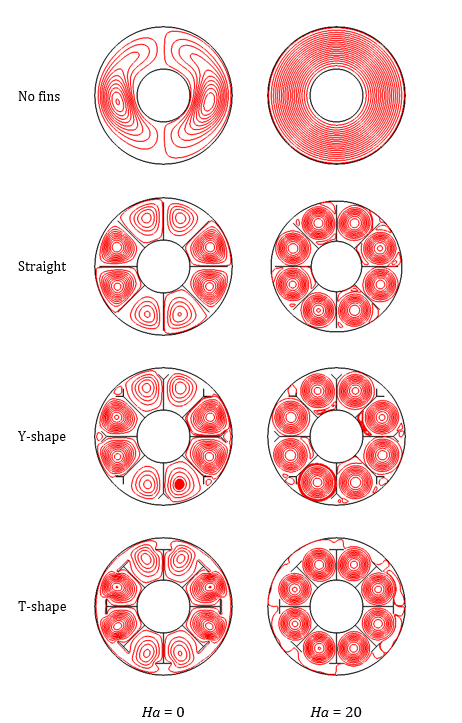
The streamlines show that the magnetic field forces a more uniform flow profile throughout the enclosure. In the case without fins, the streamlines become perfectly circular and even in the enclosure. In the cases with fins, the streamlines become more uniform in the pockets between fins, particularly compared to the bottom and top of the enclosures. The T-shaped fins, however, appear to “trap” the flow between the fins, which explains why they benefit less from the magnetic field than the straight and Y-shaped fins. The resulting outer Nu values for the key cases at Ra = 104 are summarized in Table 3.
Table 4. Outer Nu for various cases at Ra = 104
|
Fin Geometry |
Ha = 0 |
% Increase with fins vs. no fins |
Ha = 20 |
% Increase Ha = 20 vs. Ha = 0 |
|
No fins |
1.07 |
- |
2.38 |
122.4 |
|
Straight |
4.11 |
284.1 |
7.65 |
86.1 |
|
Y-shaped |
4.48 |
318.7 |
7.98 |
78.1 |
|
T-shaped |
3.64 |
240.2 |
5.06 |
39.0 |
4. Conclusion
This study investigated magnetohydrodynamic natural convection of a liquid metal alloy (In-Ga-Sn) in a horizontal concentric annulus. In addition to the cases with no internal fins, three fin geometries (straight, Y-shaped, and T-shaped) were investigated on the internal wall of the enclosure. A uniform external magnetic field was then added to investigate the effects on the convective profile produced by the Lorentz force. Initially, the stability of the flow was observed over time. As Ra increased, the flow become less stable with time due to the low Pr (0.03) of the In-Ga-Sn, but the addition of fins forced stability up to Ra = 108.
In all cases, the fins were shown to increase the outer Nu values, although the Y-shaped fins generally performed the best, increasing Nu by 318.7% at Ra = 104. The addition of the magnetic field increased Nu further by forcing a more even flow profile, and thus better heat dissipation, throughout the enclosure. The straight and Y-shaped fins benefitted more from the magnetic field than the T-shaped fins.
Key findings are summarized as:
- The addition of fins increases stability of the flow profile over time of low Pr fluids in an annular enclosure
- Y-shaped fins increased Nu by 318.7% compared to no fins at Ra = 104 versus 284.7% for straight fins and 240.2% for T-shaped fins
- The magnetic field was most beneficial in the cases with straight and Y-shaped fins, increasing Nu by 86.1% and 78.1% at Ha =20 respectively compared to the cases at Ha = 0, while the T-shaped fins only increased by 39.0%
Acknowledgements
The author is grateful for and acknowledges that the funding for this study was provided through the NSERC grant of Dr. Syeda Tasnim, as well as ERA grant of Dr. Shohel Mahmud, who also provided guidance in performing the research.
Nomenclature
|
a |
Fin base length (m) |
|
Bx |
Magnetic field in x-direction (T) |
|
b |
Fin V-branch length (m) |
|
Cp |
Specific heat capacity (J×kg-1×K-1) |
|
c |
Total fin length (m) |
|
g |
Gravity (m×s-2) |
|
Ha |
Hartmann number |
|
k |
Thermal conductivity (W×m-1×K-1) |
|
L |
Characteristic length (m) |
|
Nu |
Nusselt number |
|
P |
Pressure (Pa) |
|
Pr |
Prandtl number |
|
q |
Heat flux (W×m-2) |
|
R |
Radius (m) |
|
Ra |
Rayleigh number |
|
T |
Temperature (K) |
|
u |
Velocity in x-direction (m×s-1) |
|
v |
Velocity in y-direction (m×s-1) |
|
x |
Cartesian coordinate (m) |
|
y |
Cartesian coordinate (m) |
|
α |
Fin branch angle (°) |
|
β |
Thermal expansion coefficient (K-1) |
|
θ |
Fin spacing angle (°) |
|
µ |
Dynamic viscosity (Pa×s) |
|
ρ |
Density (kg×m-3) |
|
σ |
Electrical conductivity (S×m-1) |
|
ϕ |
Aspect ratio |
Subscripts
|
|
|
|
c |
Cold wall |
|
h |
Hot wall |
|
in |
Inner wall |
|
m |
Melting |
|
out |
Outer wall |
References
[1] Y. Deng, Y. Jiang and J. Liu, "Low-melting-point liquid metal convective heat transfer: A review," Applied Thermal Engineering, vol. 193, 2021. View Article
[2] G. L. Liu and J. Liu, "Convective Cooling of Compact Electronic Devices Via Liquid Metals with Low Melting Points," Journal of Heat Transfer, vol. 143, 2021. View Article
[3] R. Zhao, X. Dou, J. Huang, D. Zhang, D. Xia and X. Zhang, "Mechanisms of energy conversion in induction magnetohydrodynamic pumps for transporting conducting liquids," Energy, vol. 244, 2022. View Article
[4] H. Dawood, H. Mohammed, N. A. C. Sidik, K. Munisamy and M. Wahid, "Forced, natural and mixed-convection heat transfer and fluid flow in annulus: A review," International Communications in Heat and Mass Transfer, vol. 62, pp. 45-57, 2015. View Article
[5] W. Wang, B.-W. Li and Z.-M. Hu, "Influence of Optical Parameters on Magnetohydrodynamic Natural Convection in a Horizontal Cylindrical Annulus," Journal of Heat Transfer, vol. 141, 2019. View Article
[6] L. Marocco, A. A. d. Valmontana and T. Wetzel, "Numerical investigation of turbulent aided mixed convection of liquid metal flow through a concentric annulus," International Journal of Heat and Mass Transfer, vol. 105, pp. 479-494, 2017. View Article
[7] T. Nguyen-Thoi, M. Bhatti, J. A. Ali, S. M. Hamad, M. Sheikholeslami, A. Shafee and R.-u. Haq, "Analysis on the heat storage unit through a Y-shaped fin for solidification of NEPCM," Journal of Molecular Liquids, vol. 292, 2019. View Article
[8] Z. H. Khan, W. A. Khan and M. Hamid, "Non‑Newtonian fuid fow around a Y‑shaped fn embedded in a square cavity," Journal of Thermal Analysis and Calorimetry, vol. 143, pp. 573-585, 2021. View Article
[9] G. Raithby and K. Hollands, "Natural Convection," in Handbook of Heat Transfer, New York, McGraw-Hill, 1998.
[10] H. Liu, Z. Zeng, Z. Qiu and L. Yin, "Linear stability analysis of Rayleigh–Bénard convection for cold water near its density maximum in a cylindrical container," International Journal of Heat and Mass Transfer, vol. 173, 2021. View Article
[11] Y. Shi, T. Zhao and Z. Gup, "Finite difference-based lattice Boltzmann simulation of natural convection heat transfer in a horizontal concentric annulus," Computers and Fluids, vol. 35, pp. 1-15, 2006. View Article