Journal of Fluid Flow, Heat and Mass Transfer (JFFHMT)
ISSN: 2368-6111

Volume 9 - Year 2022 - Pages 66-75
DOI: 10.11159/jffhmt.2022.009
Efficient CFD Methodology for Optimal Design of Oil Cooled Electric Motor Shaft
Rohit Sharma1, Vinay Kumar Gupta1, Alok Khaware1, Vinayak Kamat1
1Ansys Software Pvt Ltd, Research and Development
Plot-34/1 Hinjewadi, Pune, Maharashtra, India, 411057
rohit.sharma@ansys.com; vinaykumar.gupta@ansys.com;
alok.khaware@ansys.com; vinayak.kamat@ansys.com
Abstract - Electric vehicles show a great potential to decrease carbon emissions as compared to traditional internal-combustion engine-based vehicles. An electric motor is one of the most important components of the electric vehicle, which decides the overall performance of the vehicle. A proper cooling mechanism of the electric motor is critical to achieve its optimum performance, safety and reliability. Oil-cooled electric motor designs are frequently utilized in high-power density automotive electric motors. A commonly used electric motor design concept involves a hollow, rotating shaft with holes that supply oil to different motor parts for cooling. Design optimization of rotating shaft is crucial to ensure the required flow distribution for effective cooling. Shaft design optimization involves multiple flow rates, rotational speeds, and geometric parameters. Multiphase flow with length scales varying from a meter to less than a millimetre and high rotation speeds up to 25,000 rpm pose additional challenges in the design analysis and optimization.
Traditionally, experimental methods or flow and thermal network modelling have been utilized for such design optimization studies, but all these methods have their well-known limitations. Therefore, the use of CFD-based design optimization is required for detailed physics-based numerical modelling of realistic geometries. It is crucial to develop an efficient solution methodology for fast and accurate analysis. A steady-state CFD solution methodology is developed to simulate the two-phase flow physics in a rotating shaft using the Volume-of-Fluid method. The solution developed for this application uses the pseudo-transient method and several other numerical recipes to increase the solution accuracy and robustness. The proposed approach is validated against the experimental data for two-phase flow physics in a horizontal rotating shaft with twin exit branches. A benchmarking is also carried out against the traditional full transient approach, and a significant improvement in the turnaround time is observed. A well-integrated and automated workflow is demonstrated for design sensitivity analysis. Overall, the proposed modelling approach allows for a fast, accurate, and robust design analysis, thus making detailed design optimization feasible.
Keywords: Electric Motor, Hollow Rotating Shaft, High Rotational Flow, VOF, Pseudo-Transient, PIDO
© Copyright 2022 Authors - This is an Open Access article published under the Creative Commons Attribution License terms Creative Commons Attribution License terms. Unrestricted use, distribution, and reproduction in any medium are permitted, provided the original work is properly cited.
Date Received: 2022-07-24
Date Accepted: 2022-07-27
Date Published: 2022-08-02
1. Introduction
There has been a remarkable transformation in the engineering landscape due to electrification drive in the automotive, off-highway, and aerospace industries. Air pollution reduction, increasing fossil fuel prices, and government regulations are the key drivers for electrification in the automotive sector. An electric vehicle utilizes an electric traction motor to propel the vehicle in place of a conventional internal combustion engine. Design compaction for increased power to weight ratio of electric motor results in a higher thermal loss density. This poses several engineering challenges, such as optimum lubrication and cooling for better product performance, efficiency, and reliability [1].
An important trend observed is the increase in the rotational speed on an electric motor for improved power to weight ratio. In such designs, oil cooling is more effective than conventional air-cooling methods due to higher loss density. Another important trend is integrating an electric motor with the transmission and other engine components to have a fully integrated powertrain. This requires an oil-based cooling and lubrication strategy within the transmission and electric motor. Conventional splash lubrication systems are not sufficient for the cooling of a high-power density electric motor, and hence direct oil-cooled electric motor architectures are constantly evolving [1].
A commonly used electric motor design concept involves a hollow, rotating shaft with holes for oil cooling, as shown in Fig 1 [1,2].
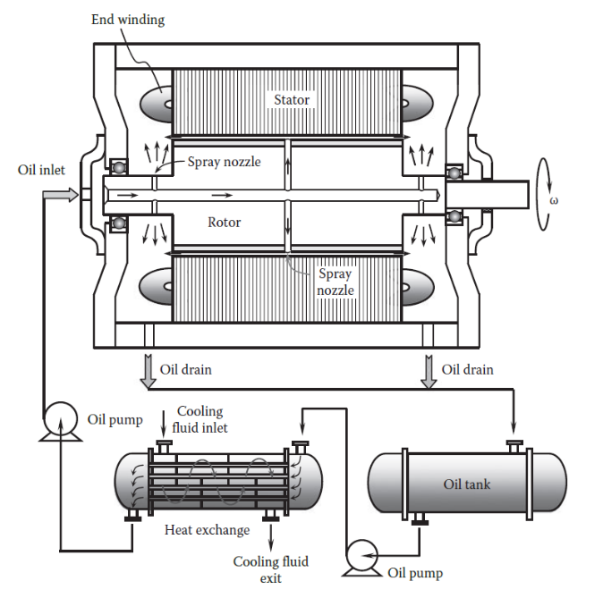
In this design, the cooling oil is pumped into the rotating shaft and discharged from the tiny nozzles. The oil hits the motor end windings to carry away the heat from them. The hot oil is then pumped back into the oil sump, and a heat exchanger then cools it. For optimum electric motor cooling, the hollow rotating shaft's design optimization is crucial to ensure the required flow split-up in front and rear holes. It is a challenging design optimization problem as it involves multiple geometric, flow, and operating parameters. Multiphase flow with length scales varying from a meter to less than one mm, and high rotation speed up to 25,000 rpm further makes the numerical modelling challenging [1].
Modern electrical machine designers require design tools for quick and accurate product development. Adopting simulations in the early design stage can significantly reduce the time to market and the overall cost. Design optimization for proper thermal management is critical for an electric traction motor with heavy-duty cycles and high-power density. Several authors have studied electric motor designs with high rotation speed and having a hollow, rotating shaft for motor cooling [1,3]. Most previous work utilizes experimental or reduced-order modelling approaches such as thermal network and flow-network modelling based on empirical correlations. Any empirical correlation is applicable for a limited set of operating conditions and design types, making it very difficult to be used for detailed design optimization. [1,3]. Experimental methods are costly and time-consuming, and hence they allow a limited design space exploration.
The use of SPH-based approaches may be good for initial design screening. Still, it would not be very accurate for a detailed design optimization as it requires a high fidelity, two-phase flow modelling [4]. While designing electric motors, it is important to resolve secondary leakage flow due to radial clearance in order of 100 microns between stationary and rotating parts. It is a challenge for a traditional SPH-based approach as it requires using tiny particles sizes. The use of minimal particle size increases the total number of particles required in the simulation and increases the computational cost significantly [5]. Therefore, the use of CFD-based design optimization is very desirable. It is a physics-based numerical modelling approach that can accurately model realistic geometries, thermal effects, and temperature-dependent fluid properties. The effects of piping and bends upstream to the rotating shaft and inclusion of leakage effects can be easily included with a detailed CFD-based approach.
This paper focuses on the methodology and workflow development for hollow, rotating shaft design optimization. Having a well-optimized shaft design is the first step towards optimum cooling of the full machine. Therefore, it makes practical sense to focus on the detailed design analysis and optimization of this component. A steady-state CFD solution methodology is developed to simulate the two-phase flow physics in a rotating shaft using the Volume-of-Fluid method using Ansys Fluent CFD software. The solution developed for this application uses the pseudo-transient method and several other numerical recipes to increase the solution accuracy and robustness with aggressive pseudo-time step sizes [6,7]. The proposed modelling approach allows a significantly faster solution than a full transient approach, which makes detailed design optimization practically possible. The case studies in this work are systematically conducted following a step-by-step approach by decomposing the complex problem into sub-problems. This methodology is validated against experimental data and benchmarked against a fully transient approach. Ansys optiSLang is used to orchestrate complete workflow from Ansys Fluent solver to Ansys EnSight postprocessing in an automated manner for conducting the final design sensitivity study. Ansys optiSLang is a process integration and design optimization tool used to conduct variation analysis, design exploration and optimization. [8].
2. Overview of Numerical Methods
2. 1. Governing Equations for VOF Modelling for Rotating Flow
The governing equations for CFD are based on the conservation of mass, momentum, and energy which are solved using the Finite Volume Method (FVM). VOF method is used to capture the interface between the immiscible fluids. If the volume fraction of one fluid in the cell is denoted as α, then α = 0 means that the cell is entirely filled with primary fluid; α = 1 means that the cell is entirely filled with secondary fluid and 0< α<1 means that the cell is partially filled and contains the interface. Summation of volume fraction for all the fluids should be equal to one.
The volume fraction equation in the absence of mass sources is given as:
The continuity equations can be written as:
For VOF model, a single momentum equation is solved throughout the domain and the resulting velocity field is shared among the phases. Momentum equation using absolute formulation for rotating frame of reference is represented as:

Momentum equation in the absolute formulation for moving mesh approach is represented as:

Where ![]()
![]() is the relative velocity viewed from the moving frame and
is the relative velocity viewed from the moving frame and ![]() is the velocity of the moving frame relative to the inertial reference frame.
is the velocity of the moving frame relative to the inertial reference frame. ![]() and
and ![]() are the angular and absolute velocity, respectively.
are the angular and absolute velocity, respectively.
![]() ,
, ![]() ,
, ![]() ,
, ![]() ,
, ![]() are represented as density, pressure, stress tensor, body force and time, respectively. The properties in the continuity and momentum equations are volume weighted averaged properties.
are represented as density, pressure, stress tensor, body force and time, respectively. The properties in the continuity and momentum equations are volume weighted averaged properties.
2. 2. Pseudo-Transient Method
The pseudo-transient method is a time marching technique to achieve a steady state solution in a robust manner using the pseudo time step size. Robustness of steady-state calculations is improved due to added diagonal dominance from pseudo-transient terms. It also serves the purpose of providing local implicit under-relaxation.

Where, ρ is the density, ΔV is the cell volume, ϕp and ϕnb are the solution variables at the cell-center and neighboring cells, ap and anb are coefficients of central and neighboring cells, ∆τ is the pseudo time step size and b is the source term.
This method can be assisted with stabilization techniques such as dual pseudo-time stepping, and smoothing methods to improve the solution stability with aggressive pseudo-time step size.
2. 3. Pressure-Velocity Coupling
The pressure based coupled approach solves the momentum and continuity equations together and thus provides a robust and superior performance compared to the segregated approach. The full implicit coupling is achieved through an implicit discretization of pressure gradient terms in the momentum equations, and an implicit discretization of the face mass flux, including the Rhie-Chow pressure dissipation terms [6].
2. 4. Compressive Scheme for Volume Fraction Discretization
The compressive scheme is a second order scheme based on slope limiters [6].
Where, ![]() , <
, <![]() ,
, ![]() are the face volume fraction, donor cell volume fraction and the slope limier having a maximum value of 2.
are the face volume fraction, donor cell volume fraction and the slope limier having a maximum value of 2. ![]() is the donor cell volume fraction gradient cell and
is the donor cell volume fraction gradient cell and ![]() is the position vector between donor cell centroid and face centroid [6].
is the position vector between donor cell centroid and face centroid [6].
3. Solution Methodology
The complex physics of two-phase flow in a rotating shaft is resolved using several fundamental case studies following a step-by-step approach. The proposed solution methodology is validated against experimental data published on two-phase flow physics in a rotating tube with twin exits [9]. After that, the validated solution approach is applied in a full 3D design similar to a real-life electric motor shaft design to conduct a design sensitivity study. Ansys optiSLang is used to orchestrate complete workflow from Ansys Fluent solver to Ansys Ensight postprocessing in an automated manner. In a real-life electric motor, the oil flow rate and motor rotation speed vary based on the system operating conditions. The study provides the sensitivity of a given design to the operating conditions like inlet oil flow rate or rotation speed for a given geometry.
The pressure-based coupled solver is used along with the pseudo-transient method with an automatic pseudo-time step size. The Compressive scheme is used for the volume fraction discretization using an Implicit steady-state VOF formulation. [6]. PRESTO! (PREssure STaggering Option) is used for the face pressure interpolation whereas, 2nd order upwind discretization schemes are used for the momentum and other transport equations [6]. Single reference frame, absolute velocity formulation is used to model the rotational effects. Following two initialization tricks are used to reduce the computational time needed to reach the final steady-state solution. Firstly, the shaft is initialized with a rotational velocity field. Secondly, the shaft is filled with oil as filling time can be significantly long in shaft designs with large internal cavity volumes. High-order term relaxation is used to provide solution stability [6]. Mass flow inlet boundary condition is used for inlet, and pressure outlet boundary condition open to the atmosphere is used for all outlets. Backflow direction from neighbouring cells is used to handle reverse airflow at pressure outlet boundaries in a physically correct manner. All case studies presented in this paper assume isothermal conditions as the focus is on the rotational, two-phase flow physics resolution.
3. 1. Solution Methodology Development using Fundamental Case Studies:
This case study aims to develop and present a steady-state VOF based solution methodology for design analysis of a hollow rotating shaft’s two-phase flow behaviour and the flow split-up, crucial for optimum cooling. In a real-life electric motor, the oil flow rate and motor rotation speed vary based on the system operating conditions. All the operating conditions and fluid properties are captured in Table 1 and Table 2, respectively. A systematic step-by-step analysis approach is used to develop the best practices for numerical modelling.
Table 1: Operating conditions
|
Inlet Oil Mass Flow Rate (kg/sec) |
Minimum |
Maximum |
|
0.02 |
0.1 |
|
|
Shaft Rotation Speed (rpm) |
Minimum |
Maximum |
|
1000 |
15000 |
Table 2: Fluid properties
|
Material Properties |
Value used |
|
Oil Density (kg/m3) |
895 |
|
Oil Dynamic Viscosity (kg/m-sec) |
0.0043 |
|
Air Density (kg/m3) |
1.225 |
|
Air Dynamic Viscosity (kg/m-sec) |
1.78e-05 |
The effect of air-density, initialization approach, pseudo-transient vs full transient, rotating reference frame vs sliding mesh, gravity, surface tension, and turbulence modelling are evaluated. Two lightweight sample cases are created to study these flow and numerical modelling aspects.
Case Study 1: 2D Axisymmetric Modelling of a Rotating Shaft
In this case study, a 2D domain is used with a quad-structured grid of 44.5k elements. Simplification is done using a 2D axisymmetric swirl representation of the actual geometry as it captures the full physics with less computational efforts. A uniform mesh size of 0.1mm is arrived at after conducting a grid dependence study. The model dimensions are shown in Fig 2. The operating conditions and fluid properties are taken from Table 1 and Table 2.

Case Study 2: Full 3D Modelling of a Rotating Shaft
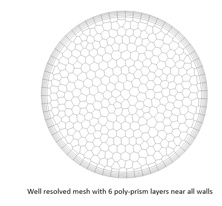
In this case study, a 3D domain is used with a polyhedral mesh of 3.2M elements, as shown in Fig 3. A uniform mesh size of 0.1mm is arrived at after conducting a grid dependence study. The operating conditions and fluid properties are taken from Table 1 and Table 2.
3. 1.1. Detailed Investigation of Flow and Modelling Aspects
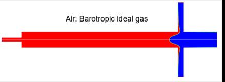
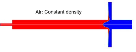
- Effect of Air Density Modelling:
Air density modelling can be important as the air gets entrained in the rotating tube. Case 1 2D model is used to compare the effect of constant air density versus barotropic ideal gas modelling. As shown in Fig 4, an almost identical final steady-state solution is found irrespective of the density modelling method as the flow speeds are well below the 0.3 Mach limit. Similar studies are conducted on multiple design points. Therefore, constant air properties are used in the final simulation methodology while performing isothermal modelling.
- Effect of Initialization:
The effect of initialization is studied using the Case 1 2D model. Initialization can be important to reduce the time needed to fill a shaft if the shaft has a significant amount of oil stored in the final steady state. As shown in Fig 5, an almost identical final steady-state solution is found irrespective of the initialization.
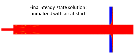
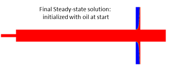
For an operating point with less air entrainment, initialization with fully oil filled shaft is found to accelerate the solution significantly.
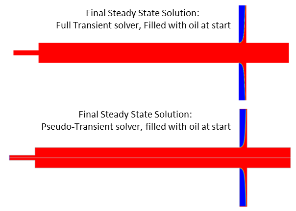
- Effect of Pseudo-Transient versus Full Transient Approach:
The effect of pseudo-transient modelling versus full transient modelling is studied using the Case 1 2D model with a rotating frame of reference. As shown in Fig 6, an almost identical final steady-state solution is found irrespective of the solution approach. Similar studies are conducted on multiple design points. The pseudo-transient approach is found very useful to reduce the simulation time by 10-20 times. Therefore, a pseudo-transient steady-state VOF solver is used in the final solution methodology.
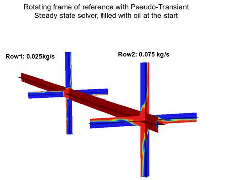
- Effect of Pseudo-Transient with Rotating Frame of Reference versus Full Transient Approach with Sliding Mesh Model:
The effect of pseudo-transient modelling with a rotating versus full transient modelling with sliding mesh model is studied using the Case 2 3D model. As shown in Fig 7, an almost identical final steady-state solution is found irrespective of the solution approach. solution methodology.
Similar studies are conducted on multiple design points. The pseudo-transient approach is found very useful to reduce the simulation time by almost one to two orders. Therefore, a pseudo-transient steady-state VOF solver and a rotating frame of reference are used in the final solution methodology.
- Effect of Gravity Modeling:
Gravity effects are insignificant at high rotation speeds as the centrifugal acceleration is much larger than the acceleration due to gravity.
- Effect of Surface Tension Modeling:
Surface tension effects are insignificant as the flow has high inertia and a high Weber number.
- Effect of Turbulence Modeling:
Two-equation, SST K-Omega turbulence model with curvature correction, is utilized to capture turbulence and swirl effects as a rotating shaft have forced vortex flow [6]. Results obtained by using this turbulence model are compared against the higher fidelity Reynolds Stress model for verification.
3. 2. Validation Case Study using the Proposed Solution Methodology
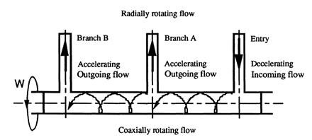
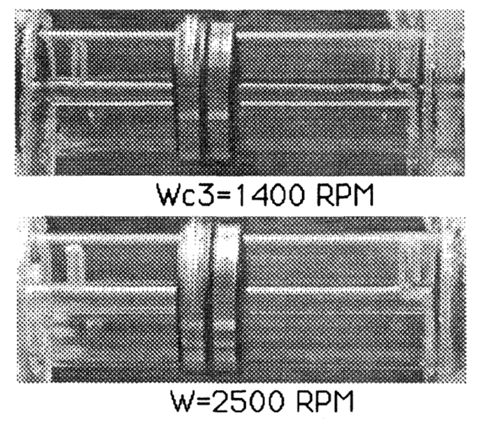
The objective of this case study is to validate the above-proposed solution methodology against experimental data published by Sun-Wen Cheng et al. for a two-phase flow in a hollow, rotating shaft problem with twin exits [9]. The flow regime, the shape of the film developed in the inner walls of the shaft and the flow split up between the twin exits are compared between experiments and CFD. At rotation speeds in the range of 1400-2500 rpm, a steady, annular flow regime is observed experimentally [9]. A rotation speed of 2000 rpm and an inlet mass flow rate of 0.3 GPM (1135.6 cc/min) is selected for validation as it is close to an operating point for a typical 25-40 kW electric motor shaft.
The schematic model of the experimental shaft and steady, annular flow regime is observed in the range of 1400 rpm to 2500 rpm, as shown in Fig 8 and Fig 9 respectively [9]. The inlet and outlet branches of 25.4 mm length are connected with a rotating pipe of 469.9 mm length and 12.7 mm inner diameter (ID). The inlet branch and branch A have an ID of 6.35 mm, and branch B has an ID of 3.175 mm. The oil used in the experiments has a density of 815 kg/sec and kinematic viscosity of 12.99 mm2/sec corresponding to the temperature of 32 Deg C. Air has a density of 1.225 kg/sec and a molecular viscosity of 1.78e-05 kg/m-sec. The solution methodology proposed in section 3.1 is used for this analysis. As the final steady-state condition has significant air entrainment, the shaft is initialized with air to reduce computational time.
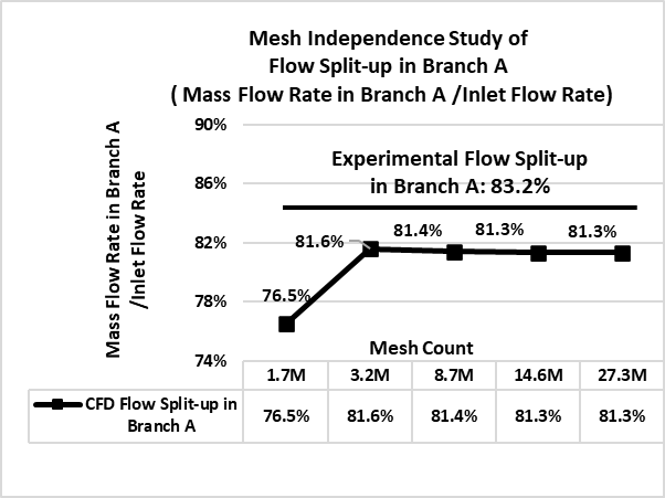
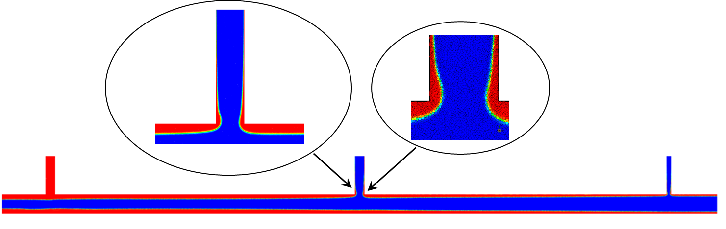
Experimentally 85.6% of inlet flow is going towards branch A, and around 14.4% flow is going towards branch B at 2000 rpm [9]. Experimental flow split up of 83.2% in branch A is used to compare with CFD results considering +/- 2.4% uncertainty in experiments [9]. Mesh dependency study was performed on 5 grids with polyhedral element count of 1.7M, 3.2M, 8.4M, 14.7M, and 27.3M. It is found that the case with 14.7M elements give a mesh independent flow split up and resolves all the necessary flow structures. CFD reported values were found to be in a close agreement with the experimental data. As per CFD analysis, 81.3% of inlet flow is going towards branch A, and 18.7% flow is going towards branch B as shown in Fig 10. The annular flow regime and film shape predicted by CFD are shown in Fig 11 and results are in a close agreement with experiment (less than 5% difference), as shown in Fig 9.
3. 3. Detailed Design Sensitivity Study of a 3D Rotating Shaft
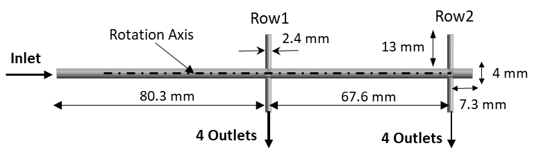
The objective of this case study is to apply the above-proposed solution methodology for design sensitivity analysis. The model dimensions for this case are shown in Fig 12.
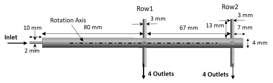
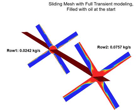
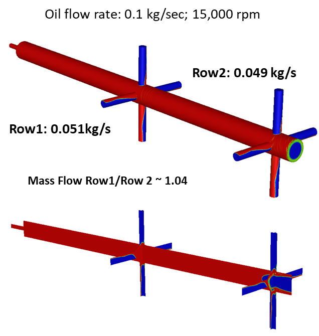
The oil-air flow distribution and the flow split between row 1 holes and row 2 holes are the key simulation outputs. A mesh with 8.5M of polyhedral elements is used in this case study. A uniform mesh size of 0.1mm is arrived at after conducting a basic grid dependence study. The operating conditions and fluid properties are taken from Table 1 and Table 2. Analyses are conducted for two flow rates of 0.04 kg/s & 0.1 kg/s and three rotation speeds of 1000 rpm, 5000 rpm, and 15000 rpm to cover the entire design space.
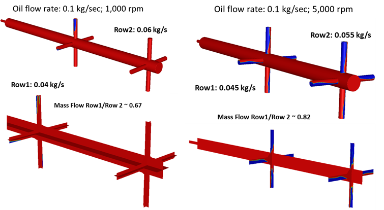
The entire design space is simulated successfully with the proposed pseudo-transient methodology, as shown in Fig 13.
At higher rotation speeds, the outlet oil jet becomes thinner due to larger centrifugal accelerations. Air entrainment is found to be more at higher rotation speeds due to higher suction pressure. As the flow rate increases, the air core becomes smaller as the tube is filled with more oil due to inertial effects.
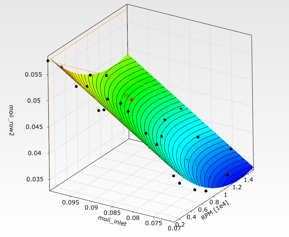
Ansys optiSLang based workflow is used to explore the design's sensitivity to operating conditions like inlet oil flow rate (0.07 to 0.1 kg/sec) and rotation speed (2000 to 15,000 rpm). The complete process from CFD solver to postprocessing is orchestrated in an automated way, as shown in Fig 14.
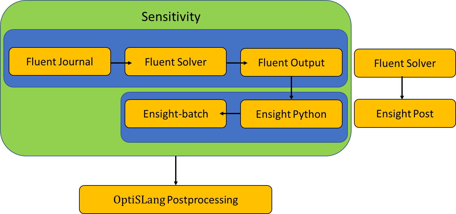
The robust and fast steady-state VOF modelling approach allowed performing simulations for ten design points on 160 cores (Intel Xeon Gold 6142, 2.6 GHz) in a total of 10 hours for an industrial mesh size of 8.5 million polyhedral elements.
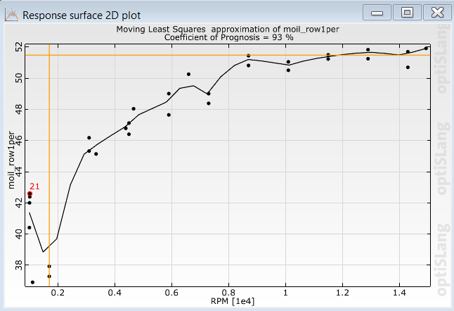
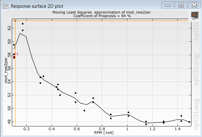
Sensitivity analysis helped to understand the performance of the given design at different operating conditions. Results from sensitivity analysis show equal flow split-up at higher rotational speeds beyond 8000 rpm in the given flow range as shown in Fig 15 and Fig 16. As expected, the flow split-up is more uniform at higher rotational speeds between row1 and row2 as the centrifugal effects dominate over the flow inertia effects. Ansys optiSLang workflow can be easily used for performing process integration and design optimization study by including geometry and other parameters [8].

5. Conclusion
The cooling process of an electric motor is one of the major factors for its performance. In commonly used electric motors, direct oil-cooling is applied where oil is pumped into the rotating shaft and discharged from the tiny nozzles. The design optimization of the hollow, rotating shaft is challenging but crucial for optimum performance. Adopting simulations in the early design stage can significantly reduce the time to market and the overall cost. Though CFD modelling provides an advantage for design optimization, it is challenging to obtain accurate and robust multiphase numerical solutions due to high rotational speeds, varied length scales, and other numerical challenges. This paper describes the solution methodology to overcome all the above-mentioned challenges.
A systematic step-by-step analysis of various flow and modelling parameters was carried out to develop the solution methodology. It is observed that the pseudo-transient solver allows obtaining a steady-state solution significantly faster than the traditional transient approach. The solution methodology proposed in this paper is validated against the experimental data for two-phase flow in a horizontal rotating shaft with twin exit branches. The effect of oil inlet flow rate and rotational speed is analysed for the flow-split, which is crucial for effective cooling. Ansys optiSLang is used to develop a well-integrated and automated workflow from solving to post-processing and is utilized for design sensitivity analysis.
We have also modelled the flow leakage due to clearances between rotating and stationary components using the same methodology, but it is not considered in the scope of this paper. In the same way, we have modelled the effects of bends and plumbing upstream to the inlet, which are not included in this paper. Though isothermal model results are presented in the paper, the same methodology can be extended to non-isothermal modelling with temperature-dependent material properties.
References
[1] B. Assaad, K. Mikati, T. V. Tran and E. Negre, "Experimental Study of Oil Cooled Induction Motor for Hybrid and Electric Vehicles," 2018 XIII International Conference on Electrical Machines (ICEM), Alexandroupoli, 2018, pp. 1195-1200.
[2] W. Tong, Mechanical Design of Electric Motors (1st ed.). CRC Press, 2014.
[3] Y. Gai et al., "Cooling of Automotive Traction Motors: Schemes, Examples, and Computation Methods," in IEEE Transactions on Industrial Electronics, vol. 66, no. 3, pp. 1681-1692, 2019
[4] Maccioni, L.; Concli, F. Computational Fluid Dynamics Applied to Lubricated Mechanical Components: Review of the Approaches to Simulate Gears, Bearings, and Pumps. Appl. Sci. 2020, 10, 8810
[5] Concli, F., Gorla, C. Windage, churning and pocketing power losses of gears: different modeling approaches for different goals. Forsch Ingenieurwes 80, 85–99 2016
[6] Ansys Fluent Theory and User’s Guide, Release 2021R1, Ansys Inc., 2021.
[7] R. Sharma, V. Gupta, A. Khaware and P. Andrade, “Steady State Modeling of Highly Rotating and Viscous Flow using VOF Method for Rotary Glass Fiberization,” Journal of Fluid Flow, Heat and Mass Transfer (JFFHMT), vol. 8, pp 23-32, 2021.
[8] Ansys optiSLang User’s Guide, Release 2021R1, Ansys Inc., 2021.
[9] S. Cheng, W. Yang, "Hysteresis in Oil Flow through a Rotating Tube with Twin Exit Branches", International Journal of Rotating Machinery, vol. 3, Article ID 851802, 10 pages, 1997