Journal of Fluid Flow, Heat and Mass Transfer (JFFHMT)
ISSN: 2368-6111

Volume 9 - Year 2022 - Pages 22-30
DOI: 10.11159/jffhmt.2022.003
Parametric Study of Fluid Injection Winglet on Aerodynamic Performance of the Wing
Hariprasad Thimmegowda1, Yadu Krishnan S1, Gisa G S1, Vootukuri Gowtham Reddy1
1Alliance University, Department of Aerospace Engineering
Chandapura-Anekal Road, Anekal, Bangalore, India- 562102
hariprasad.thimmegowda@alliance.edu.in; yadukrishnan.s@alliance.edu.in
gisa.gs@alliance.edu.in; gowthamrdv9310@gmail.com
Abstract - The possibility of fluid injection winglets for reducing drag without increasing the wingspan of aircraft was investigated in this research. The study used a rectangular baseline wing made of NACA 0012 cross-sectional airfoil with zero-twist and a slot at the wingtip for fluid injections. The commercial CFD tool ANSYS Fluent solver was used to do the computational analysis. For the analysis, numerous parameters such as vertical and downward injection methods, injection velocity range, and range of angles of attack are taken into account. The injection velocities and aerodynamic characteristics such as coefficient of lift, drag, and L/D ratio are shown to have a strong relationship in this simulation. There was an improvement in the distribution of pressure around the wingtip. The reduction of wingtip vortices induced by vertical fluid injection causes a significant increase in the L/D ratio. In comparison to the upward injection method with increased angles of attack, the results reveal that downward fluid injection is better at enhancing aerodynamic efficiency.
Keywords: Induced drag, Winglets, Fluid injection, CFD.
© Copyright 2022 Authors - This is an Open Access article published under the Creative Commons Attribution License terms Creative Commons Attribution License terms. Unrestricted use, distribution, and reproduction in any medium are permitted, provided the original work is properly cited.
Date Received: 2022-01-24
Date Accepted: 2022-01-31
Date Published: 2022-02-07
1. Introduction
Aircraft engines discharge gases and airborne particles predominantly into the upper troposphere and lower stratosphere, changing the composition of the atmosphere. These chemicals and particulates influence the concentrations of greenhouse gases, such as carbon dioxide (CO2), ozone (O3), and methane (CH4), as well as the formation of condensation trails (contrails) and cirrus clouds, contribute to climate change. In addition, fuel prices are soaring. As a result, reducing fuel usage in aircraft becomes critical.
A significant amount of research is being done to find ways to reduce specific fuel consumption. Researchers are working to reduce fuel usage by designing lighter, more efficient engines. To minimize the weight of the aircraft, lighter weight and higher strength aircraft materials are being used. Additionally, small, lightweight wireless transceivers are being investigated as a possible replacement for wiring in some non-avionic systems, such as those that regulate cabin illumination, cabin pressure, landing gear, and door sensors. Reducing an aircraft's lift-to-drag ratio can improve its aerodynamic efficiency while also lowering its weight and fuel consumption. Engineers are experimenting with new designs that will aid in the reduction of drag.
An aircraft designer's primary objective is to improve aerodynamic efficiency. The contour of an airfoil, lifting surfaces, the airfoil's orientation to the flow, air density and viscosity, compressibility effects, freestream velocity, and the surface area over which the air flows all influence lift generation. One of the major contributors to overall drag is a lift-induced drag, which can be reduced by weakening the trailing vortices. In 1970, the author [1] investigated the late-nineteenth-century winglet design patented by F W Lancaster. Winglets were shown to minimize induced drag by around 20% and boost the lift-drag ratio by roughly 9%, as per this research. The wind tunnel studies indicated increased aerodynamic and cruise efficiency by incorporating winglets on wingtips. Since then, several different types of winglet designs have been studied to improve aerodynamic performance.
Aspiroid-tipped wing [2, 3] that bends upward by 360 degrees to form a ribbon and multi-element winglets [4-7] with varied cant angles and element configurations that mimic birds were developed. Qualitative and quantitative optimization evaluations on blended winglets and split blended wings have been investigated to increase wing performance [8-12]. The author [13] implemented winglets on a saucer-shaped plane that was manufactured by integrating the fuselage and the wing. When a sweep-back fin-shaped winglet is added, the lift-to-drag ratio rises by 75%, and the coefficient of lift enhances as well. The study also discovered that employing the winglets improves load capabilities and lateral stability in flight tests. All of these research point to an increase in aerodynamic efficiency.
Winglets are a structural change that serves as a permanent attachment for the complete flight envelope. Winglets are effective at reducing induced drag; nevertheless, the addition of winglets may result in an increase in drag due to surface friction. Retrofitting the winglets can change the handling characteristics [14]. Because of aeroelastic effects, the wing twist changes, affecting the aircraft's performance. The effect of the winglet on long-range aircraft was studied by the authors [15-17]. According to this study, winglets cause flutter and add extra mass to the wingtips, which causes rolling inertia and increases the bending load.
During steady-level flight, the angle of attack is low. As a consequence, the contribution of induced drag to the total drag is reduced. Though, due to the increased angle of attack, it makes a significant contribution during landing and takeoff. As a result, when the necessity arises, it is wise to use a winglet. This is impossible to achieve with a permanent winglet. The influence of fluidic winglets on the aerodynamic efficiency of the wing on demand was examined by the authors [18]. Fluid is injected into flow in a horizontal direction at the wingtip in the reference [18].
In this study, an on-demand solution, a fluidic winglet, is investigated as a replacement for a permanent winglet. The fluid will be pushed in a vertical direction (both upward and downward) at the wing's tip. The flow at the wingtip will be altered when the fluid is injected vertically. A computational investigation was performed to determine the impact of introducing fluid on-demand at the wingtip in the vertical direction.
2. Model Geometry
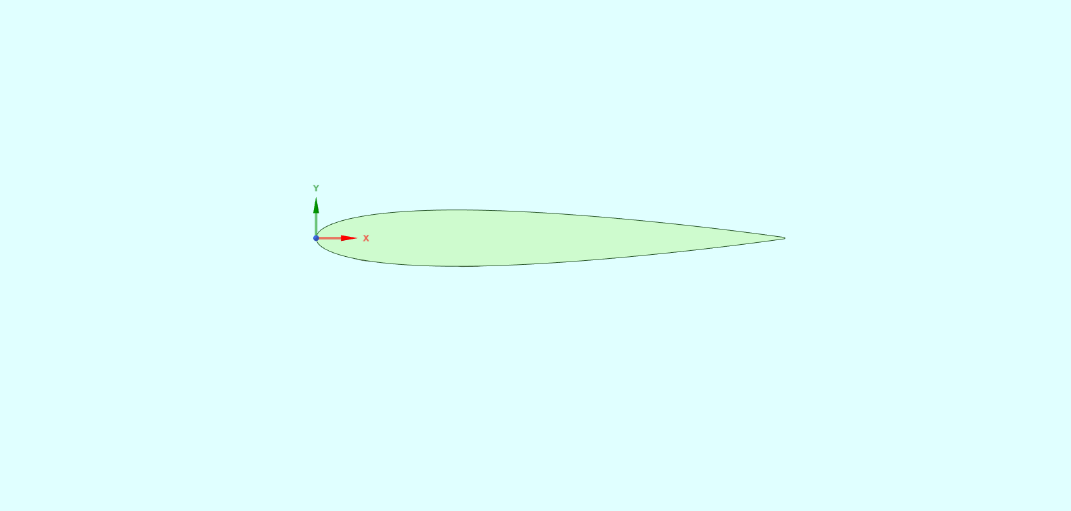
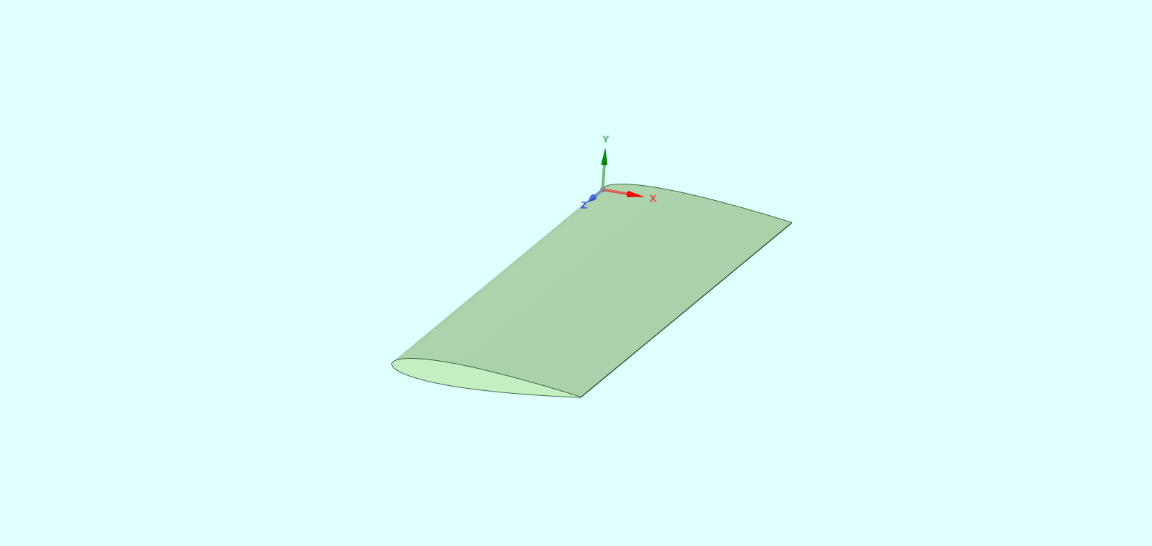
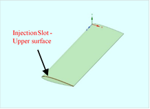
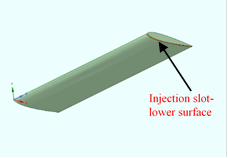
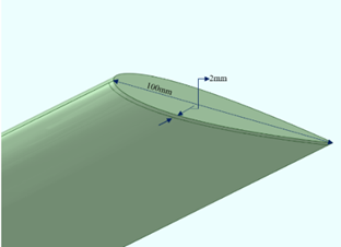
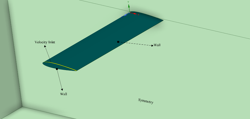
The main platform on which the fluidic winglets will be placed is a rectangular, untwisted, no dihedral, and unswept airfoil geometry developed with a NACA 0012 profile. This will be referred to as the baseline wing. The wing will have a chord of 100 mm and a span of 300 mm. An aspect ratio of 3 was considered. Figure 1 depicts the airfoil section of the wing under consideration. The slot on the upper and lower surface of the wing is 2 mm wide at the tip. As shown in Figure 3, the injection slot is generated from the leading edge to the trailing edge.
3. Computational Details: Computational Domain, Mesh, Boundary Conditions, And Solution Methods
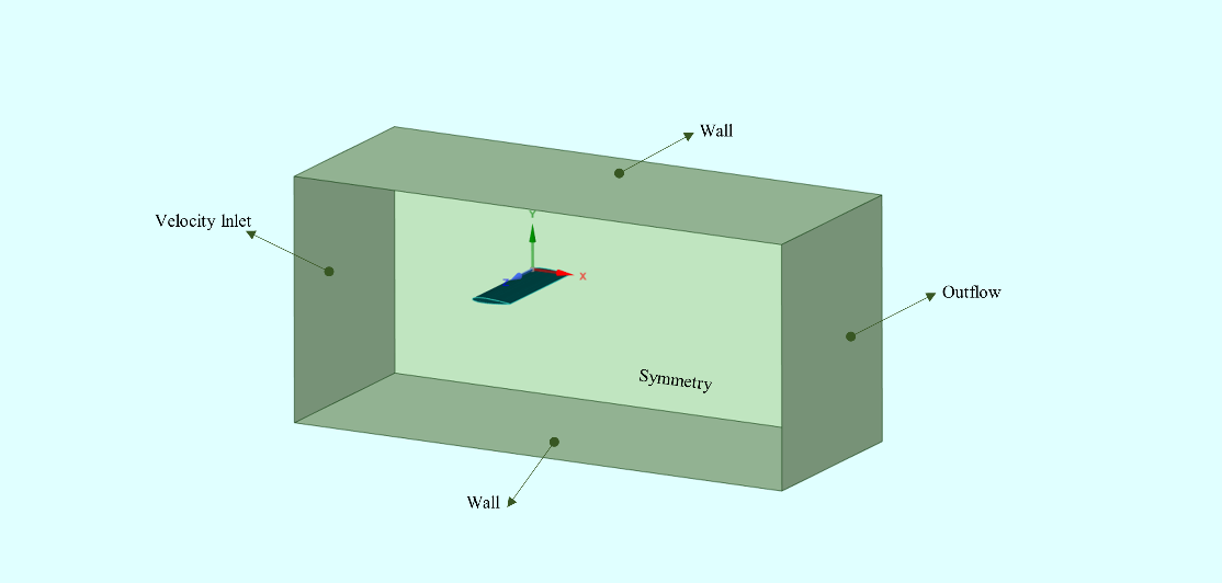
The cartesian coordinate system is used to define the domain. The wing's trailing edge, topside, and wingtip were pointing in the direction of X, Y, and Z, respectively. The inlet, outlet, top, and bottom domain boundaries were positioned 5c, 8c, and 3c from the trailing edge of the root of the wing, respectively. The letter c stands for chord length. 2c is the distance between the wingtip and the sidewall. This rectangular domain is analogous to the test section of the wind tunnel. For the analysis, the control volume for the baseline wing, with and without fluid injection, is identical.
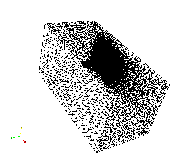
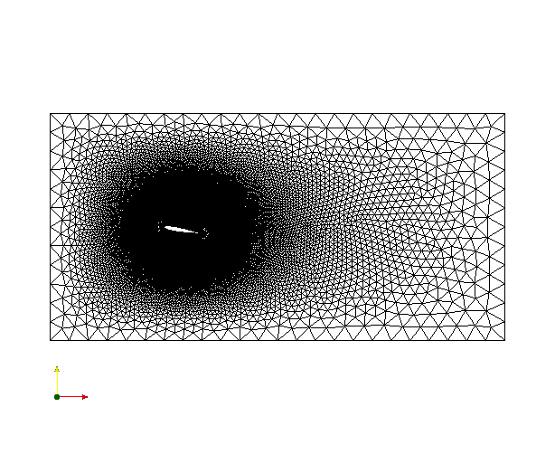
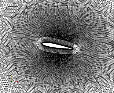
For the computational study, an unstructured mesh formed of tetrahedral elements was constructed using cutting-edge grid generating tools. Since the gradient in flow properties like velocity and pressure are high near the wing, a fine mesh is generated around the wing surface using the sphere of influence method, and the flow properties gradient is so small far away from the wing surface, a coarse mesh is used in this area. Inflation layers have been given to capture gradient information at the fluid-surface boundaries. Figure 4 shows an image of the computational domain.
For the upstream boundary, a velocity inlet boundary condition was employed, with inlet velocity, turbulence intensity, and length scale values specified. The outlet boundary was subjected to a pressure far-field boundary condition, while the rest of the domain faces were treated as slip walls. The velocity and ambient pressure at the inlet are 20 m/s and 1 atm, respectively. The injection slot has a velocity inlet, as indicated in figure 5.
The numerical study was done using the CFD tool ANSYS Fluent software. The k-epsilon turbulence model has been chosen to simulate the flow characteristics. This model can be used to produce an acceptable boundary layer solution.
4. Results and Discussions
The baseline wing, set at an AOA of 10 deg, is being used for validation in this case. This flow case has previously been shown by Ananda GK, Sukumar PP, & Selig MS [19], as an experimental work in the wind tunnel for various wings with aspect ratios ranging from 2 to 5. The numerical results, on the baseline wing, with the K-Epsilon turbulence model were solved using the ANSYS package. The lift and drag coefficients are directly obtained by the post-processor. Table 1, compares the drag and lift values produced from numerical simulations with the experimental results. Due to better mesh quality, the CFD results are in extremely good agreement with the experimental data, as shown in table 1.
Table- 1. Validation of CFD results with Experimental result
|
Coefficients |
Experiment result [19] |
CFD result |
|
CL |
0.6 |
0.654 |
|
CD |
0.12 |
0.1107 |
4.1 Baseline
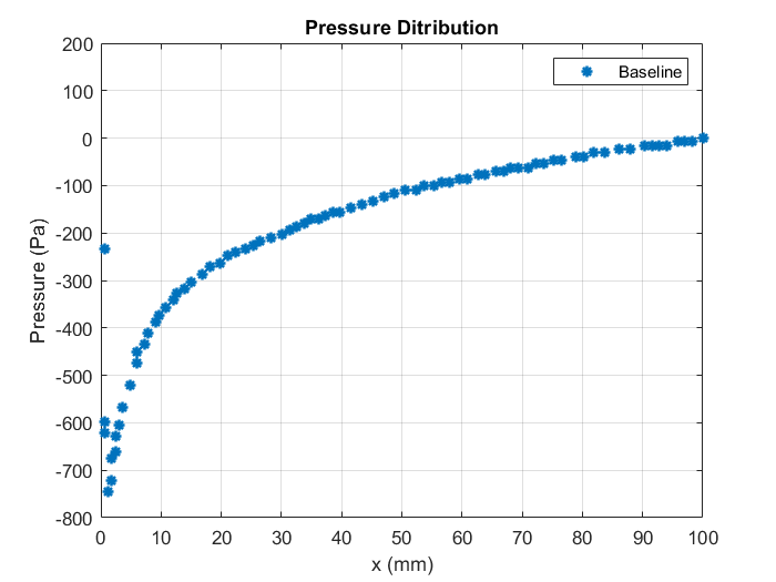
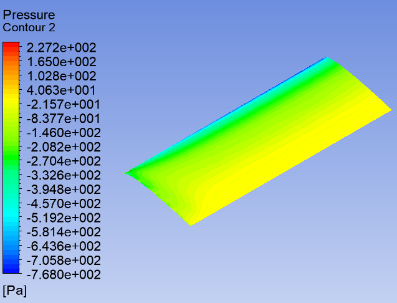
The pressure contours, for the baseline wing at a 10o angle of attack, can be seen in Figure 6. It is clearly visible on the bottom surface of the baseline wing, the pressure at the leading edge is increased. However, on the top surface, the pressure is comparable with the ambient pressure at the leading edge. This suggests that the flow accelerates faster on the upper surface compared to the lower surface of the wing. Figure 7 illustrates the pressure distribution on the top surface of the baseline wing along the chord length, which confirms the increase in flow speed. On both the top and bottom surfaces of the baseline wing, the pressure distribution after the leading edge shows a considerable decrease in the downstream direction before returning to its reference freestream pressure values. Nevertheless, the pressure contour implies that the pressure is equalized on both the upper and lower surface by the time it reaches the trailing edge.
 (a)
(a)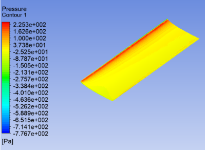 (b)
(b)
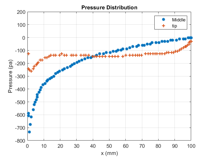
Figure 8 shows a comparison of pressure distribution at two-span positions on the top surface of the baseline wing. Except at the leading and trailing edges, the pressure at the wingtip is nearly constant along the chord length. This is in contrast to the pressure distribution in the middle section of the wing, which appears to be normal.
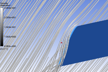
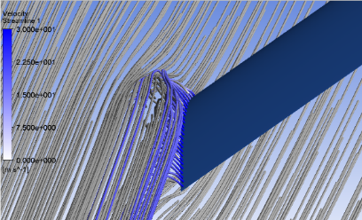
A small vortex can cause such a flow near the tip of the wing, which swells in size as it moves downstream. The flow downstream appears to change direction along the wingspan towards the wingtip due to the presence of the wingtip vortex.
4.2 With fluid Injection
The fluid is injected into the airstream from the slots created at the wingtip. The numerical simulation was carried out for fluid injection velocities of 10 m/s, 20 m/s, 30 m/s, and for three angles of attacks 6 deg, 8 deg, 10 deg. The fluid was introduced into the stream under two conditions: (i) the flow enters the stream through the upper slot only (ii) the flow enters the stream through the lower slot only. Figure 9(a) shows the pressure contour on the top surface of the wing with a fluid injection velocity of 30 m/s in an upward vertical direction. The wing is set at an angle of attack of 10o. It appears that the injection of fluid at the wing tip alters the pressure distribution around the tip.
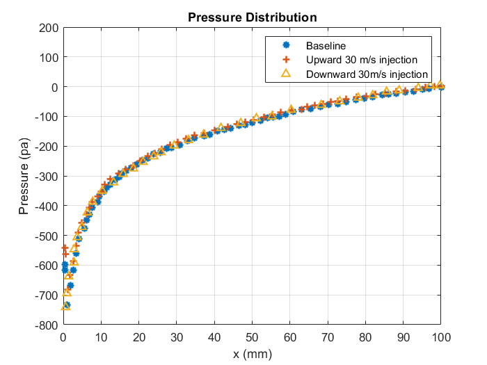
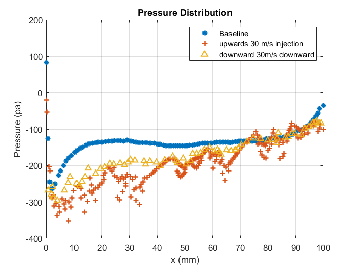
The pressure distribution without injection, with upward and downward injection velocities of 30 m/s and at an angle of attack of 10o and midspan (z = 150 mm) location is shown in figure 10. The pressure distribution for baseline wing (without injection), and wing with upward and downward injection velocity is comparable. However, at the wingtip, there are large variations in pressure distributions for baseline wing and wing with slots as illustrated in figure 11. The vortex strength is reduced near the tip due to the presence of fluid injection at the tip. It is also noted that the flow is unaffected at the midsection.
 (a)
(a)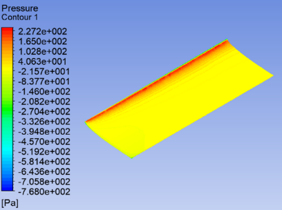 (b)
(b)
 a)
a)
 b)
b)
4.3 Variation of aerodynamic coefficients
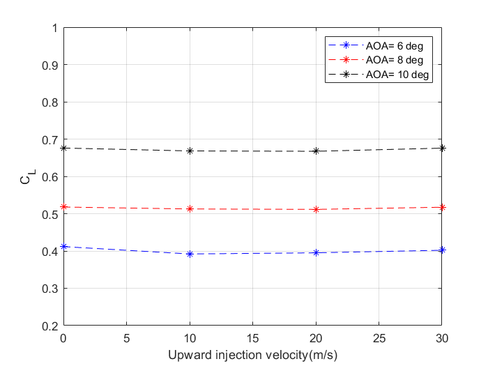
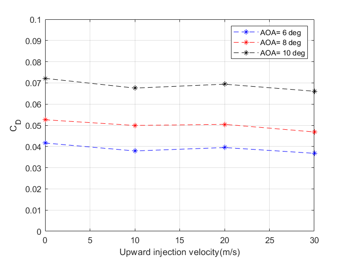
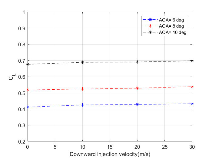
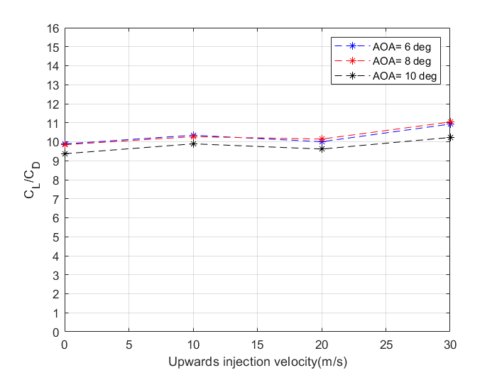
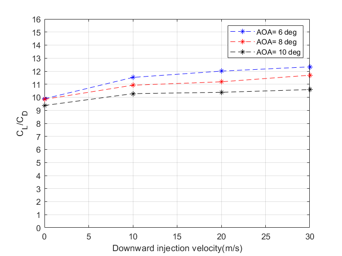
The variation of lift and drag coefficients and lift to drag ratio for various speeds and AOA’s with upward injection velocities are illustrated in figures 13 to 15. It can be noted that, for all angles of attack, the lift remains constant while the drag decreases slightly as injection velocity increases for the case of vertically upward fluid injection. The drag reduction is over 20%. This implies that there is a reduction in drag due to the trailing vortex. Consequently, the lift-drag ratio increases as the fluid injection velocities increase for all angles of attack. However, there is an increase in lift coefficient in the case of downward fluid injection when the injection velocity increases as shown in figure 16. Figure 17 depicts the variation of coefficient of drag to increase in downward fluid injection velocities which shows a reduction in the drag coefficient. This causes a significant increase in CL/CD as shown in figure 18.

5. Conclusions
Using a numerical technique, the effect of fluid injection, which uses a slot at the wingtip to inject fluid vertically in an upward and downward direction, on the efficiency of a 3D wing at velocities of 10 m/s, 20 m/s, and 30 m/s was investigated at angles of attack of 6 deg, 8 deg, and 10 deg at velocities of 10 m/s, 20 m/s, and 30 m/s. At angles of attack of 6 degrees, 8 degrees, and 10 degrees, the CL remains constant for all upward injection velocities. In the event of downward injection velocities, however, the CL value increases. At all angles of attack, the coefficient of drag decreases with the increase in fluid injection velocities in both situations.
The numerical study suggests that the wingtip with upward and downward vertical injection systems will produce better lift coefficient characteristics when compared to the horizontal injection system. In turn, lift-drag ratios are enhanced. However, the drag coefficient is larger for the vertical fluid injection system in comparison with the horizontal injection system at lower angles of attack. Henceforth, it can be established that horizontal injection systems are superior at lower angles of attack, whereas vertical injection systems are better at higher angles of attack. When done appropriately, the fluid injection can be a great alternative to typical wingtip devices.
References
[1] Whitcomb, Richard T. “A Design Approach and Selected Wind-Tunnel Results at High Subsonic Speeds for Wing-Tip Mounted Winglets,”. Washington: National Aeronautics and Space Administration, 1976.
[2] Gratzer LB, inventor; Gratzer Louis B, assignee. “Spiroid-tipped wing,”. United States patent US 5,102,068. Apr 7, 1992.
[3] J. Guerrero, D. Maestro and A. Bottaro, "Biomimetic spiroid winglets for lift and drag control," Comptes Rendus Mécanique, vol. 340, no. 1-2, pp. 67-80, 2012. Available: 10.1016/j.crme.2011.11.007. View Article
[4] Hossain A, Rahman A, Hossen J, Iqbal P, Shaari N, Sivaraj GK. “Drag reduction in a wing model using a bird feather like winglet,” Jordan Journal of Mechanical and Industrial Engineering, June 1, 2011,5(3).
[5] Reddy SR, Sobieczky H, Dulikravic GS, Abdoli A. “Multi-element winglets: multi-objective optimization of aerodynamic shapes,” Journal of Aircraft. July 2016, 53(4):992-1000. View Article
[6] Giridharan V, Kumar KM, Elumalai N, Sundararaj M. “Computational study of effectiveness of winglet at subsonic speed,”. In AIP Conference Proceedings Sep 28, 2020 (Vol. 2271, No. 1, p. 030028). AIP Publishing LLC. View Article
[7] Smith M, Komerath N, Ames R, Wong O, Pearson J. “Performance analysis of a wing with multiple winglets,” In 19th AIAA Applied Aerodynamics Conference 2001 (p. 2407). View Article
[8] Gratzer LB, inventor; Gratzer Louis B, “Blended winglet,” United States patent US 5,348,253, Sep 20,1994
[9] Belferhat, S., S. M. A. Meftah, T. Yahiaoui, and B. Imine. “Aerodynamic Optimization of a Winglet Design,” In EPJ Web of Conferences, vol. 45, p. 01010. EDP Sciences, 2013. View Article
[10] Khosravi, Shahriar, and David W. Zingg. “A numerical optimization study on winglets,” In 15th AIAA/ISSMO multidisciplinary analysis and optimization conference, p. 2173. 2014. View Article
[11] Gratzer, Louis B. "Split blended winglet," U.S. Patent 8,944,386, issued February 3, 2015.
[12] Reddy, Sohail R., George S. Dulikravich, Abas Abdoli, and Helmut Sobieczky. “Multi-winglets: Multi-objective optimization of aerodynamic shapes,” In 53rd AIAA Aerospace Sciences Meeting, p. 1489. 2015. View Article
[13] YU JL, WANG LL, Ge G. “Using wing tip devices to improve performance of saucer-shaped aircraft,” Chinese Journal of Aeronautics, Nov 1, 2006,19(4):309-14. View Article
[14] Van Dam C P, Holmes BJ, Pitts C. “Effect of winglets on performance and handling qualities of general aviation aircraft,” Journal of Aircraft, July 18, 1981 (7):587-91. View Article
[15] Delavenne M, Barriety B, Vetrano F, Ferrand V, Salaun M. “Assessment of the efficiency of an active winglet concept for a long-range aircraft,” CEAS Aeronautical Journal. Dec 11, 2020 (4):971-90. View Article
[16] Hantrais-Gervois JL, Rapin M. “Aerodynamic and structural behaviour of a wing equipped with a winglet at cruise,” In 44th AIAA Aerospace Sciences Meeting and Exhibit, Jan, 2006, (p. 1489). View Article
[17] Odaguil, Felipe Issamu Kitadani, A. Pequeno Antunes, Pedro Paglione, and João Luiz F. Azevedo. “Performance assessment of a morphing wingtip device,” In International congress of mechanical engineering, Ribeirao Preto, Br. 2013.
[18] Rajesh A, Badri RA, Prasad MS. “Numerical Analysis on the Effect of Fluidic on Demand Winglet on the Aerodynamic Performance of the Wing,” Journal of Aeronautics and Aerospace Engineering, 2017,6(3):198-203. View Article
[19] Ananda GK, Sukumar PP, Selig MS. “Measured aerodynamic characteristics of wings at low Reynolds numbers,” Aerospace Science and Technology, April 1, 2015 42:392-406. View Article
[20] Abbott IH, Von Doenhoff AE. “Theory of wing sections: including a summary of airfoil data,” Courier Corporation, Apr 26, 2012
[21] Thimmegowda, H., S, Yadu Krishnan. and G S, Gisa. “Computational Study on Wingtip Vertical Fluid Injection for Induced Drag Reduction”, In Proceedings of 8th International Conference on Fluid Flow, Heat and Mass Transfer (FFHMT'21), May 2021 View Article