Journal of Fluid Flow, Heat and Mass Transfer (JFFHMT)
ISSN: 2368-6111

Volume 9 - Year 2022 - Pages 01-09
DOI: 10.11159/jffhmt.2022.001
Numerical Simulation of Innovative Air Capture Systems Based on Bladeless Technology with Coandă Effect
Maurizio Carlini1, Andrea Mennuni1, Mirko Rotondo2, Stefano Morelli2
1University of Tuscia, CIRDER
Largo dell’Università, 01100 Viterbo, Italy
maurizio.carlini@unitus.it; andrea.mennuni@unitus.it
2University of Tuscia, DEIm
Largo dell’Università, 01100 Viterbo, Italy
mirko.rotondo@unitus.it; stefano.morelli894@gmail.com
Abstract - This work focuses on the feasibility study of a new suction hood model that allows the complete disposal of the fumes produced during cooking. The originality of this study lies in the conception of a new functional geometry meant to reduce consumption, focusing on the increase of both efficiency and aspiration efficiency. The new technology is based on the Coandă effect applied on two innovative air capture systems of hood model. On one hand the air flow amplifier, a system that, starting from a low inlet flow rate, allows 10 times increasing of the output flow rate. On the other hand, the bladeless fan, which is usually implemented in newest bladeless ventilation systems. A simulation campaign has been conducted with COMSOL Multiphysics software to validate the simulation scenarios comparing the experimental results with respective references. For the post-validation step, the parametric sweep function has been used to study the system behaviours to every change of velocity, flow rate and extension of the ejector. The obtained results show the feasibility of these new suction systems, which present lower consumptions than other modern ventilation systems for kitchens. The computed results show that the perimeter velocity is in accordance with European standards. The perimeter velocity for air flow amplifier geometry allows a suction capacity range between 460 m3/h and 3600 m3/h. In the bladeless fan case, the suction capacity is in a range between 325 m3/h and 2500 m3/h. Therefore, the two geometries can be installed for both domestic and commercial kitchens.
Keywords: Bladeless technology; Coandă effect; air capture system; extractor hood; COMSOL Multiphysics; CFD analysis; multiparametric analysis.
© Copyright 2022 Authors - This is an Open Access article published under the Creative Commons Attribution License terms Creative Commons Attribution License terms. Unrestricted use, distribution, and reproduction in any medium are permitted, provided the original work is properly cited.
Date Received: 2021-08-26
Date Accepted: 2021-12-22
Date Published: 2022-01-17
1. Introduction
In order to reduce pollution emissions, innovative technologies are growing in accordance with current EU standards in terms of energy efficiency, in coupling with the renewable sources.
Hoods for fumes extraction are present in all homes, inside industries and in catering environments. Their main function, especially in the kitchen environment, is to extract the cooking fumes, improving the air quality where the device is installed [1]. Clearly, the position is a crucial consideration, since an incorrect placement leads to fumes and pollutants stagnation inside the dwelling [2]. For a correct ejection of the produced fumes, a fan must be installed to allow and guarantee a sufficient prevalence and flow rate, managing to overcome the load losses generated by the presence of the filter (to remove solid particles and liquids of grease and steam contained by the fluid crossing the hood) [3]–[5].
The design of the aspiring systems must be provided in accordance with different European standards and requirements. Moreover, the size and type (professional or domestic) of the installation environment have to be considered. The fundamental parameter is the calculation of the right suction flow for the disposal from the surrounding environment, of the main cooking fumes pollutants, in order to avoid the spread of contaminants inside the housing structure [6]–[9]. Proper design finds the right compromise between the aspirated flow rate that allows the disposal of all pollutants and the higher energy efficiency [10], [11], always in accordance with EU directives [12]. In fact, the world is moving to sustainable principles by means of known technologies optimization, such as for the building sector [13], [14], for the photovoltaic system [15], [16], for the biological conversion [17]–[19] using different input biomasses [20]–[22] and for the geothermal field [23], [24]. The study of these technologies can be extended by a simulation software, allowing the development of numerical campaigns on virtual prototypes [25], [26], reducing the production costs in the meanwhile [27], [28].
This work aims to define the velocity field of n. 2 hood models with bladeless technology through COMSOL Multiphysics software, validating the simulation scenarios with the reference data. Then, a parametrization is used to change the geometry (ejectors), velocity and flow rate, observing the feasibility and the behavior of the systems. The various advantages of the installation of the bladeless technology are the absence of moving parts in the suction area (vibrations are not produced), reduced cleaning and maintenance, low noise, high suction capacity, reduced weight and consumption.
2. Materials and methods
2. 1. Experimental Characterization
The study involves the collection of bibliographical data that will be used as a reference for numerical simulations. Two different geometries are analyzed, a first geometry called Air flow amplifier, basically an air amplifier, and a second one called Bladeless fan. Both of these models take advantage of the Coandă effect which leads to an increase in terms of output flow, which is even 10 times higher than the inbound one. In particular, for the Air flow amplifier, several elaborations concerning optimization and CFD simulation (Computational Fluid Dynamics) have been reported by [29], [30], while for the Bladeless fan the main reference has been provided by the engineering company BW Engineering © and the company Dassault Systèmes ®, developer of the Abaqus software and CAD software SolidWorks ®. For both models, given the high complexity, CAD-based software has been used to extrapolate the correct measurements. Therefore, several papers have been analyzed for the Bladeless fan [29], [30]: for both geometry [31]–[33] and simulation conditions the geometry a tutorial by the engineering company BW Engineering has been chosen [34].
2. 2. Main Physical Phenomena Identification and Implementation
The Coandă effect indicates that a flow flowing over a surface is influenced by two simultaneous forces. The global effect is a deviation of the fluid layers near the surface, as such layers show a tendency to adhere to the same surface [35]. Multiple applications have been developed about Coandă effect, leading to significant improvements both in aeronautics [29] and in medicine [36], [37].
The analysis is carried out through COMSOL Multiphysics (CM), a multiphysical simulations software which provided a multidisciplinary approach to the physics and phenomena to implement within the scenario. CM resolution approach is based on the Finite Element Method (FEM) to solve physical models and engineering problems [38]–[40]. Several papers have been consulted to understand the phenomenon before its implementation in CM [41]–[43]. In this particular case, axisymmetric 2D geometry is chosen as a spatial dimension and the CFD module is used for physics. By means of the CFD module, as provided by CM, it is possible to model in the same scenario environment both the heat transfer to solids or fluids and reagent flows. In this study, the "Turbulent Flow" interface of the "Single-Phase Flow" model contained within COMSOL Multiphysics's "Fluid Flow" module is selected [44].
2. 3. Simulation Campaign
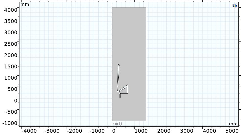
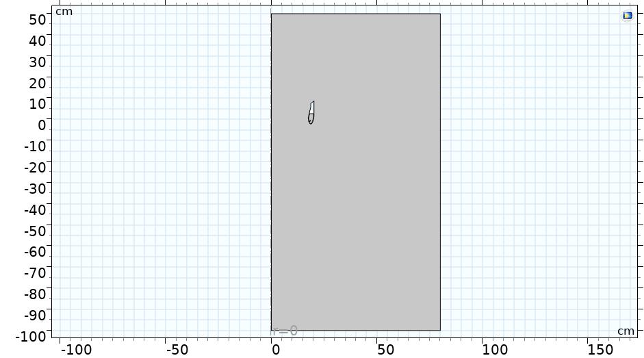
The strategy of the simulation campaign is based on the reference data obtained by bibliography. The full geometry is defined in CM as shown by Figure 1a and Figure 1b for the Airflow amplifier and Bladeless fan, respectively.
 (a)
(a)
 (b)
(b)
Once the geometry is designed, it is possible to pass through the materials selection and assignment. In this case the material that needs to be selected is air. The boundary conditions made for the study of turbulent flow k – are the following: wall (No slip), inlet where the mass flow (min=0,25 kg/s) is inserted for the Air flow amplifier model while the condition of velocity (vin=2 m/s) is implemented for the Bladeless fan model, outlet by using the pressure condition for both geometries and open contour to identify the boundary where incoming and outcoming fluxes are possible. Then, the model is meshed and calculated by means of a stationary approach. The simulation output is the 2D velocity across the whole geometry. Once the scenarios have been validated, a parametric sweep is conducted to carry out a wider analysis. In this case, for both geometries a sweep is initialized referring to n. 2 parameters and, for each of them, 4 different values are considered. It follows that n. 16 scenarios are solved. Referring to the Air flow amplifier scenario, the flow rate (min) and the curvature of the arcs (that influences the ejector opening) change, as defined by Table 1. In the case of the Bladeless fan scenario, the velocity (vin) and the point that defines the ejector opening vary, as defined by Table 1. The different combinations allow the study of the velocity field of the two systems as the inlet conditions and the ejector opening change. Then, it is possible to identify which configuration should be used for a specific application.
Table 1. Parametric sweep for the Air flow amplifier.
|
|
Parameter |
Value |
|||
|
Air flow amplifier |
ejector [mm] |
0,30 |
0,50 |
0,55 |
0,65 |
|
min[kg/s] |
0,10 |
0,15 |
0,20 |
0,25 |
|
|
Bladeless fan |
ejector [mm] |
1,00 |
1,15 |
1,30 |
1,40 |
|
vin[m/s] |
1,00 |
2,00 |
3,00 |
4,00 |
|
3. Results
3. 1. Numerical scenarios validation
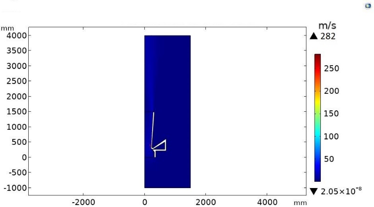
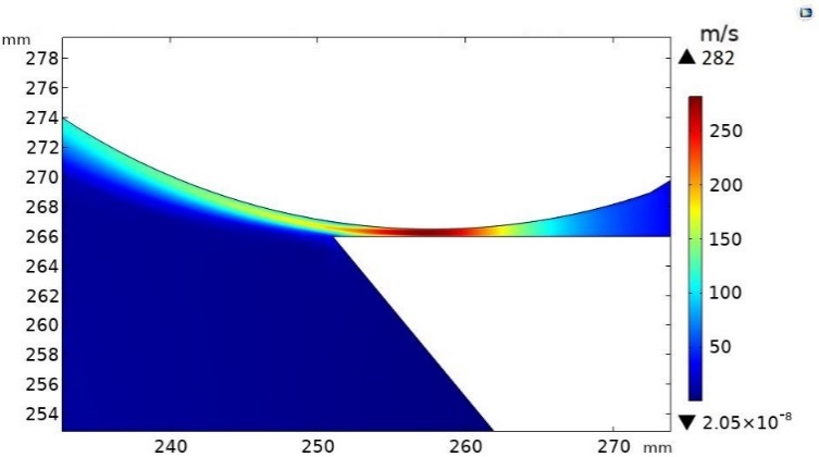
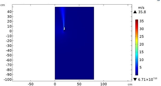
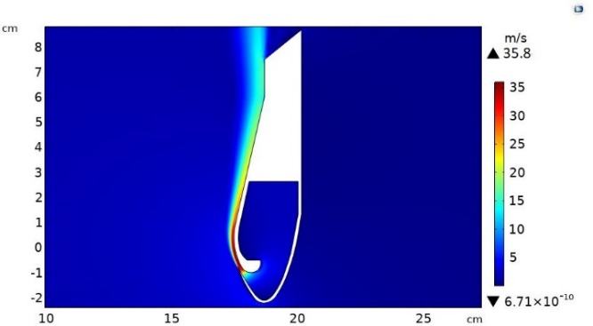
The first step is the validation of the scenarios comparing the results obtained by numerical simulation (from COMSOL Multiphysics) with the ones by reference data. The maximum discrepancy of these results has been fixed up to 5.0%, which follows the scenario validation. The velocity field in the whole geometry is reported by Figure 2 and Figure 3 for the Air flow amplifier and Bladeless fan scenarios, respectively. Calculating the discrepancies in different points, the obtained values satisfy the discrepancy requirement for both models, therefore the numerical scenarios can be considered validated.
 (a)
(a)
 (b)
(b)
 (a)
(a)
 (b)
(b)
More in details, once validating numerical scenarios, Table 2 defines the simulation results compared with the reference data to calculate the discrepancy for the Air flow amplifier and Bladeless fan models.
Table 2. Validation of the models with the reference values for both Air flow amplifier [29] and Bladeless fan [34] scenarios.
|
Model |
Value |
Reference data [m/s] |
Simulation result [m/s] |
Discrepancy [%] |
|
Air flow amplifier |
max. vel. |
281,50 |
282,00 |
0,18 |
|
ejector output vel. |
200,00 – 210,00 |
203,00 |
1,50 – 3,33 |
|
|
vel. on curvature |
180,00 |
174,00 |
3,33 |
|
|
Bladeless fan |
max. vel. |
35,09 |
35,80 |
2,02 |
|
queue vel. |
15,00 – 16 ,00 |
15,58 |
3,87 – 2,63 |
3. 1. Parametric analysis
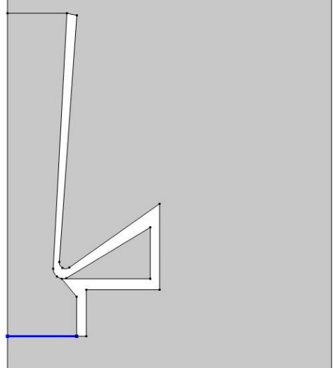
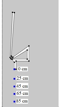
Explicit selections were created through the "Definitions" section of CM, which were then used to calculate the average and point velocities at different distances. Figure 4 and Figure 5 represent the explicit selections used to calculate the average inbound velocity and the velocity at different distances from the perimeter edge for the Air flow amplifier and Bladeless fan model, respectively.
(a)
(b)
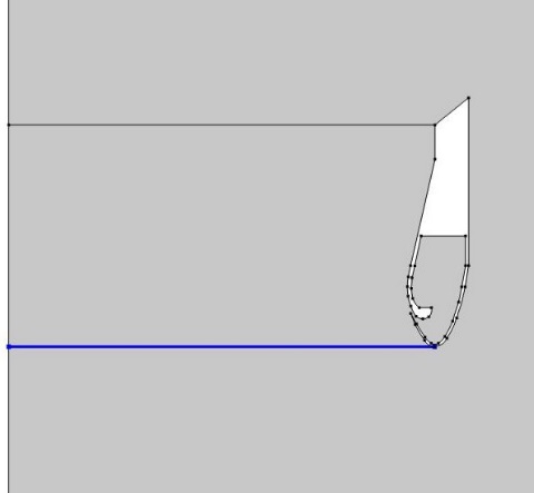
(a)
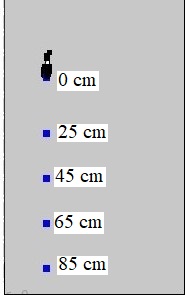
(b)
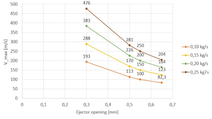
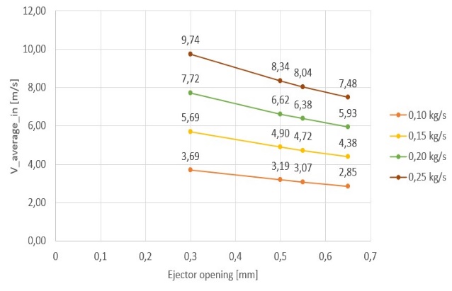
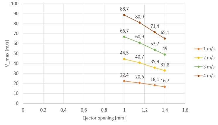
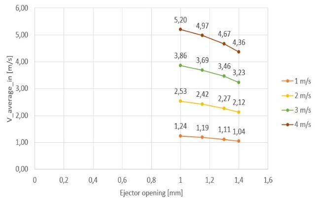
Different graphs have been constructed to understand the trend of the maximum velocity and the average velocity in the inbound section. In particular, Figure 6 shows the trend of the maximum velocity and the average inbound velocity changing the ejector opening and the inlet flow rate (min) for the Air flow amplifier, while Figure 7 shows the trend of the maximum velocity reached in the section of the rejector and the average inbound velocity changing the ejector opening and the inlet velocity (vin) for the Bladeless fan.
 (a)
(a)
 (b)
(b)
 (a)
(a)
 (b)
(b)
In Table 3, the velocity results are reported depending on the opening of the ejector and the distance from the edge of the hood in different values of inlet flow rate for the Air flow amplifier. In Table 4, the velocity results are reported depending on the opening of the ejector and the distance from the edge of the hood in different values of inlet velocity for the Bladeless fan. Results highlighted in red identify the perimeter velocities that need to be compared with the minimum ones eligible by the European standards.
Table 3. Perimeter velocity values at different heights for different ejector openings and inlet flow rates (Air flow amplifier).
|
|
AE / Point |
Vel. at different heights [m/s] |
||||
|
0 cm |
25 cm |
45 cm |
65 cm |
85 cm |
||
|
min= 0,10 kg/s |
0,30 [mm] |
0,68 |
0,66 |
0,36 |
0,18 |
0,09 |
|
0,50 [mm] |
0,53 |
0,50 |
0,31 |
0,16 |
0,08 |
|
|
0,55 [mm] |
0,48 |
0,45 |
0,30 |
0,15 |
0,07 |
|
|
0,65 [mm] |
0,40 |
0,38 |
0,28 |
0,14 |
0,07 |
|
|
|
||||||
|
min= 0,15 kg/s |
0,30 [mm] |
1,45 |
1,19 |
0,55 |
0,28 |
0,14 |
|
0,50 [mm] |
1,14 |
1,02 |
0,48 |
0,24 |
0,12 |
|
|
0,55 [mm] |
1,05 |
0,98 |
0,46 |
0,23 |
0,11 |
|
|
0,65 [mm] |
0,89 |
0,91 |
0,42 |
0,21 |
0,10 |
|
|
|
||||||
|
min= 0,20 kg/s |
0,30 [mm] |
2,31 |
1,61 |
0,75 |
0,38 |
0,19 |
|
0,50 [mm] |
1,92 |
1,38 |
0,64 |
0,32 |
0,16 |
|
|
0,55 [mm] |
1,76 |
1,33 |
0,62 |
0,31 |
0,15 |
|
|
0,65 [mm] |
1,51 |
1,23 |
0,57 |
0,29 |
0,14 |
|
|
|
||||||
|
min= 0,25 kg/s |
0,30 [mm] |
3,08 |
2,02 |
0,94 |
0,47 |
0,24 |
|
0,50 [mm] |
2,64 |
1,74 |
0,81 |
0,41 |
0,20 |
|
|
0,55 [mm] |
2,44 |
1,67 |
0,78 |
0,39 |
0,19 |
|
|
0,65 [mm] |
2,14 |
1,55 |
0,72 |
0,36 |
0,18 |
|
Table 4. Perimeter velocity values at different heights for different ejector openings and inlet velocities (Bladeless fan).
|
|
AE / Point |
Vel. at different heights [m/s] |
||||
|
0 cm |
25 cm |
45 cm |
65 cm |
85 cm |
||
|
vin= 1,0 m/s |
1,00 [mm] |
1,25 |
0,15 |
0,06 |
0,03 |
0,01 |
|
1,15 [mm] |
1,20 |
0,14 |
0,06 |
0,03 |
0,01 |
|
|
1,30 [mm] |
1,13 |
0,13 |
0,05 |
0,03 |
0,01 |
|
|
1,40 [mm] |
1,06 |
0,12 |
0,05 |
0,02 |
0,01 |
|
|
|
||||||
|
vin= 2,0 m/s |
1,00 [mm] |
3,10 |
0,30 |
0,12 |
0,06 |
0,02 |
|
1,15 [mm] |
2,97 |
0,29 |
0,12 |
0,05 |
0,02 |
|
|
1,30 [mm] |
2,72 |
0,26 |
0,11 |
0,05 |
0,02 |
|
|
1,40 [mm] |
2,52 |
0,25 |
0,10 |
0,05 |
0,02 |
|
|
|
||||||
|
vin= 3,0 m/s |
1,00 [mm] |
5,18 |
0,46 |
0,19 |
0,09 |
0,03 |
|
1,15 [mm] |
5,00 |
0,44 |
0,18 |
0,08 |
0,03 |
|
|
1,30 [mm] |
4,63 |
0,40 |
0,17 |
0,08 |
0,03 |
|
|
1,40 [mm] |
4,30 |
0,38 |
0,16 |
0,07 |
0,03 |
|
|
|
||||||
|
vin= 4,0 m/s |
1,00 [mm] |
7,26 |
0,61 |
0,25 |
0,11 |
0,04 |
|
1,15 [mm] |
6,96 |
0,58 |
0,24 |
0,11 |
0,04 |
|
|
1,30 [mm] |
6,47 |
0,54 |
0,22 |
0,10 |
0,04 |
|
|
1,40 [mm] |
6,07 |
0,51 |
0,21 |
0,10 |
0,04 |
|
4. Discussion
The study highlighted the feasibility of the creation of suction hoods with Air flow amplifier and Bladeless fan geometry, identifying which of the two solutions should be the most suitable to be implemented into domestic or commercial environments. European standards were consulted for the benchmarks, in particular for the velocity on the perimeter edge of the hood, the minimum required value to be considered was 0,25 m/s. The data collected for the Air flow amplifier system show very high maximum velocity (Figure 6a), reached in the section of the ejector, for each configuration studied. In fact, values go from a minimum of 82,30 m/s up to a maximum of 476,00 m/s. As Figure 6b shows, the average velocity values in the input section are higher than the minimum values required. The identification of the punctual velocities at different distances from the perimeter edge of the hood was conducted for n. 5 points. Table 3 shows slightly lower values for distances from the edge of the hood of 65,00 and 85,00 cm, but a correct suction of the fumes remains possible. In fact, the standard prescribes that the velocity on the perimeter edge of the hood must be equal to or greater than 0,25 m/s and, in the case of Air flow amplifier geometry, this condition is always respected for all analyzed incoming flows. The choice to evaluate the development of velocity at different distances from the hood boundary allows to identify which configuration can be installed as required. In particular, once computed results have been evaluated, it should be possible to identify which solution, with the same ejector opening, is the most affordable for the consumption while maintaining a correct expulsion of the smokes produced. The flow rates generated by the system is between 460,00 m3/h and 3600,00 m3/h, so this system could be used for both kitchens in domestic and commercial contexts. For the collection of Bladeless fan system data, the same steps and types of evaluation are performed. The maximum velocities reached (Figure 7a) are lower than in the previous system, but are still considerably high, with a variation between a minimum of 16,70 m/s and a maximum of 88,70 m/s. As Figure 7b shows, the average velocity values in the input section are higher than the minimum values required. Finally, Table 4 shows a decreasing trend of velocity as the distance from the edge increases, reaching very low values at distances of 65,00 cm and 85,00 cm but the velocity on the perimeter edge is still greater than the minimum required. In general, with Bladeless fan geometry the reached flow rates are lower than the Air flow amplifier, being between 325,00 m3/h and 2500,00 m3/h. Furthermore, the obtained data for both geometries identify a progressive velocity decrease while ejector opening increasing.
Conclusion
The study highlights the possibility to install both systems in home and commercial kitchen environments using bladeless technology. Two models have been investigated: the Air flow amplifier and the Bladeless fan. The Air flow amplifier and the Bladeless fan have been validated comparing the 2D stationary Finite Element Method simulation scenarios with the reference data in terms of reached velocities. The used method for the validation is the calculation of the discrepancy between numerical and bibliography data: the values are below the imposed upper limit of 5%. Then, a parametrization of input values is conducted to study the behavior of the systems and to understand if these models can be work correctly in different input conditions. The chosen parameters for the Air flow amplifier are the ejector opening and the inlet flow rate while for the Bladeless fan those parameters are the ejector opening and the inlet velocity. For different opening conditions of ejector, referring to both models, the velocity on the perimeter edge of the hood is compared with the European standard, which is imposed at 0,25 m/s. All the collected velocities on the perimeter point overcome the European limit, therefore the studied geometries could be used. These models have to be slipped into the real case to understand the needs of real field application. Furthermore, the Air flow amplifier (powered by a compressor) could work correctly even inside larger kitchens, since the maximum flow rates are greater than Bladeless fan geometry (system powered by an engine with a fan, also positioned at a distance of 60,00 cm).
References
[1] O. Han, A. Li, and R. Kosonen, “Hood performance and capture efficiency of kitchens: A review,” Build. Environ., vol. 161, no. May, 2019, View Article
[2] Y. Li and A. Delsante, “Derivation of capture efficiency of kitchen range hoods in a confined space,” Build. Environ., vol. 31, no. 5, pp. 461–468, 1996, View Article
[3] D. Rim, L. Wallace, S. Nabinger, and A. Persily, “Reduction of exposure to ultrafine particles by kitchen exhaust hoods: The effects of exhaust flow rates, particle size, and burner position,” Sci. Total Environ., vol. 432, pp. 350–356, 2012, View Article
[4] K. Lim and C. Lee, “A numerical study on the characteristics of flow field, temperature and concentration distribution according to changing the shape of separation plate of kitchen hood system,” Energy Build., vol. 40, no. 2, pp. 175–184, 2008, View Article
[5] W. Chen, J. Li, C. Wang, X. Dai, and J. Liu, “2D-PIV measurement of range hood-driven flow in a domestic kitchen,” Energy Build., vol. 177, pp. 64–76, 2018, View Article
[6] L. Lv, J. Gao, L. Zeng, C. Cao, J. Zhang, and L. He, “Performance assessment of air curtain range hood using contaminant removal efficiency: An experimental and numerical study,” Build. Environ., vol. 188, no. November 2020, p. 107456, 2020, View Article
[7] J. D. Clark, G. Rojas, and I. S. Walker, “Towards the development of a standardized testing protocol for overhead island kitchen exhaust devices: Procedures, measurements and paths forward,” Build. Environ., vol. 142, no. March, pp. 301–311, 2018, View Article
[8] G. Buonanno, L. Morawska, and L. Stabile, “Particle emission factors during cooking activities,” Atmos. Environ., vol. 43, no. 20, pp. 3235–3242, 2009, View Article
[9] K. L. Abdullahi, J. M. Delgado-Saborit, and R. M. Harrison, “Emissions and indoor concentrations of particulate matter and its specific chemical components from cooking: A review,” Atmos. Environ., vol. 71, pp. 260–294, 2013, View Article
[10] W. C. Wu and J. Y. Liou, “Numerical simulation of harmful gas distribution in a range hood with an improved flow channel,” Microelectron. Reliab., vol. 99, no. May, pp. 245–261, 2019, View Article
[11] A. Marucci, M. Carlini, S. Castellucci, and A. Cappuccini, “Energy efficiency of a greenhouse for the conservation of forestry biodiversity,” Math. Probl. Eng., vol. 2013, 2013, View Article
[12] M. Carlini, S. Castellucci, A. Mennuni, S. Ferrelli, and M. A. Felicioni, “Application of a circular & green economy model to a ceramic industrial district : An Italian case study,” in AIP Conference Proceedings 2123, 2019, vol. 020087, no. July. View Article
[13] M. Carlini and S. Castellucci, “Modelling the Vertical Heat Exchanger in Thermal Basin,” in Computational Science and Its Applications - ICCSA 2011, 2011, pp. 277–286. View Article
[14] S. Castellucci, M. Carlini, M. Guerrieri, and T. Honorati, “Stability and control for energy production parametric dependence,” Math. Probl. Eng., vol. 2010, 2010, View Article
[15] E. M. Mosconi, M. Carlini, S. Castellucci, E. Allegrini, L. Mizzelli, and M. Arezzo Di Trifiletti, “Economical assessment of large-scale photovoltaic plants: An Italian case study,” Lect. Notes Comput. Sci. (including Subser. Lect. Notes Artif. Intell. Lect. Notes Bioinformatics), vol. 7972 LNCS, no. PART 2, pp. 160–175, 2013. View Article
[16] M. Carlini, M. Villarini, S. Esposto, and M. Bernardi, “Performance analysis of greenhouses with integrated photovoltaic modules,” Lect. Notes Comput. Sci. (including Subser. Lect. Notes Artif. Intell. Lect. Notes Bioinformatics), vol. 6017 LNCS, no. PART 2, pp. 206–214, 2010. View Article
[17] M. Carlini, S. Castellucci, and M. Moneti, “Biogas Production from Poultry Manure and Cheese Whey Wastewater under Mesophilic Conditions in Batch Reactor,” Energy Procedia, vol. 82, pp. 811–818, Dec. 2015, [Online]. Available: View Article
[18] M. Carlini, S. Castellucci, and M. Moneti, “Anaerobic co-digestion of olive-mill solid waste with cattle manure and cattle slurry: Analysis of bio-methane potential,” Energy Procedia, vol. 81, pp. 354–367, 2015, View Article
[19] M. Moneti, A. Di Carlo, E. Bocci, P. U. Foscolo, M. Villarini, and M. Carlini, “Influence of the main gasifier parameters on a real system for hydrogen production from biomass,” Int. J. Hydrogen Energy, vol. 41, 2016. View Article
[20] M. Carlini, S. Castellucci, and A. Mennuni, “Water hyacinth biomass: Chemical and thermal pre-treatment for energetic utilization in anaerobic digestion process,” Energy Procedia, vol. 148, pp. 431–438, 2018, View Article
[21] M. Carlini, S. Castellucci, S. Cocchi, and A. Manzo, “Waste wood biomass arising from pruning of urban green in viterbo town: Energy characterization and potential uses,” Lecture Notes in Computer Science (including subseries Lecture Notes in Artificial Intelligence and Lecture Notes in Bioinformatics), vol. 7972 LNCS, no. PART 2. pp. 242–255, 2013. View Article
[22] M. Carlini, S. Castellucci, A. Mennuni, and S. Selli, “Poultry Manure Biomass: Energetic Characterization and ADM1-based Simulation,” J. Phys. Conf. Ser., vol. 1172, no. 1, 2019. View Article
[23] M. Carlini, S. Castellucci, E. Allegrini, and A. Tucci, “Down-hole heat exchangers: Modelling of a low-enthalpy geothermal system for district heating,” Math. Probl. Eng., vol. 2012, 2012, View Article
[24] M. Carlini and S. Castellucci, “Efficient Energy Supply from Ground Coupled Heat Transfer Source,” in Computational Science and Its Applications -- ICCSA 2010, 2010, pp. 177–190. View Article
[25] M. Carlini, S. Castellucci, A. Mennuni, and S. Selli, “Simulation of anaerobic digestion processes: Validation of a novel software tool ADM1-based with AQUASIM,” Energy Reports, vol. 6, no. June, pp. 102–115, 2020, View Article
[26] M. Carlini, S. Castellucci, and A. Mennuni, “Thermal and fluid dynamic analysis within a batch micro-reactor for biodiesel production fromwaste vegetable oil,” Sustain., vol. 9, no. 12, 2017. View Article
[27] S. Castellucci, A. Colantoni, M. Villarini, E. Mosconi, and M. Carlini, “An Economical Evaluation of Anaerobic Digestion Plants Fed with Organic Agro-Industrial Waste,” Energies, vol. 10, no. 8, p. 1165, 2017, View Article
[28] M. Carlini, S. Castellucci, and S. Cocchi, “A Pilot-Scale Study of Waste Vegetable Oil Transesterification with Alkaline and Acidic Catalysts,” Energy Procedia, vol. 45, pp. 198–206, 2014. View Article
[29] D. Valentín, A. Guardo, E. Egusquiza, C. Valero, and P. Alavedra, “Use of Coandǎ nozzles for double glazed façades forced ventilation,” Energy Build., vol. 62, pp. 605–614, 2013, View Article
[30] H. D. Kim, G. Rajesh, T. Setoguchi, and S. Matsuo, “Optimization study of a Coanda ejector,” J. Therm. Sci., vol. 15, no. 4, pp. 331–336, 2006, View Article
[31] M. Jafari, H. Afshin, B. Farhanieh, and A. Sojoudi, “Numerical investigation of geometric parameter effects on the aerodynamic performance of a Bladeless fan,” Alexandria Eng. J., vol. 55, no. 1, pp. 223–233, 2016, View Article
[32] M. A. Anutha, A. Ravi, A. L. Dsouza, S. Kumar, and G. Tejaswini, “Development of Bladeless Thruster for an UAV Application,” vol. 7, no. 5, pp. 856–864, 2020.
[33] M. A. Anutha, A. Ravi, A. L. Dsouza, S. Kumar, and G. Tejaswini, “Design, development and analysis of bladeless,” no. 6, pp. 20–24, 2020.
[34] “BW Engineering.” [Online]. Available: https://sites.google.com/view/bw-engineering/resources/ABAQUS-Library?authuser=0
[35] C. S. Chung, S. L. Cornejo, M. Huo, and E. A. Finol, “A new concept in design of rheolytic thrombectomy devices: The Coanda effect,” Proc. ASME Summer Bioeng. Conf. 2009, SBC2009, no. PART A, pp. 419–420, 2009, View Article
[36] V. Castaneda and A. Valera-Medina, “Coanda flames for development of flat burners,” Energy Procedia, vol. 158, pp. 1885–1890, 2019, View Article
[37] J. E. Cater and J. Van Der Linden, “Medical Engineering & Physics Simulation of carbon dioxide insufflation via a diffuser in an open surgical wound model,” Med. Eng. Phys., vol. 37, no. 1, pp. 121–125, 2015, View Article
[38] M. Carlini, A. Mennuni, E. Allegrini, and S. Castellucci, “Energy Efficiency in the Industrial Process of Hair Fiber Depigmentation: Analysis and FEM Simulation,” in Energy Procedia, 2016, vol. 101. View Article
[39] COMSOL Multiphysics, “CFD Module User ’s Guide,” COMSOL Multiphysics, p. 598, 2016.
[40] COMSOL, “Comsol multiphysics, Reference Manual”.
[41] M. Carlini, S. Castellucci, A. Mennuni, and S. Morelli, “Numerical modeling and simulation of pitched and curved-roof solar greenhouses provided with internal heating systems for different ambient conditions,” Energy Reports, 2019. View Article
[42] M. Carlini, S. J. McCormack, S. Castellucci, A. Ortega, M. Rotondo, and A. Mennuni, “Modelling and Numerical Simulation for an Innovative Compound Solar Concentrator : Thermal Analysis by FEM Approach,” Energies, p. 27, 2020, View Article
[43] M. Carlini, S. Castellucci, I. Ceccarelli, M. Rotondo, and A. Mennuni, “Study of a thermal dispersion in buildings and advantages of ceramic coatings for the reduction of energy expenditure,” Energy Reports, vol. 6, no. June, pp. 116–128, 2020, View Article
[44] M. Carlini, M. Rotondo, S. Selli, and A. Mennuni, “Simulation of a coil cooling system for an innovative compound solar concentrator plant by FEM approach,” Energy Reports, vol. 6, no. June, pp. 129–142, 2020, View Article