Journal of Fluid Flow, Heat and Mass Transfer (JFFHMT)
ISSN: 2368-6111

Volume 8 - Year 2021 - Pages 226-237
DOI: 10.11159/jffhmt.2021.024
Numerical Analysis of Enhanced Heat Transfer Using a Pair of Similar Porous Baffles in a Backward-Facing Step Flow
James K Arthur1, 2, Owen Schiele1
1Bucknell University
Mechanical Engineering Department
1 Dent Drive, Lewisburg, PA, United States of America, 17837
2james.arthur@bucknell.edu
Abstract - Baffles have long been known to be useful in enhancing heat transfer in channels with sudden expansions. However, their utility has been limited due to the increased differential pressure they incur in the flow. In this work, a pair of porous baffles is proposed to provide a solution to this problem. It is based on a finite-element numerical simulation of heat transfer and fluid flow through a two-dimensional channel with a backward-facing step. The baffles are modelled as matrices of two-dimensional rods arrayed downstream of the step, and on the top and bottom walls of the channel. Non-dimensionalized parameters considered are the Reynolds number, Re (= 100 to 1000), normalized porous matrix location xp/S (= 0.5 to 6), normalized porous block length Lp/S (= 0.5 to 2.5), Darcy Number, Da (= 10-2 to 10-6), and normalized channel downstream length Ld/S (= 5 to 30). Results show that compared to the case of an unobstructed channel, the installation of porous baffles on both channel walls can generate up to 200% improvement in heat transfer. Optimal heat transfer effect with minimal differential power requirement is attained when the porous baffle length is half the step height S, and located 2S downstream from the step. Augmented heat transfer outcomes with minimal penalty of pressure drop are also reached at Re = 1000 and for Lu /H = 5. For such a case, for the same pressure drop requirement, convection to conduction heat transfer is 88% better when a pair of porous baffles are used, compared to an unobstructed flow.
Keywords: Backward-facing step, Porous baffle, Heat transfer enhancement.
© Copyright 2021 Authors - This is an Open Access article published under the Creative Commons Attribution License terms Creative Commons Attribution License terms. Unrestricted use, distribution, and reproduction in any medium are permitted, provided the original work is properly cited.
Date Received: 2021-08-20
Date Accepted: 2021-08-27
Date Published: 2021-09-14
1. Introduction
Industrial systems associated with fluid flow are often marked by abrupt expansions. Such systems include combustor internal tunnels, chemical process equipment, high performance heat exchanges, internal sections of valves, cooling passages of turbine blades, and electronic cooling devices [1]-[3]. Flow behaviour in such expansions is typically modelled as a backward-facing step flow, marked by flow separation, vortex evolution, and re-attachment [2]. Each of these phenomena bear consequential effects on flow power requirements, mass transfer and heat transfer rates. Due to the wide-ranging classes and effects of backward-facing step flows, they have been the subject of multiple experimental, numerical and analytical studies spanning over several decades (see reviews in [2], [3]). This work however concerns the study of laminar backward-facing step flows for the purpose of convection heat transfer control.
It is reported that flow separation and recirculation (associated with vortex evolution) are direct functions of heat transfer performance in the region near the step [4, 5]. However, it has also been shown that some of the attributes of flow separation and recirculation can be controlled [6]. Consequently, there has been a drive to develop control mechanisms or devices that modulate and optimize flow and heat transfer in backward-facing step flows. Over the years, numerous flow mechanisms have been suggested. These include moving fences or flaps, jet flow systems, plasma actuators, perturbation / excitation, and baffles [7]– [10].
Several researchers have explored the usefulness of baffles for high heat transfer performance in laminar backward-facing step flows. Tsay et al. [4] for instance examined the case of a solid rectangular baffle installed on the upper wall of a horizontal channel with a backward-facing step. They considered in detail the effects of baffle height, width, and position on the heat transfer enhancement for mixed convection under laminar flow conditions. Their numerical simulations showed that while the baffle width had negligible heat transfer effects, the height and position are consequential. Indeed, they noted that for the case where the bottom wall is heated, the average Nusselt number can be augmented by as much as 50% compared to case of no baffle, and at an optimal height, location and flow conditions. The three-dimensional laminar fluid flow and heat transfer features of a channel flow with a backward-facing step was subsequently analysed by Nie et al. [11]. They also confirmed that the placement of a solid rectangular baffle behind the step and on the upper wall leads to an increment of the maximum Nusselt number at the stepped wall. Other shapes of solid baffles have been tested by various research groups, including square, circular, triangular, and elliptical baffles [5], [12] – [14]. All of these have typically indicated augmentations in local heat transfer.
Giving their relative compactness and apparent inexpensiveness, solid baffles have in general held great promise for use. However, the utility of such solid baffles has been largely dented by the penalty of pressure drop increment they often incur in the flow domain. In fact, one study notes that this increase can be as much as twelve times the case of a flow without baffles [15]. To counterbalance this disadvantageous effect, some researchers have resorted to other methods such as modifying the fluid or the baffle. In the case of the former, suspended conductive nanoparticles have been used to modify the base fluid [16], [17]. For the case of baffle modification, the studies on backward-facing step flows have included the use of such implements as slotted baffles, porous baffles, and porous inserts.
Cheng and Tsay [15] studied the laminar forced convection characteristics of slotted baffles, and compared their results to the case of solid baffles. Their numerical work showed that slotted baffles are capable of reducing the phenomenon of re-separation of the mainstream flow and the pressure difference due to the presence of a solid baffle. Li et al. [18] also conducted a numerical simulation of the heat and laminar flow field of a channel with a backward facing step with a porous baffle mounted on the opposite wall of the step. Their results fell short of a demonstration of an optimal baffle arrangement that could yield an improved heat transfer while off-setting the cost of an increased pressure loss. However, in comparison with the case of an empty channel, they found that as much as 35% improvement in heat transfer could be attained at a Reynolds number of 500. Martin et al. [19] conducted numerical computations to investigate the use of porous inserts for heat transfer enhancement in a laminar flow over a backward-facing step. They noted that with an appropriate length and porosity, a porous insert reduces or eliminates the lower wall recirculation zone. Zhao [20] further highlighted the effectiveness of porous devices by computing the thermal-fluid phenomenon over a sudden expansion with a porous insert located right after the step. After several trials of parameters, they indicated through a performance number (the ratio of the Nusselt number improvement to pressure drop increment) metric that up to 40% improvement in heat transfer could be achieved at no cost of pressure drop increment. The limitations of their work however were that it did not provide a realistic account of the complexity of the porous baffle, neither was there any provision of insight into the effects of using porous baffles in systems require multiple baffles.
The literature also has records of some research works on the application of other porous heat transfer augmentation modifications such as porous floor segments and corrugated walls. While such alterations are not flow-obstructive in location, they are baffle-like in action in that they have significant flow control and heat transfer effects. In that vein, investigations of forced convection over backward-facing step with either modifications have reported local heat transfer improvements. They have also noted the prominent influence of the alteration parameters such as porosity, permeability and corrugation size, on the flow [1], [21], [22]. However, none of these works have presented an extensive characterization of the pressure drop increment repercussions of such devices, nor suggested any baffle of performance number for cases that multiple porous baffles are required. This apparent gap in the literature is the motivation for the present research study.
In this work, the use of porous baffles is investigated in order to explore its utility for the best gain of heat transfer and the least penalty cost of pressure loss increment. This is done for an incompressible laminar mixed convection planar flow over a backward facing step. Unlike other studies that focus on single porous baffles or inserts in an internal flow, the uniqueness of the current research lies in the use of a pair of porous baffles of the same permeability, one on both top and bottom walls. This is relevant if a flow system requires multiple baffle installation. Additionally, the porous baffles simulated in this work are modelled using square arrays of two-dimensional rods. Instead of macroscopic or mesoscopic porous media flow model equations (e.g. Darcy-Brinkman-Forchheimer extended model), the microscopic Navier-Stokes and energy equations are solved within the entire porous baffle and channel domains. By so doing the use of empirical constants in the model mesoscopic equations are avoided. Numerical simulations are done using COMSOL Multiphysics v.5.5 [23], a finite-element based commercial software. The effects of Reynolds number, porous baffle parameters (its location, length, width and permeability), and the test channel length are studied. The results of the fluid flow and heat transfer characteristics are subsequently analysed using streamlines, contours, Nusselt number computations and the performance number (a ratio of the Nusselt number improvement to pressure drop increment). An assessment is then made about the optimal arrangements of the porous baffles.
2. Numerical Simulation
2. 1. Description of Physical System
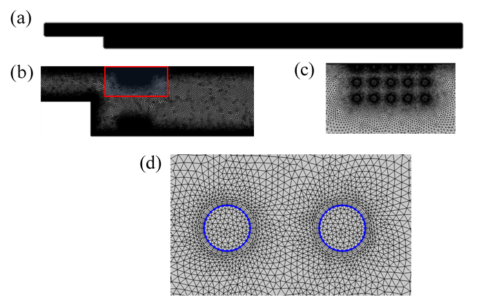
The physical system under consideration is shown in Figure 1. It consists of a two-dimensional channel with a pair of porous baffles mounted close to the top and bottom walls of the test channel. The channel has an upstream height h (= 0.02m). This height expands by a backward-facing step of height S (= 0.02 m) to a downstream height H (=0.04m). With such geometry, an expansion ratio ER (= H / (H – S)) of 2 is achieved. With a fixed upstream length Lu of 5S, the flow in the inlet section is expected not to be significantly affected by the sudden expansion due to the backward-facing step [11]. The variable downstream length is also Ld. The porous baffles employed in the simulations are square arrays of two-dimensional circular rods. With rods of diameter d and distance between rod centres l, various solid volume fractions ϕ=πd2/(4l2) of the porous baffles are achieved. Consequently, as listed in Table 1, a wide range of specific permeability kp and Darcy number Da (= kp/S2) of the porous baffles (dependent on ϕ) are accomplished. The specific permeability is computed using methodology outlined in reference [24] for flow through a square array of rods. Each porous baffle model is of variable length Lp and constant height Hp. The baffles are installed in such a way that the centre of the most upstream rod is at a variable streamwise location xp behind the step. The baffles are mounted such that the gap between the channel wall and the centre of the most immediate row of rods is of distance g. Apart from the model of Da = 1.35 × 10⁻² with g = l, all other models have a gap g = d.
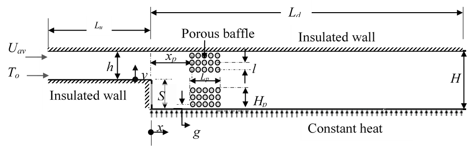
Table 1: Summary of porous baffle solid volume fraction (ϕ) and permeability (kp ) attributes. The symbols l, d and Da (= kp/S2) are respectively the distance between rod centers, diameter, and the Darcy number.
|
l(mm) |
d(mm) |
ϕ |
kp(mm2) |
Da |
|
11.21 |
4.00 |
0.100 |
5.414 |
1.35E-02 |
|
5.39 |
1.55 |
0.065 |
1.660 |
4.15E-03 |
|
2.51 |
1.00 |
0.125 |
0.228 |
5.71E-04 |
|
1.45 |
1.00 |
0.375 |
0.018 |
4.38E-05 |
|
0.63 |
0.50 |
0.500 |
0.001 |
3.52E-06 |
The Cartesian coordinate system is used in this study. As shown in Figure 1, the origin of the streamwise axis x = 0 is positioned at the backward-facing step of the channel. The origin of the wall-normal direction is also located at the bottom wall of the upstream channel.
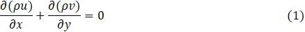
The simulations are conducted under the assumptions of a planar steady-state incompressible Newtonian flow, with negligible body forces. Each porous medium is assumed to be rigid, isotropic and fully saturated with the fluid in the channel. The thermal and fluid flow fields are obtained through the numerical solution of the steady laminar governing equations in the streamwise (x) and wall-normal (y) directions. The relevant governing equations are the following –
Continuity equation:
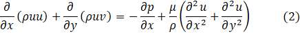
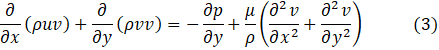
Navier-Stokes equations:
Energy equation:
In Eq. (1) to (4), u and v are the velocity components in the x and y coordinate directions, and μ, ρ, p, T, k, Cp are respectively dynamic viscosity, density, pressure, temperature, thermal conductivity and specific heat capacity. Air is the stated working fluid with properties varying with temperature as given in [23]. Thus, buoyancy effects resulting from temperature differences in the fluid are well accounted for. At the inlet temperature To of 25°C, the dynamic viscosity μ = 1.849× 10⁻⁵ Pa s; density ρ = 1.184 kg m-3, thermal conductivity kf = 0.02551 W m-1 K-1, and specific heat capacity Cp = 1007 J kg-1 K-1 [25]. The Reynolds number Re = ρUav H/μ are specified based on these values. The porous baffles are assumed to be made of Aluminium with properties varying with temperature [23].
For the numerical tests, uniform fluid flow enters into the channel at an average velocity Uav and inlet temperature To. A pressure value is specified at the outlet boundary. Other relevant boundary conditions include: (1) no-slip conditions at solid walls (velocities set at zero), and (2) constant flux (1000 W m-2) applied on the bottom wall of the expanded channel while (3) all other walls are kept at thermally adiabatic conditions.
Based on the physics and boundary conditions specified, the geometric domains were discretized into unstructured triangular and quadrilateral elements (Figure 2). This meshing was done taking into consideration the physics under study, wall boundaries, and corner refinement requirements. Specifically, at the porous medium (cylinder) and wall domains, very fine boundary layer meshes were applied. The domains of conjugate fluid flow and heat transfer were solved using a two-dimensional laminar segregated solver which computes the flow quantities in a sequential manner until convergence is reached. For all the test cases, the residuals of the governing equations were fixed at a tolerance of 10-8
2. 2. Verification of Accuracy of Numerical Model
In order to ensure that the numerical solutions were accurate, mesh independence and validation studies were conducted. For the mesh independence study, a thorough assessment of the sensitivity of the simulation to variations of discretization parameters such as number of elements and mesh sizes was done. This was done by refining the meshes in the domains and boundaries. Results of two sample case studies are shown in Table 2 for typical coupled fluid flow-heat transfer simulations of a backward-facing flow with or without a pair of baffles installed on both top and bottom walls. A wide range of Reynolds number (Re = ρ Uav H / μ = 100, 250, 500, 750, 1000) was tested. Three levels of mesh refinement were evaluated by comparing values of pressure drop (Δp) and average Nusselt number ![]() . The average Nusselt number is a line-averaged parameter computed as follows
. The average Nusselt number is a line-averaged parameter computed as follows

where Nu is the local Nusselt number along the surface of the bottom wall of the channel, defined as:
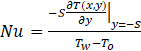
Table 2: Summary of results of mesh independence study for backward-facing step flow with or without a pair of porous baffles. The symbols Nelements, Re, ![]() and Δp are the total number of elements, Reynolds number, averaged Nusselt number and the pressure drop.
and Δp are the total number of elements, Reynolds number, averaged Nusselt number and the pressure drop.
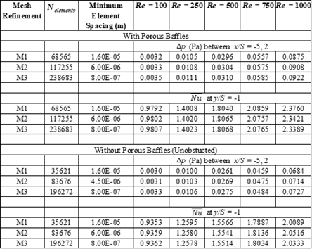
In Eq. (6), Tw is the temperature at y = -S.. As shown in Table 2, the standard deviation in Δp and ![]() values are mostly less than 0.5%. The maximum standard deviation recorded is 1.7% for two
values are mostly less than 0.5%. The maximum standard deviation recorded is 1.7% for two ![]() cases of Re = 1000. This indicates that the results are indeed independent of mesh sizes. From this examination of the mesh independence results, it was determined that a computational mesh with minimum elemental size of 0.0004S, and a maximum elemental size of 0.05S was sufficiently fine to resolve the physics of the flow. This corresponds to mesh refinement level M3 in the mesh independence study. For the entire gamut of test conditions studied, this level of refinement resulted in total number of elements ranging from 83,148 to 733,522, depending on the size and complexity of the computational domain.
cases of Re = 1000. This indicates that the results are indeed independent of mesh sizes. From this examination of the mesh independence results, it was determined that a computational mesh with minimum elemental size of 0.0004S, and a maximum elemental size of 0.05S was sufficiently fine to resolve the physics of the flow. This corresponds to mesh refinement level M3 in the mesh independence study. For the entire gamut of test conditions studied, this level of refinement resulted in total number of elements ranging from 83,148 to 733,522, depending on the size and complexity of the computational domain.
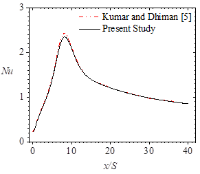
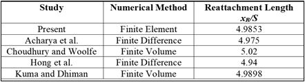
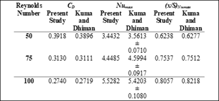
The numerical solution procedure was validated using the results of reattachment lengths of several laminar forced convection backward-facing step flow numerical studies [5], [26] – [28]. The results were found to be within 1% relative deviation. In Figure 3, a representative comparison of local Nusselt number computations of the unobstructed flow is shown to be reasonable. Another round of validation was done for a two-dimensional backward-facing step channel flow with an adiabatic circular cylinder installed at x/S = 0.6 and y/S = 0.6. The summary results of Table 3 also indicate that the peak Nusselt number Numax, total drag coefficient CD and streamwise locations of Numax are within 2% relative deviations.
2.3 Test Parameters
A wide range of conditions were designed in order to test the utility of installing the pair of baffles in the backward-facing flow. The insertion of porous baffles is expected to modify the thermal-fluid flow characteristics. Thus, various porous baffle parameters such as the non-dimensionalized streamwise location (xp/S = 0.5, 1, 2, 3, 4, 5, 6), normalized length (Lp /S = 0.5, 1, 1.5, 2, 2.5), and Darcy number (Da = kp /S2 = 3.52 × 10⁻⁶, 4.38 × 10⁻⁵, 5.71 × 10⁻⁴, 4.15 × 10⁻³, 1.35 × 10⁻²) are tested. The effect of modifying the channel length and the flow regime are also established using a range of downstream channel lengths (Ld/S = 5, 7.5, 15, 30) and a wide range of Reynolds number (Re = ρ Uav H / μ = 100, 250, 500, 750, 1000). As a base group of studies, the test channel is tested without any baffles. This is done for all the range of channel lengths and Reynolds numbers tested in this work.
Table 3: Summary of results of validation studies
The results of the numerical simulations are assessed and characterized using velocity contours and streamlines, temperature contours, local and average Nusselt number computations, a Nusselt number ratio , a pressure drop ratio Δp*, and the performance number PN. The temperature contours were visualized using a normalized temperature parameter

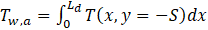
The notations T and To are respectively the local temperature and the inlet temperature To (of 25°C). The line-averaged wall temperature that bottom wall is given by:
TThe average and local Nusselt number computations are expressed in Eq (5) and (6) respectively. The Nusselt number ratio ![]() is computed from the following relation:
is computed from the following relation:

Here, ![]() is the average Nusselt number, and
is the average Nusselt number, and ![]() b is the average Nusselt number of the equivalent unobstructed flow. The pressure drop ratio is also defined as:
b is the average Nusselt number of the equivalent unobstructed flow. The pressure drop ratio is also defined as:

where Δp and Δpb are respectively the pressure drops per unit length between x/S = -5 and Ld/S with or without porous baffles. The performance number PN is defined as:

3. Results and Discussion
In this section, numerical results stemming from varying parameters are presented and described. To evaluate the parameters tested in a logical fashion, the effect of the non-dimensionalized streamwise location of the porous baffle is assessed firstly. This is followed by a study of the effects of modifying the length and Darcy number of the porous baffles. Furthermore, the effects of the length of the downstream length of the test channels are described. As the effects of Reynolds number of the flow are integral, they are discussed as part of the other effects.
3. 1. Effects of Porous Baffle Location
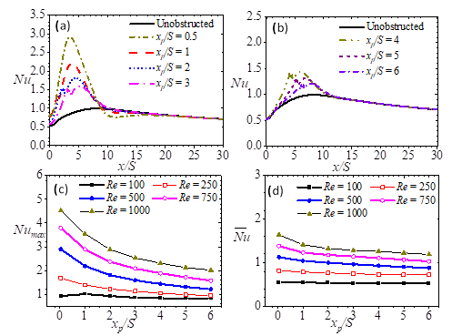
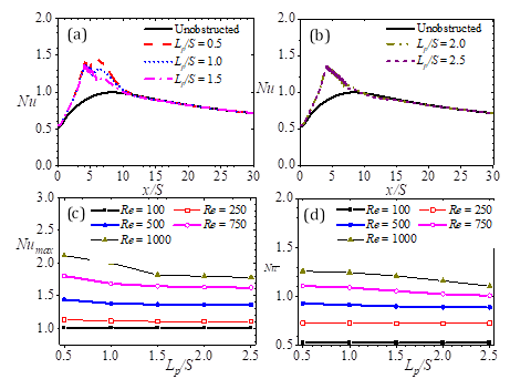
The effects of porous baffle location are demonstrated using test results for which normalized porous baffle length and porous baffle Darcy number are Lp /S = 0.5 and Da = 5.71 × 10⁻⁴ respectively, and the downstream length of the channel is maintained at Ld/S = 15. The local Nusselt profiles in Figure 4 (a, b) are those for which Re = 500. However, the general trend observed in the numerical results is that the insertion of the pair of porous baffles generally leads to a marked improvement in the convective heat transfer from the bottom wall of the test channel for other Reynolds numbers (Figure 4 c, d). The local maximum Nusselt number Numax is located behind the porous baffles, and is highest for the porous baffles that are closest to the backward-facing step. Moving the baffles further downstream generally results in a bimodal distribution along with a decline in Nusselt numbers. Consequently, by relocating the baffles from xp/S = 1 to xp/S = 6, Numax is cut by up to 32%. Additionally, the average Nusselt numbers are also reduced by up to 15%. As such reduction yields Nusselt values that are comparable with the case of an unobstructed flow, it is obvious then that the location of the porous baffle can counter gains recorded by the use porous baffles.
 . Each of these profiles are of downstream length Ld/S = 15. Those with baffles have baffles of normalized length Lp /S is 0.5, porous baffle Darcy number Da is 5.71 × 10⁻⁴, and the downstream length of the channel is maintained at Ld/S = 15.
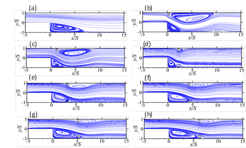
Streamlines of a portion of the channel flow, and for the cases presented in Figure 4 (a, b) are shown in Figure 5. They provide some further insight into the phenomena observed in the foregoing paragraph. They demonstrate that the placement of a pair of porous baffles close to the top and bottom walls leads to two remarkable developments in the flow. The first is a shrinkage of the recirculation region behind the step, while the second is the evolution of a recirculation region trailing the top porous baffle. The characteristically low velocities resulting from the recirculation region behind the step appears to dampen the convection of heat from the bottom wall of the channel. This recirculation region widens as the porous baffles are moved further down downstream, hence resulting in a monotonic reduction in Numax and ![]() . The insertion of the porous baffles serves to contract the recirculation region behind the step. This helps to enhance the heat transfer from the bottom wall. It may also be noted that a widening of the recirculation region on the top wall results in a diversion of flow to the bottom wall. Consequently, the local Nusselt numbers around the porous baffle region are drastically improved if there is a shrunken recirculation region at the bottom wall, as well as an extensive recirculation region on the top wall. The result is the high (up to 71% more than the case of unobstructed flow) Nusselt numbers reached by baffles at xp/l = 0.5. As shown in Figures 5 and 6, this improvement is only undermined locally and globally by the location of the porous baffles further downstream, where the streamwise length of the recirculation region on the bottom wall is increased, and that of the upper wall is reduced.
. The insertion of the porous baffles serves to contract the recirculation region behind the step. This helps to enhance the heat transfer from the bottom wall. It may also be noted that a widening of the recirculation region on the top wall results in a diversion of flow to the bottom wall. Consequently, the local Nusselt numbers around the porous baffle region are drastically improved if there is a shrunken recirculation region at the bottom wall, as well as an extensive recirculation region on the top wall. The result is the high (up to 71% more than the case of unobstructed flow) Nusselt numbers reached by baffles at xp/l = 0.5. As shown in Figures 5 and 6, this improvement is only undermined locally and globally by the location of the porous baffles further downstream, where the streamwise length of the recirculation region on the bottom wall is increased, and that of the upper wall is reduced.
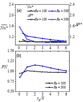
It should also be noted that the utility of the enhanced heat transfer due to the placement of the porous baffles is dependent on the increment of pressure drop incurred. An increase in the extent of the recirculating region on the upper wall represents an increment in the limited free path zone on the upper wall, which in turn increases the pressure drop Δp* incurred. Thus, as shown in Figure 6, the best performance number (1.15) is reached when the baffles are located at a streamwise location that yields bottom wall and top wall recirculation zones of the most optimal combinations of minimum recirculation extents (i.e. at xp/S = 2). This occurs at Re = 1000.
3.2 Effects of Porous Baffle Length
The effects of porous baffle length are demonstrated using test results for which porous baffle Darcy number is Da = 5.71 × 10⁻⁴, the downstream length of the channel maintained at Ld/S = 15, the baffles located at xp /S = 4 and the normalized porous baffle length Lp /S modified from 0.5 to 2.5. Excerpts of the flow simulations are shown in Figures 7 to 9.
 , pressure drop ratio Δp*, and (b) performance number PN distributions for various baffle locations. These normalized porous baffle length Lp /S is 0.5, and the porous baffle Darcy number Da is 5.71 × 10⁻⁴. The channel downstream length Ld/S = 15 and Reynolds numbers Re = 100, 500.
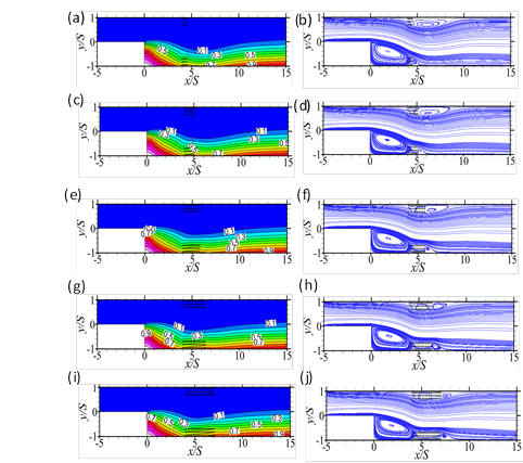
The iso-contours and streamlines in Figure 7 show that the porous baffle length is a significant determinant in predicting the level of convection further downstream of the expanded channel. The iso-contours of the normalized temperature T* in particular indicates that downstream of the porous baffle, the thickness of the layer of fluid of high temperature on the bottom wall increases with the length of porous baffle. The implication is that the thermal boundary layer thickness associated with the heated wall grows as the baffle length is increased. The reason for such an occurrence may be gleaned from the streamlines in Figure 7. The streamlines show that a secondary recirculation region behind the porous baffle and close to the bottom wall, is apparent in the flow, and it increases with baffle length. While the growth in length of that recirculating region is only ~0.5S, it is still significant (~ 50%); and the consequence of such a region of relatively low velocity region is a limited but suppressed convection of heat from the hot bottom wall. In Figure 8, it is clear that as the porous baffle length increases, both peaks of the bimodal local Nusselt distribution reduces. The averaged Nusselt numbers show that while the local changes in heat transfer due to the increment in porous baffle length are significant, the global effects are only marginal. Thus, as indicated in Figure 8(c), the reduction averaged Nusselt numbers become only discernible at Reynolds number above 250, and even so, with a change of no more than 8%.
 .
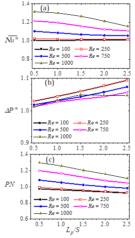
.In Figure 9, the Nusselt numbers ![]() , pressure drops and the heat transfer enhancement to pressure drop increment assessments of the baffled flows are compared with the equivalent unobstructed flows. These are done using the Nusselt number ratio
, pressure drops and the heat transfer enhancement to pressure drop increment assessments of the baffled flows are compared with the equivalent unobstructed flows. These are done using the Nusselt number ratio ![]() , pressure drop ratio Δp*, and performance number PN. The plots in Figure 9(a) show that the best improvements in heat transfer are attained when the porous baffle lengths are half the size of the step height. The plots on the other hand, indicate that there is no significant additional heat transfer benefit to utilizing those baffles in the flow if the baffles are of length Lp /S > 2. This latter observation is because at Lp /S > 2, irrespective of the Reynolds number of the flow, the Nusselt numbers attained are essentially those of an unobstructed flow. With respect to pressure drops, Figure 9(b) shows that compared to the unobstructed flows, the pressure drops incurred in the baffled flows generally increase with porous baffle length (as expected). The exception however occurs at Reynolds number Re = 1000. At that Reynolds number, the pressure drops of the baffled flows do not increase any more than the unobstructed flow at Lp /S > 1.5. When the porous baffle length increases, the pressure drop increases, and the Nusselt number ratio decreases. Consequently, the performance number drops monotonically. In Figure 9(c), this drop in performance number is up to 15% as the baffle length Lp/S is increased from 0.5 to 2.5. In summary, the foregoing results show that in order to reap the best effects of heat transfer enhancement with minimal differential power requirement, it is best to have a compact porous baffle in the flow, preferably one that has a length that is just half the size of the step height.
, pressure drop ratio Δp*, and performance number PN. The plots in Figure 9(a) show that the best improvements in heat transfer are attained when the porous baffle lengths are half the size of the step height. The plots on the other hand, indicate that there is no significant additional heat transfer benefit to utilizing those baffles in the flow if the baffles are of length Lp /S > 2. This latter observation is because at Lp /S > 2, irrespective of the Reynolds number of the flow, the Nusselt numbers attained are essentially those of an unobstructed flow. With respect to pressure drops, Figure 9(b) shows that compared to the unobstructed flows, the pressure drops incurred in the baffled flows generally increase with porous baffle length (as expected). The exception however occurs at Reynolds number Re = 1000. At that Reynolds number, the pressure drops of the baffled flows do not increase any more than the unobstructed flow at Lp /S > 1.5. When the porous baffle length increases, the pressure drop increases, and the Nusselt number ratio decreases. Consequently, the performance number drops monotonically. In Figure 9(c), this drop in performance number is up to 15% as the baffle length Lp/S is increased from 0.5 to 2.5. In summary, the foregoing results show that in order to reap the best effects of heat transfer enhancement with minimal differential power requirement, it is best to have a compact porous baffle in the flow, preferably one that has a length that is just half the size of the step height.
 , (b) pressure drop ratio Δp*, and (c) performance number PN distributions for porous baffles of different length Lp /S. The baffles are located at xp /S = 4 and are of Darcy number Da = 5.71 × 10⁻⁴.
3.3 Effects of Porous Baffle Darcy Number
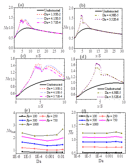
The effects of the permeability of the porous baffles are examined using baffles of Da ranging from 10-6 to 10-2, achieved by means of varied dimensions (see Table 1). The results shown in Figures 10 and 11, are those for which the baffle length and streamwise location are respectively maintained at Lp /S = 0.5 and xp /S = 4. In Figure 10 (a - d), the local Nusselt distributions show the plots for a selected case at Re = 500. The data shows (as noted previously) that the mounting of porous baffles results in a bimodal distribution. In Figure 10 (c, d), the distinctions between the various porous baffles are magnified by showing the zoomed-in plots of Figure 10 (a, b) close to the step. The plots reveal that the upstream peak values fall within the actual location of the porous baffle. The downstream peak values on the other hand, are located downstream of the porous baffle. They are more predictable compared to the upstream peak values as they appear to be a direct function of the solid volume fraction of the porous baffles. The downstream peak values also suggest that the higher the solid volume fraction, the lower the Nusselt values. Such a trend is expected due to blockage of flow created by the solid rods in the flow. Regardless, it must be emphasized that the Nusselt distributions in Figure 10 (e) however show that the overall peak values are affected mainly by the Reynolds number of the flow, and in part, the Darcy number and the mode of arrangement of the porous baffle rods. An increase in Reynolds number from 100 to 1000 results in a non-monotonic increment in peak Nusselt number for baffles, irrespective of the solid volume fraction. While the effect of Darcy number appears to be significant in dictating the value of the peak Nusselt Number (Figure 10e), the average Nusselt numbers (Figure 10f) indicate that such effects are only local, so that local porous medium permeability is not a factor in determining the global Nusselt number.
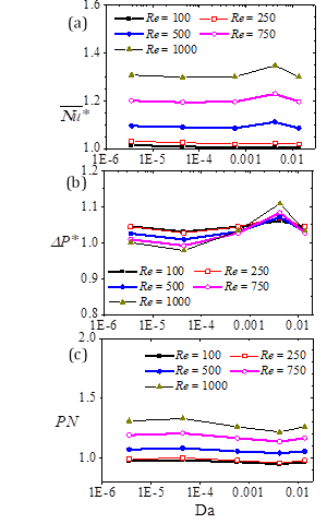
Figure 11 demonstrates that the comparative ratios of Nusselt number, pressure drop, and the performance numbers for the baffled and unobstructed flows are complicated. The results show that the ratio of the baffled flow Nusselt number to that of the unobstructed flow (Figure 11a) appears to be essentially constant as the Darcy number is increased from 3.52 × 10⁻⁶ to 1.35 × 10⁻². However, the ratio increases substantially for Da > 10-3and Re > 500. The reason for the marked increases may be attributed to the channeling of relatively high-speed flow through the path between the lower porous baffles as the porous baffle is more permeable. Any diversion of flow to the heated bottom wall leads to a significant convection of heat away from the heated bottom wall, and thus improved Nusselt numbers. The changes of the pressure ratio (Figure 11b) with Da are non-monotonic, and therefore it is no surprise that the performance numbers are expectedly non-monotonic (Figure 11c). The best performance number (1.33) is obtained with porous baffles of Da = 4.38 × 10⁻⁵. This observation concurs with the conclusion of Zhao [20] that even low-permeable baffles could augment heat transfer at the expense of little pressure drop.
 .
.3.4 Effects of Channel Length
Early on, it was recognized that the downstream (expanded) channel length Ld is a critical factor for the determination of global heat transfer gains. Thus, it is important to determine the effects of variant channel length as well as the optimal compact downstream length for which heat transfer enhancements could be reached at minimal pressure differential cost. This is done for 5 < Lp /S < 30 for test cases with baffles of length Lp /S = 0.5 and Da = 4.38 × 10⁻⁵. The baffles are located at xp /S = 4. In each of the cases considered, the exit pressure boundary condition is kept constant. The results are summarized in Figure 12. Evaluations of Nusselt number ratio ![]() , pressure drop ratio Δp*, and performance number PN show that the lower the Reynolds number the marginal the changes in
, pressure drop ratio Δp*, and performance number PN show that the lower the Reynolds number the marginal the changes in ![]() ;The decline in pressure drops are also generally small (no more than 7%). The implication then is that the use of a pair of porous baffles is most advantageous in compact systems and at high Reynolds number. For such arrangements, the gain in heat transfer compared to an unobstructed channel can be as high as 200%. A PN of 188% is also possible. Such a PN indicates that for the same pump differential pressure, the average convection to conduction heat transfer is up to 88% better when a pair of similar porous baffles are used. Zhao [20] reported that for a backward facing step flow with constant bottom wall temperature conditions at the expanded channel, a PN of > 140% is reached when a porous baffle is mounted on the bottom wall in a channel of Ld /S = 30, and at Re = 100. On the other hand, multiple baffles are prohibitive when the Reynolds number is low (e.g. Re < 500). This is because at such Reynolds numbers, heat transfer and pressure drop increments are comparable with that of an unobstructed flow.
;The decline in pressure drops are also generally small (no more than 7%). The implication then is that the use of a pair of porous baffles is most advantageous in compact systems and at high Reynolds number. For such arrangements, the gain in heat transfer compared to an unobstructed channel can be as high as 200%. A PN of 188% is also possible. Such a PN indicates that for the same pump differential pressure, the average convection to conduction heat transfer is up to 88% better when a pair of similar porous baffles are used. Zhao [20] reported that for a backward facing step flow with constant bottom wall temperature conditions at the expanded channel, a PN of > 140% is reached when a porous baffle is mounted on the bottom wall in a channel of Ld /S = 30, and at Re = 100. On the other hand, multiple baffles are prohibitive when the Reynolds number is low (e.g. Re < 500). This is because at such Reynolds numbers, heat transfer and pressure drop increments are comparable with that of an unobstructed flow.
 , (b) pressure drop ratio Δp*, and (c) performance number PN for porous baffles of different Darcy numbers. The baffles are located at xp /S = 4 and are of length Lp /S.= 0.5
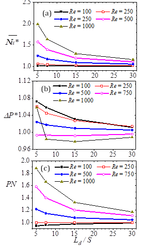 , (b) pressure drop ratio Δp*, and (c) performance number PN for porous baffles of different normalized downstream channel length (Ld /S). The baffles are of length Lp /S.= 0.5 and Da = 4.38 × 10⁻⁵, and located at xp /S = 4.
Conclusion
In this work, a numerical simulation of the coupled fluid flow and heat transfer phenomena in a planar backward-facing step channel has been presented. The Reynolds number, Re (= 100, 250, 500, 750, 1000), normalized streamwise porous matrix location xp/S (= 0.5, 1, 2, 3, 4, 5, 6), normalized porous block length Lp/S (= 0.5, 1, 1.5, 2, 2.5), normalized channel downstream length Ld /S (= 5, 7.5, 15, 30), and Darcy Number, Da (= 3.52 10-6, 4.38 10-5, 5.71 10-4, 4.15 10-3, 1.35 10-2) are tested. From the computations, it is conclusive that the placement of a pair of porous baffles close to the top and bottom walls leads to a shrinkage of the recirculation region behind the step, and the evolution of a recirculation region trailing the top porous baffle. The relative proportions of these recirculation regions bear a significant influence on the heat transfer that is enhanced per pressure drop cost. Compared to the case of an unobstructed channel, the installation of porous baffles on both channel walls can generate 200% improvement in heat transfer. However, the best gains in heat transfer per increment in pressure drop are obtained at high Reynolds number applications (Re > 500), and for compact channel lengths. For such cases also, the porous baffles should be about half the size of the step height. Furthermore, an optimal streamwise location would be twice the step height downstream of the backward-facing step. While the best performance number is obtained with porous baffles of Darcy number Da = 4.38 × 10⁻⁵, the present results show that for a pair of porous baffle installations, the local porous medium permeability is not a factor in determining the global Nusselt number. This work shows that for the same pump differential pressure, the average convection to conduction heat transfer is up to 88% better when a pair of similar porous baffles are used compared to the case of an unobstructed flow.
References
[1] Abu-Hijleh B. Convection heat transfer from a laminar flow over a 2-d backward facing step with asymmetric and orthotropic porous floor segments. Numer. Heat Transf. A. 1997; 31: 325-35. View Article
[2] Chen L, Asai NT, Xi G, Liu T. A review of backward-facing step (bfs) flow mechanisms, heat transfer and control. Therm. Sci. Eng. Prog. 2018; 6: 194-216. View Article
[3] Salman S, Abu Talib AR, Saadon S, Hameed Sultan MT. Hybrid nanofluid flow and heat transfer over backward and forward steps: a review. Powder Technol. 2020; 363: 448-72. View Article
[4] Tsay YL, Chang TS, Cheng JC. Heat transfer enhancement of backward-facing step flow in a channel by using baffle installation on the channel wall. Acta Mech.2005; 174: 63–76. View Article
[5] Kumar A, Dhiman AK. Effect of a circular cylinder on separated forced convection at a backward-facing step. Int. J. Therm. Sci. 2012; 52: 176-85. View Article
[6] Guo ZY, Li DY, Liang XG. Thermal effect on the recirculation zone in sudden-expansion gas flows. Int. J. Heat Mass Transfer. 1996; 39: 2619-24. View Article
[7] Uruba V, Jonas P, Mazur O. Control of a channel-flow behind a backward-facing step by suction/blowing. Int. J. Heat Fluid Flow. 2007; 28: 665-72. View Article
[8] Glezer A, Amitay M. Synthetic jets. Ann. Rev. Fluid Mech. 2002; 34:503-29. View Article
[9] Cattafesta LN, Shplak M. Actuators for active flow control. Ann. Rev. Fluid Mech. 2011; 43: 247-72. View Article
[10] Lin JC. Review of research on low-profile vortex generators to control boundary-layer separation. Prog. Aero. Sci. 2002; 38: 389-420. View Article
[11] Nie JH, Chen YT, Hsieh HT. Effects of a baffle on separated convection flow adjacent to backward-facing step. Int. J. Therm. Sci. 2009; 48: 618-25. View Article
[12] Chen CK, Yen TS, Yang, YT. Lattice Boltzmann method simulation of a cylinder in the backward-facing step flow with the field synergy principle. Int. J. Therm. Sci. 2006; 45(10): 982-9. View Article
[13] Ahmed H, Kherbeet AS, Ahmed MI, Salman BH. Heat transfer enhancement of micro-scale backward-facing step channel by using turbulators. Int. J. Heat Mass Tran. 2018; 126: 963-73. View Article
[14] Protim M, Randive PR, Pati S. Hydrothermal performance and entropy generation analysis for mixed convective flows over a backward facing step channel with baffle. Int. J. Heat Mass Transfer. 2018; 125: 525-42. View Article
[15] Cheng JC, Tsay YL. Effects of solid and slotted baffles on the convection characteristics of backward-facing step flow in a channel. Int. J. Heat Mass Transfer. 2006; 42: 843–52. View Article
[16] Mohammed HA, Alawi O, Wahid MA. Mixed convective nanofluid flow in a channel having backward-facing step with a baffle. Powder Technol. 2015; 275: 329-43. View Article
[17] Ma Y, Mohebbi R, Rashidi MM, Yang Z, Fang Y. Baffle and geometry effects on nanofluid forced convection over forward- and backward-facing steps channel by means of lattice Boltzmann method. Physica A Stat. Mech. Appl. 2020; 554:124696. View Article
[18] Li C, Zhai J, Chen S, Hu Z. Enhanced heat transfer and flow analysis in a backward-facing step using a porous baffle. J. Therm. Anal. Calorim.2020; 141:1919–32. View Article
[19] Martin AR, Saltiel C, Shyy W. Heat transfer enhancement with porous inserts in recirculating flows. J. Heat Transfer. 1998; 120(2): 458-67. View Article
[20] Zhao Z. Numerical modeling and simulation of heat transfer and fluid flow in a two-dimensional sudden expansion model using porous insert behind that. J. Therm. Anal. Calorim.2020; 141:1933-42. View Article
[21] Chen XB, Yu P, Winoto SH, Low HT. Forced convection over a backward-facing step with a porous floor segment. Numer. Heat Transf. A. 2008; 53: 1211-30. View Article
[22] Selimefendigila F, Öztop HF. Forced convection and thermal predictions of pulsating nanofluid flow over a backward facing step with a corrugated bottom wall. Int. J. Heat Mass Transfer.2017; 110: 231-47. View Article
[23] COMSOL Multiphysics. v 5.5., www.comsol.com., Stockholm, Sweden.: COMSOL AB.
[24] Arthur J. PIV study of flow through and over porous media at the onset of inertia. Adv Water Resour. 2021; 146: 103793. View Article
[25] Çengel YA, Turner RH, Cimbala JM, Kanoglu M. Fundamentals of thermal-fluid sciences. 2nd ed. New York: McGraw-Hill; 2008.
[26] Acharya S, Dixit, G, Hou Q. Laminar mixed convection in a vertical channel with a backstep: a benchmark study, ASME HTD 258 1993; 11e20.
[27] Choudhury D, Woolfe AE. Computation of laminar forced and mixed convection in a heated vertical duct with a step, ASME HTD 258 1993; 29e36.
[28] Hong B, Armaly BF, Chen TS. Mixed convection in a laminar, vertical, backward-facing step flow: solution to a benchmark problem, ASME HTD 258 1993 57e62.