Journal of Fluid Flow, Heat and Mass Transfer (JFFHMT)
ISSN: 2368-6111

Volume 8 - Year 2021 - Pages 217-225
DOI: 10.11159/jffhmt.2021.023
Numerical Analysis of Mixing Performance of a Novel ‘Y-U’ Split and Recombine Micromixer
Md. Readul Mahmud
Independent University, Bangladesh, Department of Physical Sciences
Plot 16 Block B, Aftabuddin Ahmed Road Bashundhara R/A, Dhaka-1229, Bangladesh
mahmud.readul@iub.edu.bd
Abstract - This work presents a design of a new micromixer named ‘Y-U’ based on the split and recombine (SAR) principle. Five mixers are constructed varying a parameter, vertical cylindrical connector height H (Y-UH), starting from 0 mm to 0.8 mm. Numerical analysis is carried out at Reynolds numbers ranging from 1 to 50 using FLUENT 15 for the purpose of optimization. A well-known SAR mixer, namely ‘H’ is also studied in order to validate the numerical model. Proposed Y-U mixers offer better mixing performance than H mixer regardless of Reynolds numbers. The Y-U mixers show more than 90% efficiency at low Reynolds numbers and efficiency is about 60% for Reynolds numbers from 10 to 50. Mixing efficiency depends on the vertical cylindrical connector height (H); efficiency and pressure drop increases with the increase of vertical cylindrical height. Y-U 0.8 mm (H = 0.8 mm) shows better maximum efficiency compare to all examined mixers. In addition, the mixing cost is independent of vertical cylindrical height.
Keywords: CFD, Micromixing, Micromixer, Mixing cost, SAR.
© Copyright 2021 Authors - This is an Open Access article published under the Creative Commons Attribution License terms Creative Commons Attribution License terms. Unrestricted use, distribution, and reproduction in any medium are permitted, provided the original work is properly cited.
Date Received: 2021-03-10
Date Accepted: 2021-05-29
Date Published: 2021-08-03
1. Introduction
The microfluidic technique is a discipline which has gained widespread attention in recent years due to its various use and rapid development [1]. Micromixer is a device that mixes fluids regardless of their properties and nature such as density, viscosity, surface tension, etc. on a micro-scale. Micromixers and microreactors are used in a wide range of chemical reactions, biochemical reactions, drug development and delivery, medical diagnosis, chemical synthesis, and food industries [2], [3]. The main advantage of micromixers over macro batch reactors or mixers are rapid analysis, portability, higher control, low cost, spending fewer amounts of costly reagents, and high safety in case of an explosion in case of explosive chemical reactions [4]. Some other benefits of using micromixers are reproducible environment, benefit various biological applications from nucleic acid and protein analysis to drug development and drug delivery [5]. Generally, micromixers operate at low Reynolds number (Re), hence the flow is predominantly laminar, and the mixing process relies on molecular diffusion, which requires a considerable channel length and time to achieve good mixing performance [6]. To overcome these shortcomings two distinct types of mixers are introduced, namely active and passive. Active mixers use various external energy sources (acoustic field, periodic pressure field, electric field, temperature field, magnetic field, etc.) to enhance the mixing process [7], [8]. On the other hand, passive mixers have no active element but use special geometrical features, and channel shape and size to achieve good performance. Generally, active micromixers have higher mixing efficiency compare to passive ones because active mixers require an extra energy source, are difficult to integrate into the microfluidic system, and complex fabrication [9]. Whereas passive mixers use a grooved surface, a herringbone wall, obstacles to the channel walls, baffles inside the channel, split and recombine (SAR) the fluids to increase mixing in a short time [10].
SAR is a mechanism where fluids are repeatedly split and recombine, as a consequence various multi-lamination of fluids are created which significantly increases the mixing index [11]. SAR mixers using different principles are designed and studied by many authors. Unbalance SAR mixer is proposed by authors [12], [13]; SAR mixer with obstacle or baffle is studied by authors [14], [15]; SAR mixer using curved channel designed by authors [16]-[19]; and SAR mixer designed with different shaped mixing unit [11], [20], [21] was studied. .
The use of computational fluid dynamics (CFD) is increasing rapidly to study the fluid dynamic features thanks to the rapid development of computer memory and processing time. Numerical simulation allows calculation of various parameters (pressure-drop, velocity, efficiency, species concentration, etc.) and detailed visualization of the mixing process as well as the associated flow patterns such as streamlines, vortex formation, velocity vector, etc. [9]. CFD has become an economic, time-saving, and effective method of investigating the reactive flow and of exploring new geometries of microreactors through visualizing the mixing and reaction process [6]. Therefore lots of researchers are using CFD to design and analyze novel micromixers [22], [23].
In this work, a new passive micromixer is designed on the SAR principle and the mixing performance is computed numerically using commercial software FLUENT 15. The proposed ‘Y-UH’ mixer is made up of four elements, and each element is composed of a Y-shaped and U-shaped channel. Each channel is connected with a vertical cylindrical channel (vertical connector H). The length of the cylindrical connector (H) is varied starting from 0 mm to 0.8 mm; increased 0.2 mm in each step. The mixing performance of the five mixers is analyzed with varying vertical cylindrical channel lengths (H) and Reynolds numbers (Re). A SAR ‘H’ mixer is also analyzed as a point of reference. The numerical simulation was carried out for the Reynolds numbers ranging from 1 to 50 to propose the best-performing mixer.
2. Micromixer Design
A new 3D passive micromixer namely ‘Y-U’ is designed taking the advantage of split and recombine principle as shown in Figure 1. As the name suggests, each element of the mixer is composed of one ‘Y’ and one ‘U’ shaped channel segment. The ‘Y-U’ mixer has four identical elements, where one ‘Y’ and one ‘U’ segment constitutes one element. The radius of inlets and outlet cylindrical sections is 0.4 mm and 0.6 mm, respectively. The depth of the mixers is always kept constant at 0.4 mm.
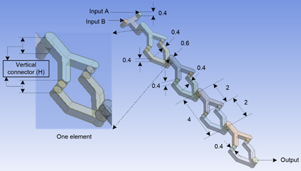
Each element as well as every ‘Y’ and ‘U’ segment are connected by a vertical cylindrical connector (H) as shown in Figure 1. The length of the cylindrical connector (H) is varied starting from 0 mm to 0.8 mm; increased 0.2 mm each step. Hence, there are five ‘Y-U’ mixers with different vertical connector height which are represent by Y-U0 mm (H = 0 mm), Y-U0.2 mm (H = 0.2 mm), Y-U0.4 mm (H = 0.4 mm), Y-U0.6 mm (H = 0.6 mm) and Y-U0.8 mm (H = 0.8 mm).
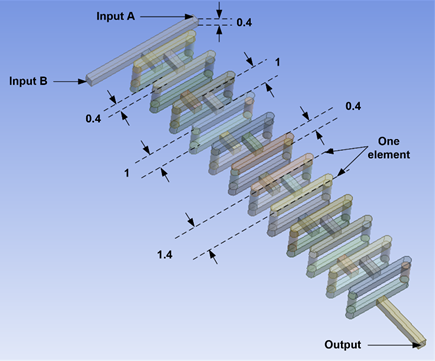
The ‘H’ mixer is designed and experimentally examined the efficiency for a low Reynolds number range, by M. Nimafar et al. [24]. The H-micromixer geometry consists of two parts: the straight channel and the H-segment which indicates one element as shown in Figure 2. The width and height of inputs and output are 0.4 mm, and the length of one element is 1.4 mm. H mixer consists of 12 identical elements and the total axial length of the H mixer is 20 mm.
3. Numerical Method
The flow characteristics and mixing performance of the mixer were analyzed by Ansys FLUENT 15, using a finite volume method. Two fluids enter into two inputs and mixed fluid exit the mixer by output. In the present study, both fluids have the physical properties of water. The density, viscosity, and diffusions constant of the water is 1000 kg/m3, 0.001 Pa s and 1×10⁻⁹ m2/s, respectively. The Reynolds numbers, which are an important parameter for fluid flow, are calculated by the following equation [25].

In equation (1), ρ is the fluid density, µ is the dynamic viscosity, and v is the fluid velocity, evaluated at the rectangular channel. The characteristics length d equals 0.4 mm, which is the minimum dimension of the mixers [26].
The flow of steady, incompressible, laminar, and Newtonian liquid in microchannels was considered. Ansys FLUENT 15 employed a coupled solver and finite volume technique to discretize continuity, Navier–Stokes, and species convection-diffusion equations [16], [27].


Where V denotes fluid velocity vector, ρ is the fluid density, and μ represents the dynamic viscosity of the fluid; P equals pressure, C denotes the mass concentration of the species and D represents the coefficient of diffusion. In this work, the diffusion constant is considered as 1× 10⁻⁹m2/s. The mass concentration of the two species in inlet 1 and inlet 2 was set as 0 and 1, respectively and uniform mixing was achieved when the mass intensity of the two species reached the value of 0.5. The inlets and outlet were set as velocity inlet and pressure outlet, respectively, and No-slip boundary conditions were considered. The integration of discrete equations coupled in the pressure−velocity formulation was realized with the implicit algorithm SIMPLEC. QUICK scheme (for momentum and species) and the PRESTO (pressure staggering option) scheme (for pressure) was also employed in the simulation [6]. To ascertain the mixing performance as a standard criterion for evaluation of the mixing process, the following equations are used [28].
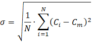
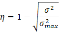
In equations (5) and (6), σ denotes the standard deviation of the mass fraction at a cross-sectional plane, N is the number of data points in that cross-sectional plane, Ci is the mass fraction of a point i, Cm is the optimal mass fraction and σmax is the maximum variance of the mass fraction over the data range; η is the mixing efficiency which varies from zero to one. Zero represents unmixed and one represents perfectly mixed species, efficiency between 80% and 100% is acceptable for mixing process applications [29].
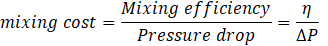
Increasing the Reynolds numbers always increases the pressure drop inside the micromixer. Therefore, the ratio of mixing efficiency to pressure drop ![]() can be used to reveal the ‘cost’ of mixing. A high value of mixing cost indicates an efficient micromixer [28], [30].
can be used to reveal the ‘cost’ of mixing. A high value of mixing cost indicates an efficient micromixer [28], [30].
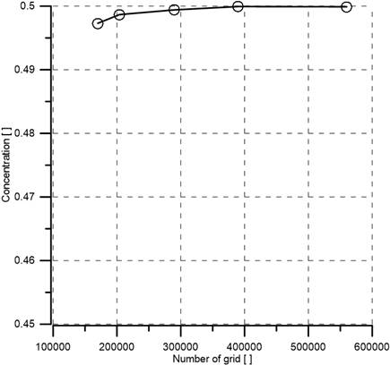
In numerical analysis, a high-quality mesh model is critical to the accuracy of the results [18]. The mesh independence test is very important to ensure that numerical data do not depend on grid size and shape [31]. Hence, structured tetrahedral cells were used for the numerical test as recommended by authors [32]. Path conforming algorithm was employed with no suppression to generate tetrahedral grid systems. Six different grids systems in which the number of nodes varied from 1.7× 10⁵ to 5.6× 10⁵ were tested for Y-U0.6 mm (H = 0.6 mm) mixer. The spices concentration (water) for different grid numbers is shown in Figure 3 and there is a narrow difference between the concentrations by increasing the number of grids. As illustrated in Figure 3 the concentration at Re=10, there are very little variation which is less than 1%. Therefore, grid system of nodes number of 2.85× 10⁵ was selected for the simulation to reduce numerical cost and analysis time. Similarly, grid independence test for the rest of four Y-U mixers was also performed, and 2.72× 10⁵, 2.76×10⁵, 2.89×10⁵, and 2.94× 10⁵ nodes were selected for Y-U0 mm, Y-U0.2 mm, Y-U0.4 mm and Y-U0.8 mm mixers, respectively.
4. Result and Discussion
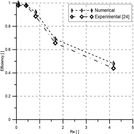
To verify the numerical method, a SAR ‘H’ mixer [24] was designed and numerical simulations were performed for 0.083≤Re≤4.166. The published experimental data and numerical simulation data of the present study is compared for the H mixer after 20 mm and are shown in Figure 4. There is a good agreement between numerical simulation results and experimental data; the variation is less than 10%. Grid of 5.46×10⁵ nodes were chosen for the numerical simulation after the grid independence test. The observed error may be attributed to the structural conditions of the micromixer, such as not-perfectly smooth walls and minor dimensional inconsistency. It is also important to mentions that it is always challenging to exactly replicate experimental data for any micromixer by numerical simulation.
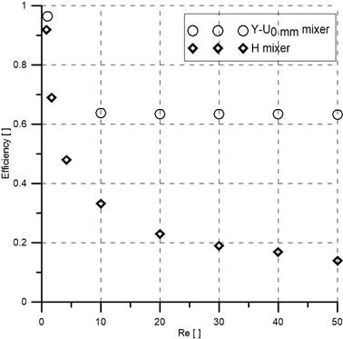
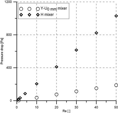
Now the comparison of numerical mixing efficiency and pressure drop between H mixer and Y-U0 mm mixer is presented in Figure 5. It is evident that the efficiency of the Y-U0 mm mixer is higher and the pressure drop is lower than the H mixer at all examined Reynolds numbers. Y-U0 mm mixer shows more than three times efficiency than H mixer but yields five times less pressure drop than H mixer at Re=50. Hence is certain that the proposed Y-U0 mm mixer is a better SAR mixer compare to the H mixer at all examined Reynolds numbers. Therefore, only Y-U mixers are studied for further analysis.
The overall mixing performance of all mixers with different vertical connector height H (0 mm to 0.8 mm) was analyzed. The distributions of the concentration of water inside the mixers at a Reynolds number of 1 and 30 are shown in Figure 6. There is a small variation in the concentration of water for all mixers at Re = 1 and Re = 30. There is a noticeable change in water concentration when Reynolds members increase from 1 to 30, which indicates at higher Reynolds numbers (Re=30) efficiency will decrease compare to low Reynolds numbers (Re=1).
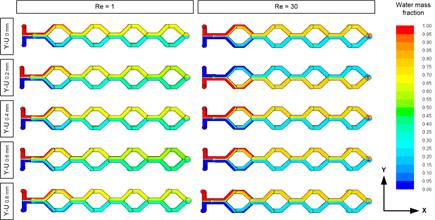
Figure 7 shows the variation curves of mixing efficiency (η) for Y-UH micromixers changing the vertical cylindrical connecting height (H) under different Re. It can be found that all mixers show the same trend at Reynolds numbers ranging from 1 to 30. At low Reynolds numbers (Re=1), the liquid flows at a low speed in the mixer, and the mixing mechanism is mainly diffusion. Hence good mixing is achieved due to longer residence time, which is about 90% for all mixers. As the Re value increases, the flow rate in the mixer increases, and the time for the diffusion of chemical molecules decreases, resulting in a decrease in the mixing efficiency. The mixing index does not changes for Re≥10, because the influence of the secondary flow is not strong enough to compensate for the shorter mixing time due to the increase of flow rate (as shown in Figure 8). It is evident that mixing efficiency depends positively on vertical connector height (H). Efficiency increase with the increase of H because of extra path length which gives additional mixing time. All mixers exceed 60% efficiency at higher Reynolds numbers (10≤Re<50). Moreover, Y-U0.8 mm yields the highest efficiency (75%) at 10≤Re<50.
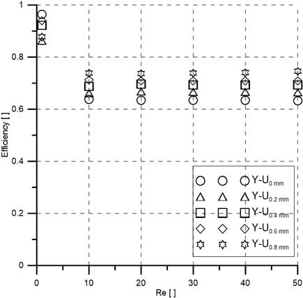
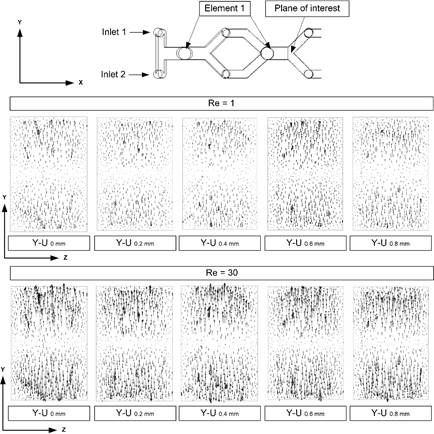
Figure 8 depicts the velocity vector plots on the YZ-plane for five mixers channels at Reynolds numbers of 1, and 30. The flow pattern is almost the same in every cross-section, and the secondary flow is almost negligible. But the efficiency is good because at low Reynolds number (Re=1) fluids have more time to mix. At a Reynolds number of 30, the secondary flow increase for all mixers but not at a significant level. Hence the efficiency decrease at high Reynolds numbers (10≤Re<50) as indicated in Figure 7.
The relationship between mixing efficiency and axial length at Re=10 is presented in Figure 9. The distribution follows the same trend and efficiency increases with the axial length, as expected. Y-U0 mm shows the lowest efficiency, and Y-U0.8 mm shows the highest efficiency (73%) at the output due to its longer fluid path. An efficiency of more than 95% can be reached by adding more elements which will increase the total fluid path.
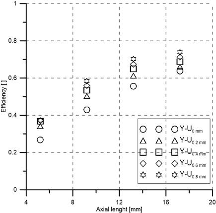
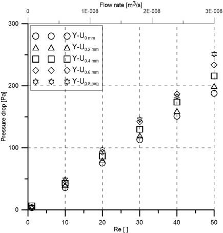
Figure 10 expresses the relationship between pressure drops with respect to Reynolds numbers and flow rate. Pressure drop increases with the increase of Reynolds number (and flow rate) for all mixers. The Y-U0.8 mm (H = 0.8 mm) has the highest pressure drop due to its longest channel length.
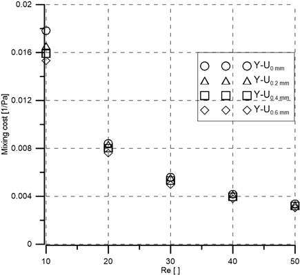
To have a better comparison between the five proposed mixers, the mixing cost (ratio of efficiency to pressure drop) with Reynolds numbers are also computed and described in Figure 11. It is clear that all mixers show almost the same mixing cost irrespective of Reynolds numbers. The reason behind this is that efficiency as well as pressure drop increase with the increase of vertical cylindrical height (H), so the ratio of efficiency to pressure drop remains almost constant.
5. Conclusions
This paper focuses on the design and analysis of the mixing performance of a new SAR-based ‘Y-U’ mixer. The mixer has four identical elements and each element consists of one ‘Y’ and one ‘U’ segment. Five mixers are proposed changing the vertical connecting cylindrical length (H) from 0 mm to 0.8 mm. Each time the vertical cylindrical length (H) is changed by 0.2 mm to see the effect on the mixing index. Mixing performance is computed numerically by FLUENT 15 varying Reynolds numbers (1≤Re≤50). A well-known SAR ‘H’ mixer is also studied and published experimental data was used to verify the numerical system. The proposed Y-U shows better performance compare to the H mixer at all examined Reynolds numbers. The efficiency of the Y-U mixer depends on the vertical connecting cylindrical length (H) and efficiency increases with the increase of the connecting cylindrical length; Y-U0.8 mm provides the highest mixing efficiency (75%) among all presented mixers. Efficiency also depends on the axial length as expected. There is no strong presence of secondary flow in the mixers, hence the mixing efficiency does not increase with the increase of Reynolds numbers. But at low Reynolds numbers (Re=1) mixing efficiency is high (90%) because the fluids have enough time to mix. The mixing cost is also calculated and all mixers show almost the same values. Hence all variations of Y-U mixers can be applicable in low Reynolds numbers.
References
[1] D. Wang, D. Ba, K. Liu, M. Hao, Y. Gao, Z. Wu, and Q. Mei, “A Numerical Research of Herringbone Passive Mixer at Low Reynold Number Regime”, micromachines, vol. 8, no. 325, doi: 10.3390/mi8110325. View Article
[2] V. Khaydarov, E. S. Borovinskaya, and W. Reschetilowski, “Numerical and experimental investigations of a micromixer with chicane mixing geometry,” Appl. Sci., vol. 8, no. 12, Dec. 2018, doi: 10.3390/app8122458. View Article
[3] C. Y. Lee, W. T. Wang, C. C. Liu, and L. M. Fu, “Passive mixers in microfluidic systems: A review,” Chemical Engineering Journal, vol. 288. Elsevier, pp. 146–160, Mar. 15, 2016, doi: 10.1016/j.cej.2015.10.122. View Article
[4] S. Rampalli, T. M. Dundi, S. Chandrasekhar, V. R. K. Raju, and V. P. Chandramohan, “Numerical Evaluation of Liquid Mixing in a Serpentine Square Convergent-divergent Passive Micromixer,” Chem. Prod. Process Model., vol. 15, no. 2, pp. 1–11, 2020, doi: 10.1515/cppm-2019-0071. View Article
[5] A. Enders, I. G. Siller, K. Urmann, M. R. Hoffmann, and J. Bahnemann, “3D Printed Microfluidic Mixers—A Comparative Study on Mixing Unit Performances,” Small, vol. 15, no. 2, Jan. 2019, doi: 10.1002/smll.201804326. View Article
[6] M. Guo, X. Hu, F. Yang, S. Jiao, Y. Wang, H. Zhao, G. Luo, and H. Yu, “Mixing Performance and Application of a Three-Dimensional Serpentine Microchannel Reactor with a Periodic Vortex-Inducing Structure,” Ind. Eng. Chem. Res., vol. 58, no. 29, pp. 13357–13365, Jul. 2019, doi: 10.1021/acs.iecr.9b01573 View Article
[7] V. Khaydarov, E. S. Borovinskaya, and W. Reschetilowski, “Numerical and experimental investigations of a micromixer with chicane mixing geometry,” Appl. Sci., vol. 8, no. 12, pp. 3–6, 2018, doi: 10.3390/app8122458. View Article
[8] A. Usefian and M. Bayareh, “Numerical and experimental investigation of an efficient convergent–divergent micromixer,” Meccanica, vol. 55, no. 5, pp. 1025–1035, 2020, doi: 10.1007/s11012-020-01142-0. View Article
[9] M. Juraeva and D. J. Kang, “Mixing performance of a cross-channel split-and-recombine micro-mixer combined with mixing cell,” Micromachines, vol. 11, no. 7, Jul. 2020, doi: 10.3390/mi11070685. View Article
[10] M. Bayareh, M. N. Ashani, and A. Usefian, “Active and passive micromixers: A comprehensive review,” Chemical Engineering and Processing - Process Intensification, vol. 147. Elsevier B.V., Jan. 01, 2020, doi: 10.1016/j.cep.2019.107771. View Article
[11] V. Viktorov and M. Nimafar, “A novel generation of 3D SAR-based passive micromixer: Efficient mixing and low pressure drop at a low Reynolds number,” J. Micromechanics Microengineering, vol. 23, no. 5, 2013, doi: 10.1088/0960-1317/23/5/055023. View Article
[12] M. A. Ansari, K. Y. Kim, K. Anwar, and S. M. Kim, “A novel passive micromixer based on unbalanced splits and collisions of fluid streams,” J. Micromechanics Microengineering, vol. 20, no. 5, 2010, doi: 10.1088/0960-1317/20/5/055007. View Article
[13] S. Hossain and K. Y. Kim, “Mixing analysis of passive micromixer with unbalanced three-split rhombic sub-channels,” Micromachines, vol. 5, no. 4, pp. 913–928, 2014, doi: 10.3390/mi5040913. View Article
[14] W. Raza and K. Y. Kim, “Asymmetrical split-and-recombine micromixer with baffles,” Micromachines, vol. 10, no. 12, Dec. 2019, doi: 10.3390/mi10120844. View Article
[15] S. W. Lee and S. S. Lee, “Rotation effect in split and recombination micromixing,” Sensors Actuators, B Chem., vol. 129, no. 1, pp. 364–371, 2008, doi: 10.1016/j.snb.2007.08.038. View Article
[16] T. S. Sheu, S. J. Chen, and J. J. Chen, “Mixing of a split and recombine micromixer with tapered curved microchannels,” Chem. Eng. Sci., vol. 71, pp. 321–332, Mar. 2012, doi: 10.1016/j.ces.2011.12.042. View Article
[17] K. Ohkawa, T. Nakamoto, Y. Izuka, Y. Hirata, and Y. Inoue, “Flow and mixing characteristics of σ-type plate static mixer with splitting and inverse recombination,” Chem. Eng. Res. Des., vol. 86, no. 12, pp. 1447–1453, Dec. 2008, doi: 10.1016/j.cherd.2008.09.004. View Article
[18] J. Li, G. Xia, and Y. Li, “Numerical and experimental analyses of planar asymmetric split-and-recombine micromixer with dislocation sub-channels,” J. Chem. Technol. Biotechnol., vol. 88, no. 9, pp. 1757–1765, 2013, doi: 10.1002/jctb.4044. View Article
[19] G. Xia, J. Li, X. Tian, and M. Zhou, “Analysis of flow and mixing characteristics of planar asymmetric split-and-recombine (P-SAR) micromixers with fan-shaped cavities,” Ind. Eng. Chem. Res., vol. 51, no. 22, pp. 7816–7827, 2012, doi: 10.1021/ie2026234. View Article
[20] S. Hardt, H. Pennemann, and F. Schönfeld, “Theoretical and experimental characterization of a low-Reynolds number split-and-recombine mixer,” Microfluid. Nanofluidics, vol. 2, no. 3, pp. 237–248, May 2006, doi: 10.1007/s10404-005-0071-6. View Article
[21] D. S. Kim, S. H. Lee, T. H. Kwon, and C. H. Ahn, “A serpentine laminating micromixer combining splitting/recombination and advection,” Lab Chip, vol. 5, no. 7, pp. 739–747, 2005, doi: 10.1039/b418314b. View Article
[22] G. Orsi, M. Roudgar, E. Brunazzi, C. Galletti, and R. Mauri, “Water-ethanol mixing in T-shaped microdevices,” Chem. Eng. Sci., vol. 95, pp. 174–183, May 2013, doi: 10.1016/j.ces.2013.03.015. View Article
[23] A. Usefian and M. Bayareh, “Numerical and experimental investigation of an efficient convergent–divergent micromixer,” Meccanica, vol. 55, no. 5, pp. 1025–1035, May 2020, doi: 10.1007/s11012-020-01142-0. View Article
[24] M. Nimafar, V. Viktorov, and M. Martinelli, “Experimental comparative mixing performance of passive micromixers with H-shaped sub-channels,” Chem. Eng. Sci., vol. 76, pp. 37–44, Jul. 2012, doi: 10.1016/j.ces.2012.03.036. View Article
[25] M. Nimafar, V. Viktorov, and M. Martinelli, “Experimental Investigation of Split and Recombination Micromixer in Confront with Basic T- and O- type Micromixers,” vol. 2, no. 5, pp. 61–69, 2012, doi: 10.5923/j.mechanics.20120205.02. View Article
[26] V. Viktorov, M. R. Mahmud, and C. Visconte, “Design and characterization of a new H-C passive micromixer up to Reynolds number 100,” Chem. Eng. Res. Des., vol. 108, 2016, doi: 10.1016/j.cherd.2015.12.005. View Article
[27] J. M. Park, D. S. Kim, T. G. Kang, and T. H. Kwon, “Improved serpentine laminating micromixer with enhanced local advection,” Microfluid. Nanofluidics, vol. 4, no. 6, pp. 513–523, Jun. 2008, doi: 10.1007/s10404-007-0208-x. View Article
[28] W. Raza, S. Hossain, and K. Y. Kim, “A review of passive micromixers with a comparative analysis,” Micromachines, vol. 11, no. 5. MDPI AG, May 01, 2020, doi: 10.3390/MI11050455. View Article
[29] N. Nguyen, Micromixers: Fundamentals, Design and Fabrication. 2011.
[30] C. K. Chung and T. R. Shih, “A rhombic micromixer with asymmetrical flow for enhancing mixing,” J. Micromechanics Microengineering, vol. 17, no. 12, pp. 2495–2504, Dec. 2007, doi: 10.1088/0960-1317/17/12/016. View Article
[31] X. Shi, L. Wang, S. Huang, and F. Li, “A novel passive micromixer with array of Koch fractal obstacles in microchannel,” J. Dispers. Sci. Technol., vol. 42, no. 2, pp. 236–247, 2021, doi: 10.1080/01932691.2019.1674156. View Article
[32] T. Dehghani, F. Sadegh Moghanlou, M. Vajdi, M. Shahedi Asl, M. Shokouhimehr, and M. Mohammadi, “Mixing enhancement through a micromixer using topology optimization,” Chem. Eng. Res. Des., vol. 161, pp. 187–196, Sep.2020. View Article