Journal of Fluid Flow, Heat and Mass Transfer (JFFHMT)
ISSN: 2368-6111

Volume 8 - Year 2021 - Pages 199-216
DOI: 10.11159/jffhmt.2021.022
A Transient Response Comparison of a Conventional and a Meso Heat Exchanger under Mass Flow and Temperature Step Changes
Shahram Fotowat1*, Serena Askar1, Amir Fartaj1
1University of Windsor, Department of mechanical,
automotive, and materials engineering,
401 sunset avenue, Windsor, Ontario, Canada, N9B3P4
fotowat@uwindsor.ca*, askars@uwindsor.ca , fartaj@uwindsor.ca
*corresponding author
Abstract - The increasing worldwide energy consumption problem motivates the effective management of thermal systems. A heat exchanger is an important component in many thermal systems, such as a radiator of an engine cooling system in vehicles. Heat exchangers are generally designed and characterized to work under steady-state conditions. However, a change in operating conditions exposes heat exchangers to a transient state, therefore, it is important to study their transient responses for better control of the system and efficiency improvement. In this study, the experimental responses of two types of heat exchangers: conventional, and meso heat exchangers subjected to a sudden change in inlet temperature and mass flow rate of the hot fluid are compared and presented. The transient outlet temperature responses of both hot and cold fluids as well as the transient heat exchanger effectiveness and heat transfer rate variations are found in this work. A general empirical correlation is obtained for the hot fluid transient dimensionless outlet temperature subjected to mass flow rate step change. Furthermore, results show that the meso heat exchanger exhibited higher heat transfer rate and effectiveness as well as reached steady state faster than the conventional heat exchanger. Even though the meso heat exchanger has a longer initial delay time, it possesses a higher response time than a conventional heat exchanger, regardless of the step change.
Keywords: Step change; Response time; Dynamic performance; Transient Response; Heat exchanger
© Copyright 2021 Authors - This is an Open Access article published under the Creative Commons Attribution License terms Creative Commons Attribution License terms. Unrestricted use, distribution, and reproduction in any medium are permitted, provided the original work is properly cited.
Date Received: 2020-07-12
Date Accepted: 2021-04-16
Date Published: 2021-07-12
Nomenclature
1. Introduction
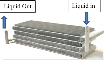
Heat exchangers are frequently comprised in the industrial and HVAC systems and have an imperative role to play. Many researchers devoted themselves implementing innovative ideas to improve and efficiently utilize heat exchangers. One of the major considerations of improvement is space limitation which is becoming progressively important in designing many systems. For this reason, different size heat exchangers are introduced. The classification based on the ratio of area to volume can be found in Shah and Seculik [1]. One of their classification is the meso heat exchanger in which the surface area to volume ratio must be equal or greater than 3000 m2/m3 and a hydraulic diameter between 1µm ≤ Dh ≤ 1mm. The heat exchanger of the current investigation has a surface area density of 4000 m2/m3 with a channel diameter of 1 mm which can be considered a meso heat exchanger.
In addition to size enhancement, the improvement of gaining more internal heat transfer by means of using a serpentine bend is investigated by Dehghandokht et al. [2]. Aiming to examine the influence of serpentine in heat exchangers, the thermo-hydraulic characteristics of a serpentine meso heat exchanger with parallel channels were numerically studied. They modelled the effect of serpentine on heat transfer and compared the results with the experimental data using the same geometry and operating conditions. It was found that the adiabatic serpentine in a meso heat exchanger slab resulted in increasing the heat transfer. Sousa et al. [3] analysed a micro heat exchanger designed for the waste heat recovery from a high concentration photovoltaic system. Test runs were performed to analyse the effect of different mass flow rates on the temperature difference between the inlet and outlet fluid ports.
Siddiqui et al. [4] used a meso heat exchanger to study its convective heat transfer characteristics. A uniform slab surface temperature distribution was found on the meso heat exchanger compared to non-uniform temperature distribution around the tubes of a conventional heat exchanger. Numerical simulation of fluid flow and heat transfer in channels of plate heat exchangers for heating domestic hot water was studied by Mandic [5]. The simulation model predicted the time of flow and temperature degradation within the channel which allowed a preventative maintenance on the heat exchanger plates to be performed in a timely manner.
The previous listed works were performed using steady state analysis; however, heat exchangers can be subjected to a change in their inlet conditions. In a system, when a change occurs to any of the input parameters, it takes time to reach the final state and get the system to stabilize. The focus on the transient behaviour of heat exchangers is increasing owing to the advances in the process control. The dynamic responses of each component need to be known to allow the full automation in a process plant.
Guha et al. [6] numerically investigated the dynamic behaviour of a heat exchanger network. A relative interaction between fluid streams and the identification of the process streams to inlet temperature change was demonstrated. They suggested possible points for temperature control in heat exchanger network. With the aim of improving the design of control strategies and energy efficiency, heat exchangers characteristics of data centres were numerically investigated by Gao et al. [7]. They also examined the transient performance of the heat exchanger under different change functions such as step, ramp and exponential variation to the hot fluid inlet temperature. They showed that transient nonuniform inlet temperatures affected both the steady state and transient performance of a cross flow heat exchanger.
The dynamic temperature response of unmixed fluids in crossflow heat exchangers with finite wall capacitance for variations in both temperature and mass flow rate was numerically studied by Mishra et al. [8]. Step and ramp changes in the mass flow of both hot and cold fluids, and step, ramp, exponential and sinusoidal changes in hot fluid inlet temperature were applied. Their results showed a rise in the exit temperatures once the larger disturbance is in the hot fluid, and a drop once the larger disturbance is in the cold fluid. Dynamic behaviour of a multi-pass cross flow heat exchanger under temperature and mass flow rate changes was numerically studied by Silaipillayarputhur et al [9]. Their analysis showed that for the case of step change in inlet temperature or mass flow rate of the minimum heat capacity fluid, pure cross flow circulating degrades the instant thermal performance of the heat exchanger relative to either parallel or counter flow circulating.
Mathematical model of the effect of fluid maldistribution in channels in a plate heat exchanger was presented by Prabhakara Rao and Das [10]. Their results indicated that the flow maldistribution severely affects the performance of plate heat exchangers and multipass can act as an important tool to reduce the deterioration in performance due to maldistribution. Silaipillayarputhur and Idem [11] presented finite difference equations for a transient finite difference model for the step responses of a single pass crossflow heat exchanger with variable inlet temperatures and mass flow rates. The steady state results from their transient model were found to be in a good agreement with the results obtained from steady state model in the literature. Syed et al. [12] examined the dynamic response of an unmixed, single pass, cross flow heat exchanger subjected to a step up in temperature of the minimum capacity rate fluid using an implicit central finite difference method. A delay in the transient response of the minimum capacity rate fluid was found compared to an immediate temperature response for the maximum capacity rate fluid. Roetzel et al. [13] introduced a general mathematical model for anticipating temperature responses of one-dimensional flow heat exchangers. They assessed the transient parameters of heat exchangers used for the automatic control systems depending on analytical and numerical methods.
Yao et al. [14] studied the transient responses of a water-to-air heat exchanger for optimizing the control of an enhanced energy efficiency of an HVAC system. They developed a dynamic model for humidity, air and water exit temperatures in the cases of start up the chiller, shut down the chiller and a rise in the water flow rate. The results displayed that the input changes and the initial conditions yielded noteworthy effect on the proportionality coefficient of the response variables, but slight effect on the time constant of the response variables. Abdelghani-Idrissi et al. [15] investigated the transient response of a counterflow double pipe heat exchanger. They predicted the response time of the hot fluid subjected to a flow rate step change. A comparison of the time constant for positive and negative flow rate step changes showed asymmetric behaviour of the heat exchanger.
Del Valle et al [16] experimentally measured the dynamic response of a 12”X12” single pass cross flow heat changer in a hybrid air–liquid cooling system of a data center. The test rig was able to produce step, ramp and frequency changes of water temperature and flow rate. They found that the sinusoidal variation on the water flow rate was responsible for the delay between the inlet temperature variation and both outlet temperatures. Shorter to no reaction was also found between the inlet flow perturbation and the outlet temperature responses.
The listed previous work showed the lack in the transient experimental work and the need to analyse the behaviour of different heat exchangers such as compact ones (due to the increasing demand of the industry). For this purpose, Fotowat et al [17] investigated the transient behaviour of a crossflow meso heat exchanger under different temperature step changes. The effect of the change in the inlet liquid water temperature on different parameters such as the outlet temperature and initial delay time of both air and water sides was studied.
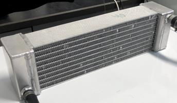
The current study aims to examine the dynamic response of a conventional heat exchanger (prototype car radiator, Figures 3b, 4b) and compare it with a meso heat exchanger with both being subjected to variations in inlet liquid temperatures as well as flow rates while the air flow rate and temperature are held constant. Both heat exchangers under investigation are designed locally with the same length of 12”, depth of 2” and height of 2”, which occupy the same volume. Note that the depth of the meso heat exchanger examined in this work is half the depth of the meso heat exchanger employed in [17]. The focus of this work is relevant to the industry as well as the academic research community. Several processes undergo transient operation, which if not well-understood, could lead to unexpected performances of heat exchangers. By focusing on heat exchangers with the same overall dimensions but different type of geometries, investigation not only provides insights into the transient behaviour, but also the effect of geometry, such as the multi-channel vs single channel flow. In addition, the lack of availability of adequate and well-stablished experimental transient data for conventional and meso heat exchangers, signifies the importance of current work as a source for future scientists in heat exchanger design.
2. Transient Experimental Setup
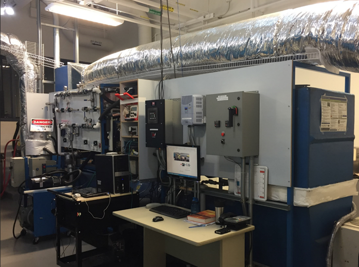
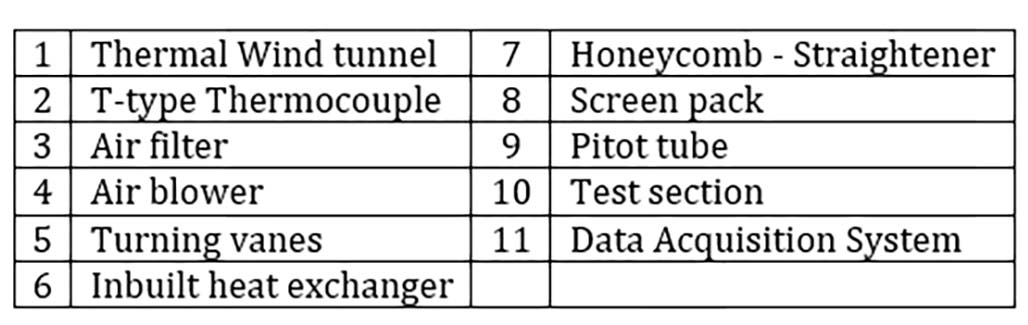
The fully instrumented experimental set up that is used in this study is shown in Figures 1 and 2. It is designed to investigate the steady state as well as the transient response of different types of heat exchangers. The test section is capable to encompass different types of heat exchangers for performance comparison. The main working fluids used in these heat exchangers are DI-water and air. The experimental data are monitored and recorded using a data acquisition system (DAQ). The full instrumentation of the system includes having differential pressure transducers and thermocouples on the airside, while, an inline Coriolis mass flow meter, resistance temperature detectors (RTDs), pressure transducers (PTDs), 10-ton chiller and 20kw inline heater on the liquid side.
The test chamber that is placed in the center of the wind tunnel is made-up from transparent polycarbonate sheets with high thermal resistance. It has a rectangular shape with a cross section of 4”x 12” [0.1016 m x 0.3048 m] and a depth of 24” [0.6096 m]. For this study the two heat exchangers are situated inside the test chamber alternatively to study and compare their transient thermal behavior; a meso heat exchanger and a conventional heat exchanger. For all the experimental runs, the inlet conditions of the airside are kept constant at 13°C and 222g/s or 6m/s for both heat exchangers. These fixed conditions are achieved using a thermal wind tunnel equipped with an inbuilt heat exchanger that provides a full control on the air inlet temperature. Step changes in the hot liquid inlet temperature and flow rate are applied. The mass flow step changes varied from an initial value of 20 g/s to (10, 16, 30, 40, 50) g/s at a constant hot liquid temperature of 70°C. This constant hot liquid temperature is obtained through an inline heater and additional brazed and plate heat exchangers to supply the desired hot liquid temperature to flow inside the meso heat exchanger. On the other hand, the liquid step variation in temperature started from an initial value of 22°C to (33, 44, 55, 66, 77) °C at a constant hot liquid mass flow rate of 60g/s.
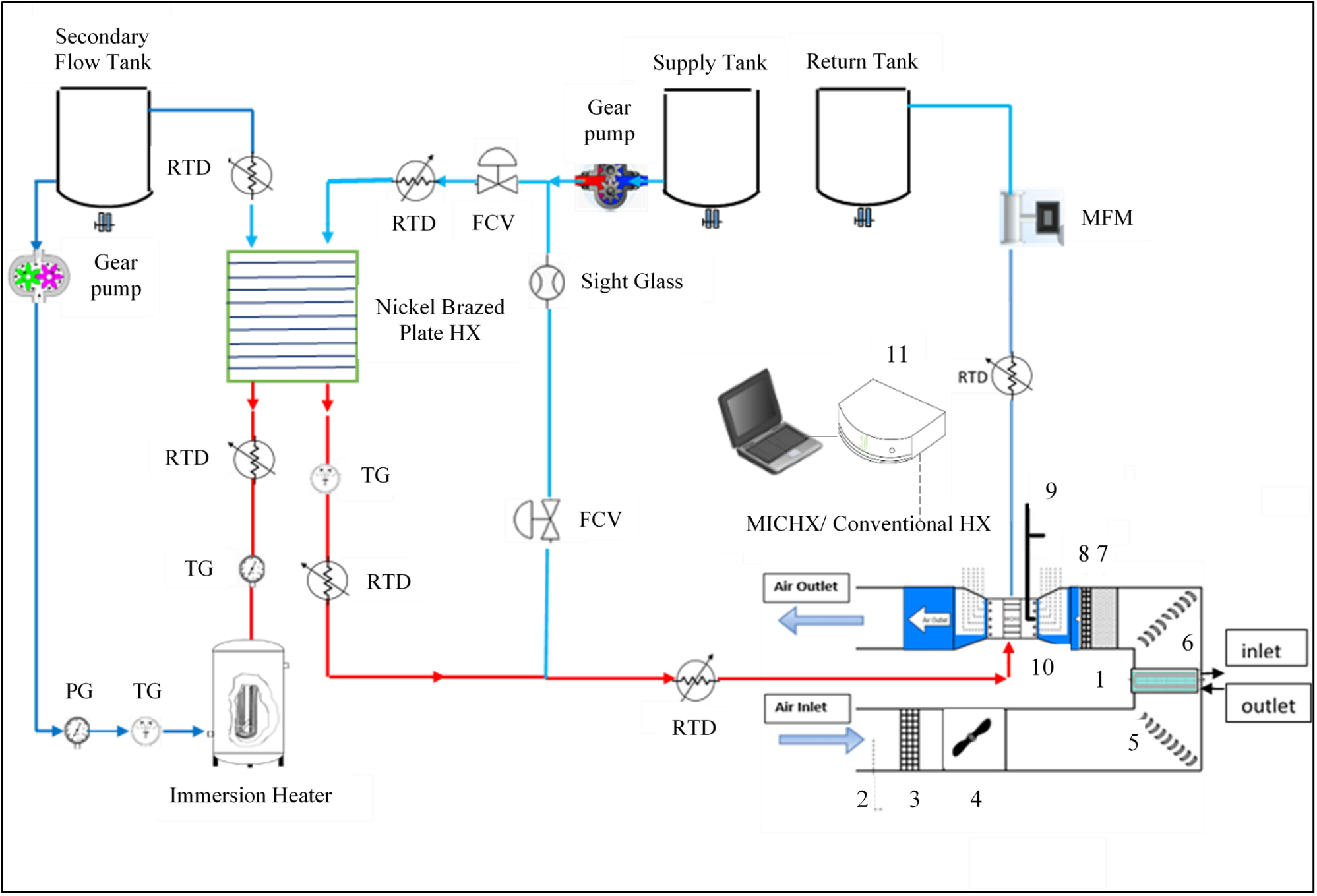
2.1. Liquid Side Circuit
The liquid side consists of two circuits, primary and secondary circuits. The secondary circuit produces a desired flow and temperature using secondary flow pump and heater equipped with a microprocessor. This flow provides heat to the primary fluid using a brazed plate heat exchanger (BPHX). The flow of the primary fluid divides into two adjustable portions. One portion goes through a needle control valve (direct fluid line) without heating and the other portion goes through another needle control valve (bypass fluid line). Then the bypass flow goes through the BPHX to get heat from the secondary flow before mixing with the cold fluid to produce a desired inlet fluid temperature of the main heat exchanger. The predetermined conditions of the control flow valves are recorded before running the transient test. The directional control flow valve provides precision flow control using different colors for every turn of the adjusting knob and each turn has a gradient of 10 equal degrees. A flow control valve conveys a constant flow regardless of the pressure drop through the valve.
2.2. Mass Flow Rate Step Change Procedure
To create any mass flow rate step variation from its initial condition, the step-by-step procedure is appended below:
The secondary circuit of plate heat exchangers is initialized by
- Starting the secondary circuit gear pump
- Starting the inline 20kw immersion heater
The intention is to heat up the water of secondary circuit until its temperature reaches to pre-set value with an offset of 0.1°C.
Then, the main circuit gear pump is turned on letting primary fluid, water, passes through the system.
Initially, the primary fluid mass flow rate of 20g/s is maintained by controlling the pump frequency. Then, adjusting the inlet fluid temperature at 70°C.
When the outlet temperature of the primary fluid reaches steady state, a step change is applied as in the following,
- Promptly change the frequency of the pump to get to the next primary fluid mass flow rate.
- Simultaneously adjusting both direct and bypass fluid valves at predetermined positions to keep the inlet fluid temperature at 70°C.
2.3. Tested Heat Exchangers
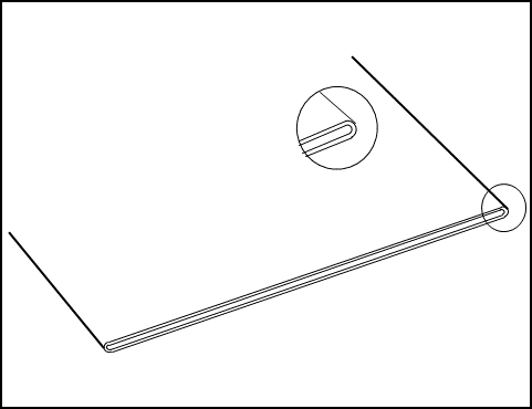
The heat exchangers used in this study are cross flow air to liquid heat exchangers with the same dimensions, fin density and thickness, and both are made of aluminium. The thickness of the slab in the meso heat exchanger is identical to the depth of the conventional heat exchanger. Figures 3 and 4 show the specifications and pictures of the heat exchangers, while Table 1 and Table 2 list the specification for each exchanger.
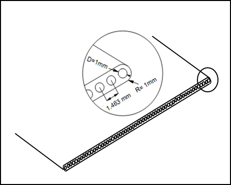
(a) Multi channel
(b) Single channel
(a)
(b)
Table 1. Meso heat exchanger specifications
|
Heat exchanger specifications |
Dimensions |
|
Channel diameter (m) |
0.001 |
|
No. of channels in a slab |
34 |
|
No. of slabs |
5 |
|
Slab thickness (m) |
0.002 |
|
Heat exchanger (slab) length (mm) |
0.305 |
|
Heat exchanger (slab) width (mm) |
0.102 |
|
Heat exchanger height (mm) |
0.102 |
|
Fin height (m) |
0.0158 |
|
Fin depth (m) |
0.102 |
|
Liquid-side heat transfer surface areas (m2) |
0.156 |
|
Air-side heat transfer slab areas (m2) |
0.139 |
|
Fin density (fins per cm length of slab) |
5 |
|
Fin heat transfer surface areas (m2) |
1.154 |
Table 2. Conventional heat exchanger specifications
|
Heat exchanger specifications |
Dimensions |
|
Channel size, H x W (m x m) |
0.001 x 0.051 |
|
No. of channels in a slab |
1 |
|
No. of slabs |
8 |
|
Slab thickness (m) |
0.002 |
|
Heat exchanger (slab) length (m) |
0.305 |
|
Heat exchanger (slab) width (m) |
0.102 |
|
Heat exchanger height (m) |
0.102 |
|
Fin height (m) |
0.0076 |
|
Fin depth (m) |
0.102 |
|
Fin density (fins / cm length of slab) |
5 |
|
Liquid-side heat transfer surface areas (m2) |
0.235 |
|
Air-side heat transfer slab areas (m2) |
0.230 |
|
Fin heat transfer surface areas (m2) |
1.008 |
3. Data reduction for the experiments
The outlet temperatures of both fluids and the thermal characteristics of the heat exchangers are evaluated by dimensional and non-dimensional parameters such as dimensionless temperature, heat transfer rate, and effectiveness.
The residence time (tres) defines the time it takes the hot liquid to pass through the heat exchanger and is presented as follows,

dividing time over the residence time, a dimensionless form of time (t*) is used for generalization purpose as,
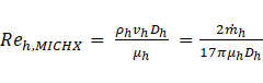
Reynolds number is found for the hot fluid based on the diameter of the channel and the amount of mass flow rate as follows,

Considering the geometry of the tested heat exchanger, meso, Reynolds number can be shown as,
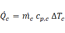
The heat transfer rates of both fluids are shown in the following,

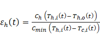
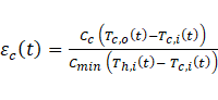
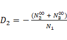
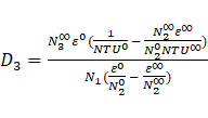
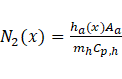
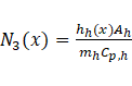
Heat exchangers are characterized by the heat transfer effectiveness ε representing the heat transfer rate over the maximum possible heat transfer rate and is found using the energy balance of the hot and cold fluids Cengel [18]. Cima and London [19] extended the idea of the heat transfer effectiveness to time dependency. This expression was also used by Gao et al. [20], Srihari and Das [21]. Starting with the general effectiveness definition,

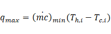
The maximum possible heat transfer rate is defined as,
Where, c=cv=cp refer to the fluid specific heat, the transient effectiveness is found as,
A measure of the accuracy of an experiment is given by its uncertainty. The uncertainty of some of the parameters that are used in this study is listed in table 3.
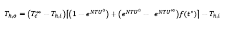
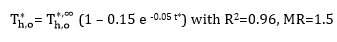
Using Yin and Jensen analytical model [22], the hot liquid outlet temperature ( ) is obtained as follows:
Then the f(t*) was found,
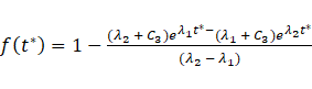
where,
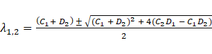
where,


The analytical approach is simplified for the outlet temperature of the hot fluid and is independent of position along the heat exchanger.
Table 3. Overall experimental uncertainty
|
Key parameters |
Relative uncertainties of mean value |
|
Rea |
±3.03% |
|
±7.82% |
|
|
|
±2.41 % |
|
Rew |
±4.57% |
|
±8.5% |
|
|
±5.79% |
4. Results and discussion
This section discusses the findings of the transient behaviour for the two heat exchangers as a result of step changes in the hot fluid inlet temperature and mass flow rate. The case of temperature change was performed under constant mass flow of both fluids and air inlet temperature. For this case, only the hot fluid inlet temperature was varied to steps of 1.5 to 3.5. The second case of varying the mass flow rate into steps of 0.5 to 2.5 was applied to the hot fluid inlet mass flow while keeping the fluids inlet temperatures and air mass flow rate constant. The comparison of the two heat exchangers is made for the two cases and the experimental results are used to compare and validate an analytical model in order to check its predictability of the experimental data.
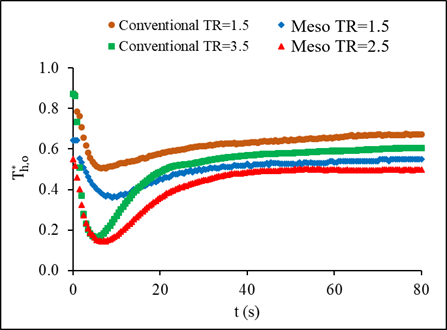
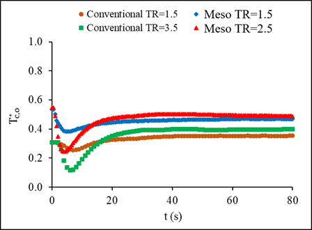
4.1. Meso and Conventional Heat Exchanger Comparison for Temperature Steps
Ratios of the new liquid inlet mass flow rate and flow temperature after step change over the initial liquid inlet mass flow rate and flow temperature are defined as mass flow rate ratio, MR and temperature ratio, TR respectively. Figure 5 illustrates the repeatability of the system for the range of MR and TR values. The experiments were repeated 3 times to check the precision of the data and the repeatability was found lower than 3%. The effect of the inlet temperature step change on the outlet temperature of both fluids for the meso and the conventional heat exchangers are presented in Figure 6. The airside inlet conditions were kept constant for both heat exchangers at 13°C inlet temperature and mass flow rate of 0.22 kg/s with constant hot liquid mass flow rate of 60 g/s. The comparison between the exchangers considered only the lowest and highest temperature steps of 1.5 and 3.5. The hot liquid outlet temperature of the conventional exchanger is found 9% and 15% for steps of 1.5 and 3.5, respectively, higher than the temperature of the meso heat exchanger. Considering the response time of each heat exchanger for the two steps, at 1.5, the meso heat exchanger showed a 78s response time compared to the 138s for the conventional heat exchanger. As the step gets higher to 3.5, the meso responded even faster within 38s compared to the conventional heat exchanger, which response time was 76s. This concludes a shorter response time for the meso leading to reaching steady state faster compared to the conventional heat exchanger.
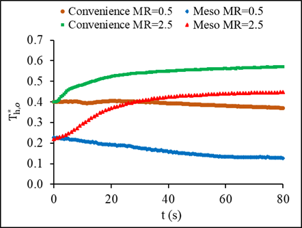
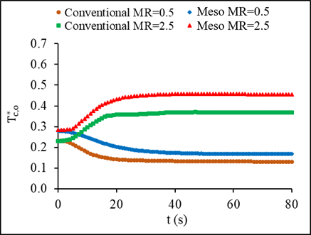
The effect of mass flow step changes on the outlet temperatures of the meso and conventional heat exchanger is illustrated in Figure 7. The hot liquid outlet temperature for two different mass flow steps was compared for the two heat exchangers. Considering a mass flow step of 0.5, the meso exhibited faster response time at 83s compared to the 178s in the conventional heat exchanger. In the case of higher mass flow step change of 2.5, the response time was still better for the meso at 50s compared to 143s for the conventional. While the meso recorded faster response time, its initial delay time was higher at 4.5s compared to the 0.7s of the conventional heat exchanger considering the case of a step change of 0.5. Therefore, regardless of the value of the step change applied to the hot liquid inlet mass flow rate, the Meso recorded better response time to reach the steady state than a conventional heat exchanger.
The reason for faster response time of the meso could be explained by the fact that the existence of the serpentine breaks the boundary layer. Then, a new boundary layer starts developing after each serpentine, which elevates the heat transfer rate. Moreover, the meso has higher heat transfer surface area compared to the conventional heat exchanger.
 (a) Mass flow step change
 (b) Temperature step change
 (a) Hot liquid outlet temperature
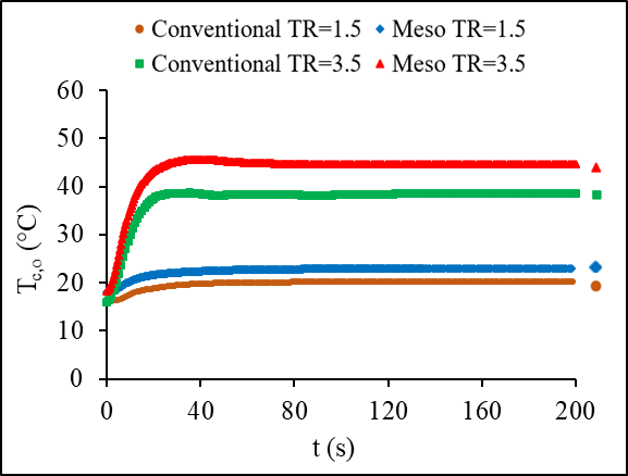 (b) Cold air outlet temperature
 (a)
(a) 
 (b)
(b) 
4.2. Analytical and experimental comparison for a conventional heat exchanger
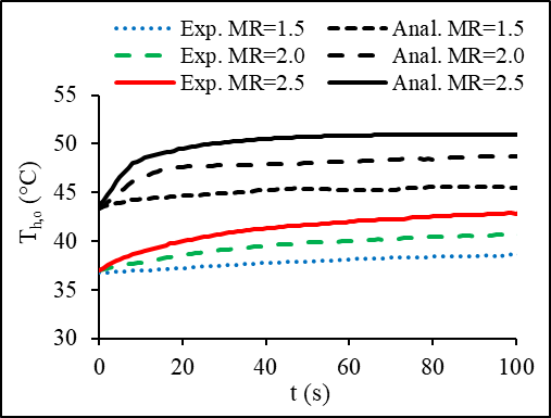
Figures 8 and 9 represent the current experimental and the analytical [22] results of the outlet temperatures of a traditional tube and fin heat exchanger. The experiments were performed by stepping up and down the mass flow rate while holding the cold airside inlet conditions constant at inlet temperature of 13°C and mass flow rate of 0.22 kg/s while the liquid side inlet temperature was held at 70°C. For a better comparison between the model and the experimental data, the initial delay and step time are removed from these figures. The analytical model predicted a 20% higher hot fluid outlet temperature than the experimental results. A possible explanation for this difference is the assumption made for the heat transfer coefficient to be constant along the heat exchanger to simplify and solve the governing equations.
 (a) Th,o at the steps ups
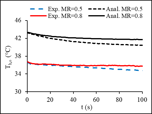 (b) Th,o at the steps downs
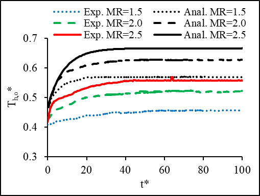 (a)
(a)  at the steps ups
 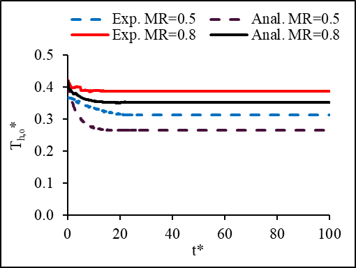 (b) at the steps downs
4.3 Comparison of results with literature (previous work)
Current experimental transient results in term of dimensionless temperature and time under MR=1.5 are compared with the numerical study for MR=1.25 of Mishra et al [8], as shown in Figure 10. The heat exchanger used for comparison is a single pass plate-fin crossflow heat exchanger while the current study uses a liquid to air cross flow meso heat exchanger. Longer dimensionless response time of 20 is required for the current study to reach steady state compared to 10 for Mishra et al. [8]. A sharp increase of the dimensionless temperature is found in their results when mass flow rate step is applied, while a gradual change is found for this study. The difference that is observed in the figure is due to the following factors: type of heat exchangers (plate-fin heat exchanger versus meso heat exchanger), flow-pass diameter, mass flow rate step variations. These parameters can influence both the outlet dimensionless temperature and the dimensionless time.
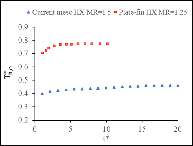 comparison of Current meso HX with a Plate-fin HX [8]
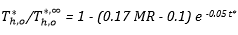
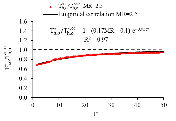
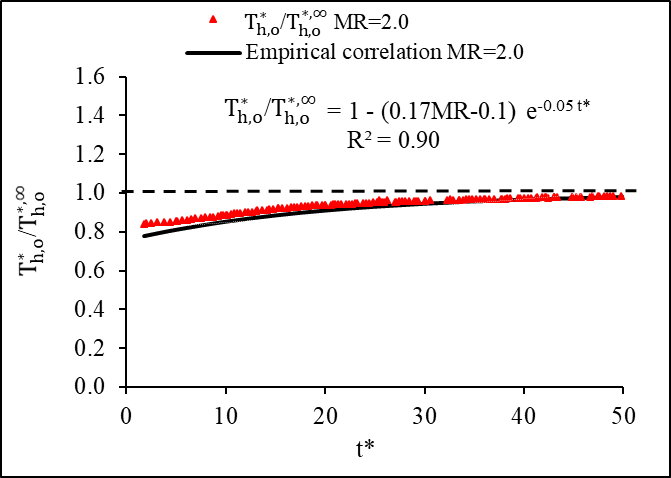
4.4. An Empirical Correlation of Hot Fluid Transient Dimensionless Outlet Temperature for Mass Flow Step Change
The ratio of the transient dimensionless hot fluid outlet temperature to its steady-state temperature with respect to dimensionless time is presented in Figure 11. The transient outlet temperature approached quasi-steady state for the mass flow step variation at a dimensionless time around 50. An empirical correlation is obtained for the step-up variation using eq. 28. The experimental data agreed well with the obtained empirical correlation as shown in the figures. Detailed regression analysis for the empirical correlation is discussed and presented in Appendix A.
 (a)
(a)
 (b)
(b)
 (c)
in a conventional HX
(c)
in a conventional HX
4.5. Heat transfer rate comparison of the meso and the conventional heat exchanger
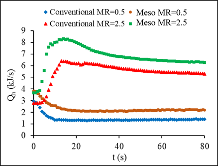
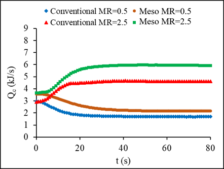
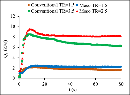
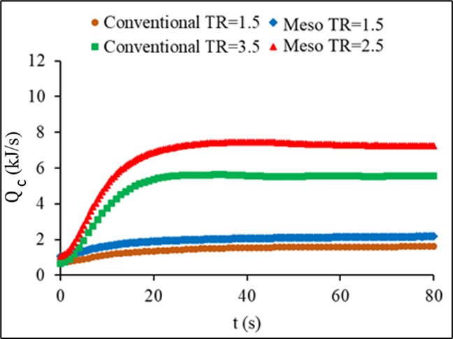
The effect of varying the inlet conditions on heat transfer rate of both heat exchangers is shown in Figures 12 and 13. To examine this effect, the variation was applied to hot liquid inlet temperature then its mass flow rate. Higher steps of temperature, 3.5, and mass flow rate, 2.5, resulted in a hot fluid reaching a peak before achieving steady state. The heat transfer of the two heat exchangers, meso and the conventional, based on the hot fluid side experienced higher increase to a maximum peak before reaching the steady state, and this can be clearly seen for higher step changes. The cold fluid heat transfer increase followed a different trend with no peak recorded for the transient period. The reason behind the increase in the hot fluid side heat transfer rate might be due to the sudden increase of the liquid inlet temperature or mass flow rate while the airside inlet conditions remained constant. In the case of temperature step change, the rate of heat transfer enhancement in the meso heat exchanger is found about 30% higher than the conventional heat exchanger whereas it is 21% higher for the case of mass flow steps. This is because of the higher heat transfer surface area, existence of serpentine, as well as the secondary flow in the serpentine that caused the boundary layer to break and to develop a new layer.
 (a) Qh
 (b) Qc
 (a) Qh
 (b) Qc
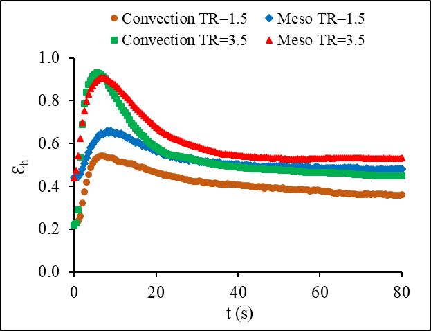
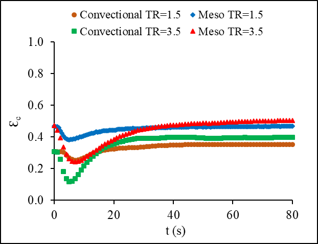
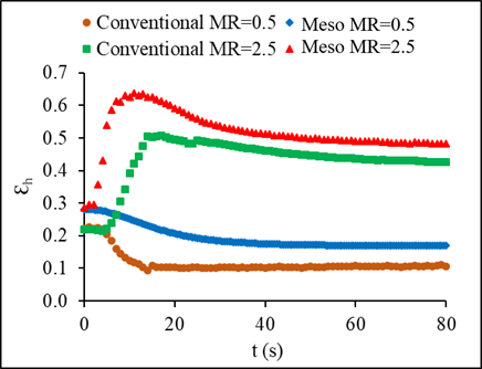
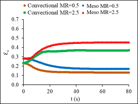
4.6. Comparison of the Transient Effectiveness in a Conventional and Meso Heat Exchanger
The transient effectiveness change with time for both fluids is shown in Figure 14 for the case of inlet temperature step change and in Figure 15 for the case of inlet mass flow step change. The results show an increase in the transient effectiveness based on the hot fluid of about 15-25% for temperature steps of 0.5 and 2.5, respectively, which was higher in the meso when compared to the conventional heat exchanger and about 11-35% for mass flow steps of 0.5 and 2.5, respectively. A reverse trend is noticed in the cold fluid transient effectiveness with a noticeable decrease of about 21-25% in the case of stepping up in temperature and 20-24% for the case of stepping up in mass flow rate.
 (a)
(a)
 (b)
(b)
 (a)
(a)
 (b)
(b)
4.7. Dimensionless Outlet Temperatures with Time for the Conventional and Meso Heat Exchanger
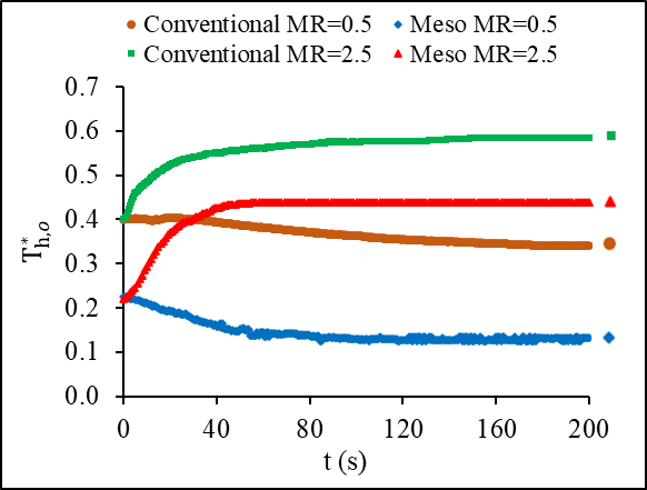
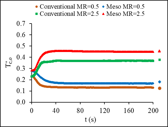
Figures 16a and 16b represent the behavior of the dimensionless outlet temperature of both fluids in each heat exchanger for the condition of inlet temperature variations. A similar trend between the hot and cold fluids displayed the same negative dent, which is the decrease in effectiveness during transient period before reaching steady state. The increase of the hot fluid dimensionless temperature in the steady state reached 18% whereas, the increase in the cold fluid was higher at 28%. Figures17a and b show how the dimensionless temperature changes with time for mass flow step changes. Stepping up in mass flow rate resulted in an increase in the dimensionless outlet temperature for both fluids, while it is not the case for stepping down. A step down in mass flow rate led to a decrease in the dimensionless outlet temperature of both fluids.
 (a)
(a)
 (b)
(b)
 (a)
(a)
 (b)
(b)
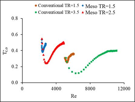
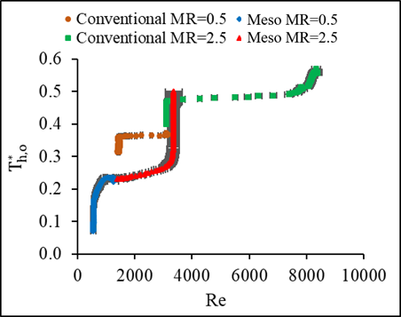
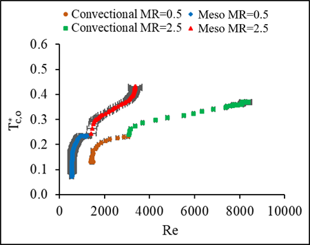
4.8. Dimensionless Outlet Temperatures With Re for the Conventional and Meso Heat Exchanger
The dimensionless outlet temperature of both fluids in the heat exchangers is presented with Reynolds number for the conditions of temperature and mass flow steps in Figures 18 and 19. The step variation in the liquid mass flow in this experiment ranged between Reynolds numbers of about 550 to 3356 for the meso and about 1462 to 8295 for the conventional cross flow heat exchanger. While in the case of temperature step changes, Reynolds number ranged between 5025 to 11057 for the meso and about 2294 to 4835 for the conventional heat exchanger. A negative peak was found in the dimensionless outlet temperature at different temperature step changes. Nonetheless, the dimensionless temperature for the mass flow variations showed different trend than that of the temperature step changes. The initial delay time increased as the step change increased, and it is found higher for the meso than the conventional heat exchanger.
 (a)
(a)
 (b)
(b)
 (a)
(a)
 (b)
(b)
5. Conclusions
In this work, the dynamic response of crossflow conventional and meso heat exchangers is investigated experimentally. Their transient performance under the inlet liquid mass flow step-change range of 0.5 to 2.5, and the temperature step-change range of 1.5 to 3.5 was evaluated. The following findings are obtained.
- Although the meso possessed longer initial delay time, its response time is higher than a conventional heat exchanger, regardless of the step variation.
- An analytical model from the literature is compared in this study with the experimental work presented and found a 20% overestimation; this can be a result of the assumptions used when creating the model.
- The dimensionless response time for the current meso heat exchanger is observed to be longer than the plate- fin heat exchanger while its rate of change for dimensionless outlet hot fluid is found to be lower.
- A general empirical correlation is developed for the hot fluid outlet temperature in a conventional heat exchanger under inlet mass flow step-changes and agrees well with the experimental results.
- The meso heat exchanger reached steady state condition faster with a higher heat transfer rate and effectiveness than the conventional heat exchanger.
Acknowledgement
This work is supported by the Natural Sciences and Engineering Research Council of Canada provided at the University of Windsor.
References
[1] R.K. Shah and D.P. Sekulic, “Fundamentals of heat exchanger design,” New Jersey: John Willey & sons Inc., 2003. ISBN: 0-471-32171-0. View Article
[2] M. Dehghandokht, M.G. Khan, A. Fartaj, and s. Sanaye, “Numerical study of fluid flow and heat transfer in a multi-port serpentine meso-channel heat exchanger,” Applied Thermal Engineering, 31, 1588-1599, 2011. doi.org /10.1016/j.applthermaleng. 2011. 01.035. View Article
[3] I. F. de Sousa, C. P. N. Cotta, D. C. Guerrieri, and M. K. Tiwari, “On the Thermal Performance of a Microparallel Channels Heat Exchanger,” Journal of thermal science and engineering applications, Vol.11, Issue 2, PP. 021006 1-11, April 2019. View Article
[4] F.A. Siddiqui, E.S. Dasgupta, and A. Fartaj, “Experimental investigation of air side heat transfer and fluid flow performances of multi-port serpentine cross-flow meso heat exchanger,” International Journal of Heat Fluid Flow, 33: 1, 207–219, 2012. doi: 10.1016/j.ijheatfluidflow. 2011.12. 001. View Article
[5] D. Mandic, “Numerical Simulation of Fluid Flow and Heat Transfer through Channels of Plate Heat Exchangers,” J. Fluid Flow, Heat and Mass Transfer, Vol.5, pp. 71-75, 2018. SSN: 2368-6103, DOI: 10.11159/jffhmt.2018.007. View Article
[6] C. Guha, and A. Chaudhuri, “Transient analysis of heat exchanger network,” Journal of the Institution of Engineers, Chemical Engineering Division, 87, 51-59, 2007. ISSN: 00203351.
[7] T. Gao, B. Sammakia, J. Geer, A. Ortega, and R. Schmidt, “Transient Effectiveness Characteristics of Cross Flow Heat Exchangers in Data Center Cooling Systems,” 14th IEEE ITHERM Conference, PP. 688-697, 2014. View Article
[8] M. Mishra, P.K. Das, and S. Sarangi, “Transient behaviour of crossflow heat exchangers due to perturbations in temperature and flow,” International Journal of Heat and Mass Transfer 49, 1083–1089, 2006. View Article
[9] K. Silaipillayarputhur, and S.A. Idem, “Transient response of a cross flow heat exchangers subjected to temperature and flow perturbations,” Proceedings of the ASME, international Mechanical Engineering Congress and Exposition, Houston, Texas, Nov. 2015.
[10] B. Prabhakara Rao, and Sarik K. Das, “Effect of flow distribution to the channels on the thermal performance of the multipass plate heat exchangers,” Heat Transfer Engineering, 25:8 48-59, 2004. View Article
[11] K. Silaipillayarputhur, and S. Idem, “Step response of a single-pass crossflow heat exchanger with variable inlet temperatures and mass flowrates,” Thermal Science and Engineering Applications, 4:4, 2012, 044501 1-6. View Article
[12] F.H. Syed, and S. Idem, “Transient performance of a cross flow heat exchanger using finite difference analysis,” ASME, Proceedings of International Mechanical Engineering Congress and Exposition, IMECE2008, Boston, Massachusetts, USA, Oct-Nov 2008. View Article
[13] W. Roetzel, M. Li, and X. Luo, “Dynamic behaviour of heat exchangers, Advanced Computational Methods in Heat Transfer,” 35, 451-460, 2002. ISBN 1-85312-906-2.
[14] Y. Yao, M. Huang, J. Mo, and S. Dai, “State-space model for transient behavior of water-to-air surface heat Exchanger,” International Journal of Heat and Mass Transfer,” 64, 173–192, 2013. View Article
[15] M.A. Abdhelghani-Idrissi, F. Bagui, and L. Estel, “Analytical and experimental response time to flow rate step change along a counterflow double pipe heat exchanger,” International Journal of Heat and Mass Transfer, 44 3721 – 3730, 2001. View Article
[16] M. Del Valle, and A. Ortega, “Experimental Characterization of the Transient Response of Air/Water Crossflow Heat Exchangers for Data Center Cooling Systems,” International Technical Conference and Exhibition on Packaging and Integration of Electronic and Photonic Microsystems, IPACK2015-48375, 1- 9, 2015. View Article
[17] S. Fotowat, S. Askar, and A. Fartaj “Transient response of a meso heat exchanger with temperature step variation,” International Journal of Heat and Mass Transfer, 122, 1172–1181, 2018. View Article
[18] Y. A. Cengel, “Heat Transfer: A Practical Approach,” New York: McGraw-Hill Higher Education, 2006. ISBN-13: 978-0070634534.
[19] R.M. Cima, and A.L. London, “Transient Response of a Two-Fluid Counter-Flow Heat Exchanger-The Gas-Turbine Regenerator,” Transactions of ASME, 80, 1169–1179, 1958. View Article
[20] T. Gao, B. Sammakia, J. Geer, A. Ortega, and R. Schmidt, “Dynamic Analysis of Cross Flow Heat Exchangers in Data Centers Using Transient Effectiveness Method, IEEE Transaction of Component Packaging and Manufacturing Technology,” 4:12, 1925–1935, 2014. View Article
[21] N. Srihari, and S.K. Das, “Experimental and theoretical analysis of transient response of plate heat exchangers in presence of nonuniform flow distribution,” Journal of heat transfer, 130, 051801-1–9, 2008. View Article
[22] J. Yin, and M.K. Jensen, “Analytic model for transient heat exchanger response,” International Journal of heat and mass transfer, 46, 3255-3264, 2003. View Article
Appendix A
Regression Analysis
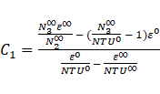
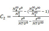
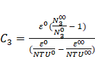
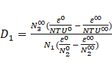
The evaluation of C and D for the Correlation of T*h,o(t) under different MR:
The
correlations for the ratio of ![]() (t) to
(t) to ![]() corresponding to each mass flow step change are as follows:
corresponding to each mass flow step change are as follows:


The generalized form of the above equations is as follows:
The values of C and D from Equations 1 to 3 are shown in Table 4.
Table 4: The values of C and D for equation ![]() (t) under MR
(t) under MR
|
Mass flow rate step |
MR |
C |
D |
|
20g/s to 30g/s |
1.5 |
0.150 |
0.0496 |
|
20g/s to 40 g/s |
2.0 |
0.180 |
0.0500 |
|
20g/s to 50 g/s |
2.5 |
0.315 |
0.0501 |
The
relationship of MR with C in the correlation of ![]()
![]() is illustrated
in Figures 20 and 21 as follow:
is illustrated
in Figures 20 and 21 as follow:
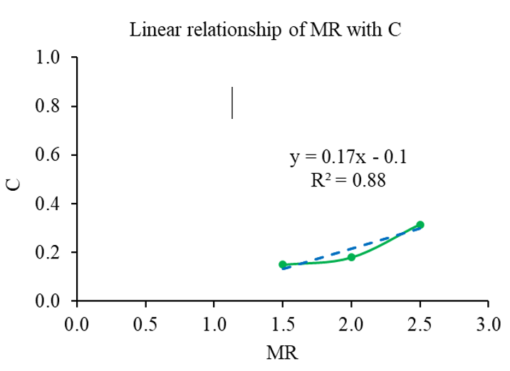
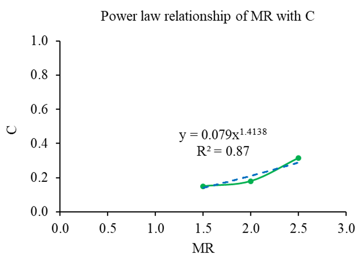
The relationship between MR and C is taken from the best curve fit with R2 value of 0.88, which follows Linear relationship as:
D is averaged 0.05 for all mass flow step changes.