Journal of Fluid Flow, Heat and Mass Transfer (JFFHMT)
ISSN: 2368-6111

Volume 8 - Year 2021 - Pages 166-177
DOI: 10.11159/jffhmt.2021.019
Design and Analytical Evaluation of a Swirler-Injector System
Arash Mousemi1, Sepehr Mosadegh2, Alireza Khademi2
, Giancarlo Sorrentino3
1University of British Columbia, Department of Mechanical Engineering
University Blvd, Vancouver, BC, Canada V6T 1Z4
arash.mousemi@alumni.ubc.ca
2Sharif University of Technology, Department of Aerospace Engineering
Azadi Ave, Tehran, Iran P.O. Box 11365-11155
sepehr.mosadegh@ae.sharif.edu; khademi_alireza@ae.sharif.edu
3University of Naples, Department of Chemical, Materials and Industrial Production Engineering
P. le Tecchio 80, Naples, Italy 80125
g.sorrentino@unina.it
Abstract - Combustion chambers operating with liquid fuels are one of the main components in propulsion systems and power generation units. Designing a high-efficiency burner could provide the opportunity of operating in an environment-friendly regime with a desirable performance. Current literature on burner design highlights that there is no coupled design procedure for the fuel injector and the swirler. This study aims to address the lack of connection between the semi-empirical design algorithms of a pressure-swirl injector and an axial swirler. For this purpose, a novel design algorithm is proposed which utilizes the length of the recirculation zone as the key parameter to link the design procedure of the swirler and the injector. In order to complete the link, Maximum Entropy Formalism (MEF) is used to predict the injection characteristics, e.g., diameter distribution and the velocity of the fuel droplets; thus, provides a rational to confirm the injector design. The proposed idea could be used to design any burner consists of an injector and a swirler.
Keywords: Swirler-Injector system, Liquid fuels, Combustion chamber, Burner, Analytical evaluation.
© Copyright 2021 Authors - This is an Open Access article published under the Creative Commons Attribution License terms Creative Commons Attribution License terms. Unrestricted use, distribution, and reproduction in any medium are permitted, provided the original work is properly cited.
Date Received: 2020-12-16
Date Accepted: 2020-12-18
Date Published: 2021-03-09
Nomenclature
1. Introduction
The fulfillment of several needs in the aviation and energy conversion industries is currently faced with several constraints that are continuously changing the possible scenarios of the near future energy market.
The increasing share of renewable energy with a drastic reduction of greenhouse gas emissions requires the development of reliable burner systems that simultaneously realize the flexibility, high efficiency and very low pollutant emissions [1]. In this context, the assembly and proper design of injector and swirler are essential steps in new burner conceptions because they affect the stabilization and performance of the flame in the expected operation zone. Pressure-swirl injectors are frequently utilized in various combustion systems and are one of the most common types of atomizers due to their simplicity [2]. Liquid fuel is fed to the atomizer via tangential entry ports which induce a centrifugal force to the fluid flow and result in the generation of a gas-core vortex in the atomizer [3]. Therefore, fuel exits from the injector in form of a hollow cone and then breaks into smaller ligaments, and finally droplets.
There are several theoretical and experimental models available on this kind of atomization technique [4]. Lacava et al. [5] proposed an algorithm for the design of pressure-swirl atomizers and validated this algorithm with experimental data. Bazarov and Yang [6] studied the dynamics of the pressure-swirl atomizers of the liquid-propellant rocket engine. Sumer et al. [7] investigated the structure of the flow inside a pressure-swirl atomizer with both experimental techniques and computational fluid dynamics (CFD) tools. The research of Couto et al. [8] revealed a theoretical formulation for predicting the Sauter Mean Diameter of droplets produced by the pressure-swirl injectors.
Axial swirlers are prevalently utilized in the aero-engines to stabilize the flame by inducing an adverse pressure gradient that results in the creation of a recirculation zone in the primary section of the combustion chamber [9]. The strength of the induced swirl is required to be higher than a minimum value to ensure the flame stability. Meanwhile, the air that is fed to the combustor through the swirler collaborates on the cooling of the liner walls. Therefore, the detailed design of the swirlers plays a crucial role in the performance of combustion chamber. Some studies have been performed on determining the working principles of swirlers [10, 11]. Moreover, Lilley [12] experimentally investigated the performance of flat-vanned axial swirlers.
The major limitation of the studies reviewed in this work is the lack of reciprocal interrelation between the design methodology of injector and swirler. Indeed, the performance of these two components are highly depended on each other. In this study, we introduce an algorithm for the design of burner as an integrated system. This technique consists of a design method for pressure-swirl injectors and a prediction for the distribution of velocities and diameters of fuel droplets generated by the atomizer via Maximum Entropy Formalism (MEF). In addition, a procedure for the design of axial swirlers is obtained based on the characteristics of the injector. Then, in this algorithm, the injector is redesigned according to the performance parameters of the achieved swirler, and this cycle is repeated up to an optimal point where the geometrical parameters of the designed burner system converge.
2. Technical Data of the Combustion Chamber
Operative conditions and geometrical parameters of the combustion chamber have essential roles in determining the designing criteria of the injector and swirler. Indeed, the burner system must be conceived after the preliminary design of the combustor which specifies the information about its sizing, air partitioning, total pressure loss in the combustion chamber and temperature of primary zone as input data required for the algorithm proposed in this paper. The algorithm is applied in order to design the burner system that used in an annular Kerosene-burning combustion chamber with the technical characteristics summarized in Table 1.
Table 1. Characteristics of the combustor that are related to the burner design.
| Combustor Reference Area | 0.3135 m2 |
| Liner Diameter | 15.13 cm |
| Liner outer wall diameter | 61.3 cm |
| Air mass flow rate for all swirlers | 1.356 kg/s |
| Fuel mass flow rate for all injectors | 0.3168 kg/s |
| Pressure Loss Factor | 20 |
| Total pressure of the flow exiting from compressor | 7 bar |
| Static pressure of the flow exiting from compressor | 6.785 bar |
| Temperature in primary zone | 1800 K |
| Combustor Reference Area | 0.3135 m2 |
| Liner Diameter | 15.13 cm |
Before describing the method of designing the injector and swirler, it is crucial to decide on the number of burners employed in the combustor, which can be determined by [13]:
Where Dft and Dft,2 are represented in Figure 1. This correlation implies that the distance between two adjacent burners should be taken as near as possible to the distance of the liner walls to the center of the injectors. So, the liquid cone would be able to propagate to the farthest distances in downstream direction without impacting neither liner walls nor neighboring fuel cone jets.
Consequently, the mass flow rate of the air passing through each swirler and the flow rate of the fuel entering each injector should be obtained by dividing the total mass flow of air and fuel by the number of the burners.
3. Design of Pressure-Swirl Injector
To design a pressure-swirl injector, the geometrical parameters represented in Figure 2 are needed to be determined. In the current study, the duty of the injector is assumed to be the production of desired distribution for diameters as well as axial and radial velocities of the droplets to ensure that all of them would be evaporated in the recirculation zone and take part in combustion. The spray cone semi-angle (θ) suggests an interrelation between the axial and radial components of the droplet velocities, and in section 6, a relation between this parameter and the diameter of the swirler is introduced. However, at the first step, the swirler diameter is unknown, hence, we chose 45o as the initial value of the spray cone semi-angle to start the design procedure. The magnitude of this angle is crucial for the residence time of the droplets in the primary zone, and is linked to the desired distribution of droplet sizes.
In the next stage, the proper value for Ls/Ds which commits to two competing effects should be chosen. It is essential to opt for a value that is high enough to stabilize the flow. This stabilization results in the generation of a uniform vortex sheet, nonetheless, the pressure loss in the atomizer will be increased by increasing this ratio [5]. Elkotb et al. [14] suggested that 1 is an appropriate value for this parameter, and in the procedure of designing burner system, this recommended value for Ls/Ds is selected. Furthermore, a proper value is required to be assigned to L0/D0 as another dimensionless geometrical parameter. This ratio is needed to be as small as possible to minimize the friction loss, and is set to unity as recommended in [5]. Two other main parameters which are Ap/(Ds D0) and Ds/D0, have important roles in the algorithm of injector design, and appropriate ranges have been suggested for each of them in the literature. Lefebvre [15] proposed ranges from 0.19 to 1.21 and from 1.41 to 8.13 for Ap/(Ds D0) and Ds/D0, respectively. By finding the value of D0 and the aforementioned dimensionless parameters, all of the geometrical characteristics needed for the design of the injector are determined. Hence, the purpose of the rest of this section is to specify appropriate values for each one of these parameters which result in the desired SMD for the droplets generated by the injector.
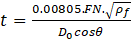
The effective flow area in the injector is characterized by flow number which is a key parameter for calculating the value of geometrical unknowns, and it is defined in Eq. (2) [2].

In order to proceed, D0 should be specified, so, an initial guess is needed to be made for this parameter, and modified until the desired SMD is achieved. A value is assigned to D0 in each iteration, and by evaluating this variable, discharge coefficient which stands for the pressure losses aroused in the nozzle flow passages and the effective cross-sectional area occupied by the fuel flow can be calculated. This variable is defined as [16]
Next, X parameter is defined as the ratio between the area of the core air and total area of the discharge orifice. Assuming that all of the pressure difference made by fuel pump turns into dynamic pressure of the fuel jet at the nozzle tip, and using definition brought in Eq. (2), X can be related to other atomizer’s characteristics through Eq. (4) [5].
Using the value obtained for Cd, X and θ, the value of Ap/(Ds D0) is governed by [16]:
For the next step, liquid film thickness at the nozzle tip of the atomizer is estimated by Eq. (6) which is an empirical correlation suggested by Couto et al. [8].
Again, neglecting pressure losses in the injector and knowing the quantity of ΔP, the velocity of liquid sheet at the nozzle tip is given by Eq. (7).

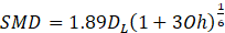
The correlation offered by Couto et al. [8] is employed to find the diameter of the ligaments generated in the primary step of atomization and then Eq. (9) is used for calculating SMD of the droplets formed by the injector.
SMD of the droplets should be equal to or smaller than a desired value, besides, Ap/Ds D0 is preferred to be between 0.19 and 1.21. Hence, we can make use of the value of these parameters as two primary checkpoints for the injector design. In the next section, a theoretical approach is introduced for further characterizing the designed injector, where such performance predictions are employed as criterion for the design procedure.
4. Maximum Entropy Formalism
The design of the atomizer has a crucial constraint which forces the velocity and size of the generated droplets to be small enough in order to guarantee the evaporation of droplets through a finite length in the primary zone of the combustion chamber. This length is related to the design characteristics of the swirler. However, before determining the length of evaporation, it is essential to develop a model for predicting the size and velocity distribution of the droplets. One of the approaches generally used among the researchers is to consider a presumed statistical function such as Rosin-Rammler [17], root-normal [18], log-norm [19], Nukiyama-Tanasawa [20], and log-hyperbolic [21-23] standard functions to predict the distribution of the droplet diameters. Nevertheless, such empirical methods lack universal predictive potential [24].
On the other hand, two analytical methods, including Discrete Probability Function (DPF) and MEF, have been introduced according to the works of Babinsky and Sojka [25] for predicting the distributions. DPF considers droplet generation process as a deterministic primary breakup stage and a nondeterministic secondary breakup phase [26-28] while in MEF, the whole spray formation is contemplated as a nondeterministic phenomenon [29-31]. Reviewing their results, they concluded that DPF is just accurate for the primary atomization, and hence, MEF is selected as our tool for predicting the desired distribution in this work.
In MEF, the information theory is used to characterize the velocity and size distribution of the droplets generated by the injector. The theory proposes that there is a condition in which the entropy of the system reaches its maximum, and results in the distribution with the most possibility under the restriction of constraints applied due to the nature of the phenomena [32]. Shannon [33] proposed the relationship represented in Eq. (10) to set a link between the information entropy and probability distribution.

To show that the probability is a function of droplet size and velocity, pi should be replaced by pij which indicates the probability of having a droplet with diameter of Di and velocity of Vj. Throughout the present work, all the fuel droplets are assumed to be spherical, and their diameters and velocities are normalized by the mass mean diameter (dm) of the droplets and the liquid film velocity in the jet direction at the nozzle exit, respectively.


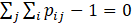
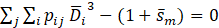
There are some constraints forced by the necessity of number balance, mass balance, momentum balance and energy balance of the droplets. The number balance of the droplets suggests that the summation of the probabilities should be equal to 1 as represented in Eq. (13).
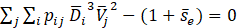
Moreover, the mass, momentum, and energy balance for the droplets impose three following equations [18].
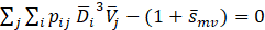
Here ![]() is the dimensionless source-term for mass exchange between the liquid jet and the surrounding gas, and takes care of the fuel evaporation rate at the primary and secondary phases of the liquid film breakup process. In order to simplify the model used for this term and to reach higher reliability for the design algorithm, more critical condition in which droplets have shorter time to be vaporized, and droplet evaporation starts after completion of breakup process is assumed. This assumption implies that the dimensionless mass source-term should be neglected through the rest of this work.
is the dimensionless source-term for mass exchange between the liquid jet and the surrounding gas, and takes care of the fuel evaporation rate at the primary and secondary phases of the liquid film breakup process. In order to simplify the model used for this term and to reach higher reliability for the design algorithm, more critical condition in which droplets have shorter time to be vaporized, and droplet evaporation starts after completion of breakup process is assumed. This assumption implies that the dimensionless mass source-term should be neglected through the rest of this work. ![]() denotes the dimensionless momentum loss of the liquid particles due to the drag force imposed by the surrounding gas inside the combustion chamber. In addition,
denotes the dimensionless momentum loss of the liquid particles due to the drag force imposed by the surrounding gas inside the combustion chamber. In addition, ![]() is the dimensionless energy source-term for balancing the equation of energy conservation, and accounts for the rate at which the liquid particles lose their kinetic energy. This energy is mainly transformed to surface free energy of the liquid droplets, however, some small ratio of that can also be converted to internal energy of the fuel or surrounding gas particles. Besides, momentum exchange between the fuel ligaments and the surrounding gas particles can transfer some ratio of the kinetic energy in liquid phase to the kinetic energy of the gas particles. Nonetheless, much smaller density of the surrounding gas makes this ratio negligible compared to that for transformation to the surface energy. These two source-terms are not small, and need to be modeled. To set a value for
is the dimensionless energy source-term for balancing the equation of energy conservation, and accounts for the rate at which the liquid particles lose their kinetic energy. This energy is mainly transformed to surface free energy of the liquid droplets, however, some small ratio of that can also be converted to internal energy of the fuel or surrounding gas particles. Besides, momentum exchange between the fuel ligaments and the surrounding gas particles can transfer some ratio of the kinetic energy in liquid phase to the kinetic energy of the gas particles. Nonetheless, much smaller density of the surrounding gas makes this ratio negligible compared to that for transformation to the surface energy. These two source-terms are not small, and need to be modeled. To set a value for ![]() the trial-and-error method applied by Mondal et al. [32] is used to achieve a reasonable distribution. Moreover, they suggested Eq. (17) which accounts only for transformation of the kinetic energy to the interfacial free energy of fuel droplets in order to obtain the value of
the trial-and-error method applied by Mondal et al. [32] is used to achieve a reasonable distribution. Moreover, they suggested Eq. (17) which accounts only for transformation of the kinetic energy to the interfacial free energy of fuel droplets in order to obtain the value of ![]() .
.
All of the parameters that appeared on the right-hand side of this equation are determined during the atomizer design procedure.
The discrete summation form of the equations for number, mass, momentum and energy balance can be written in their integral form as
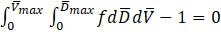
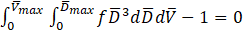

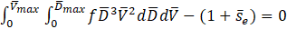
Where f is the joint probability density function (PDF) for the distribution of diameters and velocities of the fuel droplets.
To maximize the entropy of the system, Kim et al. [24] made use of the Lagrange multipliers method [34] and demonstrated that the PDF should be in the form of

Where f0 is the PDF of prior droplet sizes; λ1, λ2, λ3 and λ4. are the Lagrange multipliers which are essential to be calculated for specifying the joint PDF. By substituting the correlation introduced for f (Eq. (22)) into Eqs. (18) to (21), and solving for the multipliers their value, and consequently, the joint PDF can be specified.
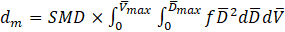
As it was mentioned, the droplet diameters are normalized by dm, and to characterize the distribution of the diameters of the droplets, mass mean diameter is required, which is calculated by [20]
Therefore, the size and velocity distribution for the droplets which is necessary for designing the burner system as an integrated system is obtained. The role of this distribution in the design procedure will be explained in section 6.
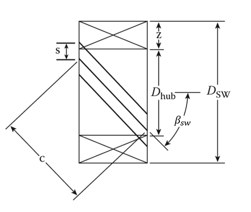
5. Design of Flat-Vane Axial Swirler
To accomplish the preliminary design of a flat-vane axial swirler, the geometrical parameters shown in Fig. 3 are required to be specified. The functionality of the swirler is dependent on the formation of a low-pressure recirculation zone which occurs in highly-swirled flows. Hence, the crucial criteria for designing a swirler is to induce a sufficient swirl to the air passing through it to cause a vortex breakdown in the combustor. Spalding [35] used a dimensionless parameter named Swirl Number (SN) to characterize the amount of swirl imparted to the axial flow, which is defined as

Where Gm is the axial flux of tangential momentum and Gt is the axial flux of axial momentum.
Firstly, an initial value should be fixed for the angle of the swirler vanes with respect to the axial direction (βsw) which is considered to be between 30o and 60o. Moreover, pressure loss factor of the airflow due to the passage through the swirler is needed to be determined. It is suggested to consider the total pressure loss in the swirler equal to 3% to 4% of the total pressure of the air entering the combustion chamber [35-38]. By allocating a value to these parameters, the total area of the swirlers can be calculated by [38]
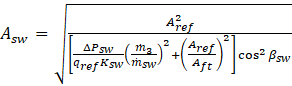
Where the appropriate value for Ksw is 1.3 for a flat-vane swirler and 1.15 for a curved-vane one [35-38].
On the other hand, the area of the swirler is related to the geometrical characteristics of it through Eq. (26).

Here n and δ represent the number of blades used in each swirler and blade thickness, respectively. These parameters are needed to be selected according to the technology of manufacturing. The number of blades is chosen between 8 to 16, and the blade thickness is set between 0.7 mm to 1.5 mm. In addition, having the geometrical characteristics of the injector, we can obtain the value of hub diameter of the swirler by
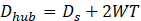
In which WT is the wall thickness of the atomizer. Hence, we can compute the tip diameter of the swirler by solving Eq. (26) for Dtip.
At this stage, having a value been set for βsw, Dhub and Dtip, one can calculate the swirl number of a flat-vane axial swirler by Eq. (28) [35].
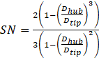
The values of three dimensionless parameters including SN, Dhub/Dt and Dsw/Dft, are the crucial criteria for the design of the swirler. For the definitive appearance of the recirculation zone in the combustor, SN has to be high enough to induce a sufficient amount of swirl which results in the vortex breakdown in the flow field. We opt for SN = 1 as the minimum value required for the swirl number of the swirler, and it is set as one of the benchmarks for designing procedure. Furthermore, the appropriate values for Dhub/Dtip and Dtip/Dft are considered within the ranges of 1/3-2/3 and 0.2-0.6, respectively. Thus, βsw is changed in a repetitive cycle till all of these three non-dimensional parameters fall in the proper range.
After determining the appropriate values of βsw, Dhub, Dt, n and δ, the chord length of the swirler vanes is the only geometrical parameter of this component left unknown, and can be determined using no see-through rule which suggests that the gap between swirler vanes should not be observable by looking at the burner in direction parallel to its axis. Therefore, the chord length can be calculated by
Moreover, the recirculation zone angle (θRZ) which is illustrated in Fig. 4 is related to the features of the swirler with [39]

Where it is suggested to set LRZ equal to 2Dtip [13].
In practice, the characteristics of injector and swirler are interrelated, and they have a considerable impact on the performance of each other. Therefore, obtaining a relationship between the features of these two components in the design procedure of the burner system is essential, and is discussed in the next section.
6. The Procedure of the Burner System
Our aim in this section is to couple the design procedure of injector and swirler and propose a method for designing the whole burner simultaneously. One of the most important characteristics of the injector is the size of the droplets it generates. In section 3, SMD was considered as a representative for the size of the droplets, and an initial value was set as its upper limit. However, the value of this limit should be determined by the characteristics of the swirler and liner. Moreover, the distribution of the diameters and velocities of the droplets which are obtained through the MEF should be considered in the design procedure.
Up to this step, we introduced a preliminary method for the design of injector and swirler, separately. However, the upper limit for SMD should be revised according to the required time for evaporation of the droplets in the primary zone and the time which droplets have before reaching the liner walls. To obtain the value of these two parameters, we should first model the path that droplets travel through, and introduce a model for their evaporation in the combustor. After the primary design of the swirler, the spray cone semi-angle should be revised as
Therefore, the required time for the droplets to travel from the injector nozzle to the combustor walls is calculated via Eq. (32).

On the other hand, Chin and Lefebvre [40] suggested using Eq. (33) for determining the required time for evaporation of a droplet with the initial diameter of D0.

Here λeff denotes the effective evaporation constant for the fuel droplets which takes care of both heat-up and steady-state periods of drop evaporation discussed in [2]. This parameter is a function of the pressure and temperature of the combustor, and velocity of the droplet relative to surrounding air and boiling point of the fuel. The initial temperature of the fuel flow influences the heat-up phase which is of minor importance compared to the steady-state period of evaporation. Therefore, temperature of the entry fuel has much smaller effect on the evaporation time with respect to other parameters studied in [40]. Chin and Lefebvre represented the value of this constant for various conditions [40]. However, due to the complicated flow pattern generated by the recirculation flow, determining the velocity of droplets relative to the surrounding air is difficult. Hence, in the design procedure, the worst case for the evaporation of the droplets is considered which occurred when this relative velocity is equal to zero and thus, the required time for evaporation of the droplets would be maximized. Therefore, the value of SMDd is modified for the next iteration by considering the evaporation time.
By determining the modified values of SMDd and θ for the injector, all of the procedures for design of injector and swirler are repeated until the magnitude of the swirler tip diameter converges to a specific value. Nevertheless, the desired SMD we introduced up to this point will guarantee the evaporation of all the droplets generated by the injector. Thus, the distribution of sizes and velocities of the droplets obtained in section 4 should be used to ensure that our design is appropriate for evaporation of all the droplets.
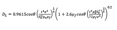
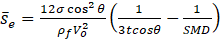
To do so, the droplet diameter which is higher than the size of 90% of the droplets (D90) and the velocity of the droplet which is higher than the velocity of 90% of them (V90), are calculated through the joint PDF specified by MEF. The length that a droplet with the diameter of D90 and velocity of V90 required to evaporate in the combustor is calculated by
This length has to be smaller than the length that droplets travel to reach the liner walls, which can be described as

If Le > Lr, we should reduce SMDd and repeat all of the procedures introduced in sections 3, 4 and 5 for the design of injector and swirler and continue the cycle till Le becomes smaller than Lr [41].
The flowchart of the burner system design is presented in Fig. 5.
5. Discussion and Conclusion
To evaluate the developed methodology established in this paper for the design of burner system, we applied this procedure to design a burner system for the combustor with characteristics introduced in section 2. The results of the geometrical parameters of the injector and swirler are summarized in table 2. In addition, the PDF for the diameters and velocities of the droplets is illustrated in Fig. 6. The shape of PDF represents that the majority of the fuel droplets have velocities and diameters which are near to the mean values, and the probability of finding a droplet with a diameter 3 times bigger than the mean value is negligible.
Table 2. Design parameters for the burner.
| Nbu | 10 |
| θ | 32.34o |
| ΔP | 4 bar |
| SMD | 37.12 μm |
| D0 | 3.5 mm |
| Ds | 2.8 cm |
| Ap/(Ds D0) | 0.1978 |
| Ds/D0 | 7.99 |
| t | 0.136 mm |
| np | 2 |
| Dp | 3.5 mm |
| δ | 0.7 mm |
| β | 52o |
| n | 12 |
| Dtip | 5.97 cm |
| Dhub | 3.1 cm |
| SN | 1.017 |
| 0RZ | 33.01 o |
| Dhub/Dtip | 0.546 |
| Dtip/Dft | 0.395 |
| c | 1.98 cm |
In the context of low-NOx combustion systems, the present study introduced an optimization procedure coupled with a design algorithm for pressure-swirl injectors and a prediction for the distribution of velocities and diameters of fuel droplets generated by the atomizer via Maximum Entropy Formalism (MEF). Moreover, a procedure for the design of axial swirlers was obtained based on the characteristics of the injector. Then, in this algorithm, injector was redesigned according to the performance parameters of the achieved swirler, and this cycle was repeated up to an optimal point where the geometrical parameters of the designed burner system converge. The injector and swirler conceptions were coupled to the whole burner design simultaneously. Moreover, the distribution of the diameters and velocities of the droplets which were obtained through the MEF were considered in the design procedure. All of the equations were extracted from publications with numerical or experimental verification. Future improvements of the model will require validation data to prove the functionality of the designed system.
In the context of low-NOx combustion systems, the present study introduced an optimization procedure coupled with a design algorithm for pressure-swirl injectors and a prediction for the distribution of velocities and diameters of fuel droplets generated by the atomizer via Maximum Entropy Formalism (MEF). Moreover, a procedure for the design of axial swirlers was obtained based on the characteristics of the injector. Then, in this algorithm, injector is redesigned according to the performance parameters of the achieved swirler, and this cycle is repeated up to an optimal point where the geometrical parameters of the designed burner system converge.
Operative conditions and geometrical parameters of the combustion chamber have an essential role in determining the designing criteria of the injector and swirler. Indeed, the burner system must be conceived after the preliminary design of combustor which specifies the information about its sizing, air partitioning, total pressure loss in the combustion chamber and temperature of primary zone as input data required for the algorithm proposed in this paper.
We applied this procedure to design the burner system utilized in an annular Kerosene-burning combustion chamber with specific features. The design of a flat-vane axial swirler was dependent on the formation of a low-pressure recirculation zone, which occurred in highly-swirled flows. Hence, the crucial criteria for designing a swirler was to induce a sufficient swirl to the air passing through it to cause a vortex breakdown in the combustor. The injector and swirler conceptions were coupled to the whole burner design simultaneously. One of the most important characteristics of the injector is the size of the droplets it generates. However, the value of this limit should be determined by the characteristics of the swirler and liner. Moreover, the distribution of the diameters and velocities of the droplets which were obtained through the MEF were considered in the design procedure.
Therefore, the results of this study were the design methodology for a burner system and the optimization of a Maximum Entropy Formalism (MEF) to obtain the distribution of velocities and diameters of the fuel droplets. All of the equations were extracted from publications with numerical or experimental verification. Future improvements of the model will require validation data to prove the functionality of the designed system.
References
[1] IEA, P. “Energy technology perspectives 2012: Pathways to a clean energy system." International Energy Agency Paris, 2012. View Article
[2] Lefebvre, A. H., and Ballal, D. R. Gas turbine combustion: alternative fuels and emissions: CRC press, 2010. View Article
[3] Chen, X., and Yang, V., “Effect of ambient pressure on liquid swirl injector flow dynamics," Physics of Fluids Vol. 26, No. 10, 2014, p. 102-104. View Article
[4] Ipp, W., Wagner, V., Krämer, H., Wensing, M., Leipertz, A., Arndt, S., and Jain, A. K., “Spray formation of high pressure swirl gasoline injectors investigated by two-dimensional Mie and LIEF techniques," SAE Technical Paper Series , 1999, pp. 503-515. View Article
[5] Lacava, P. T., Bastos-Netto, D., and Pimenta, A. P. “Design procedure and experimental evaluation of pressure-swirl atomizers," 24th international congress of the aeronautical science. 2004.
[6] Bazarov, V. G., and Yang, V., “Liquid-propellant rocket engine injector dynamics," Journal of Propulsion and Power, Vol. 14, No. 5, 1998, pp. 797-806. View Article
[7] Sumer, B., Erkan, N., Uzol, O., and Tuncer, I., “Experimental and numerical investigation of a pressure swirl atomizer," Proceedings of 12th ICLASS Conference. Ilass Europe Heidelberg, Germany, 2012.
[8] Couto, H., Carvalho, J., and Bastos-Netto, D., “Theoretical formulation for Sauter mean diameter of pressure-swirl atomizers," Journal of Propulsion and power, Vol. 13, No. 5, 1997, pp. 691-696. View Article
[9] Fu, Y., Jeng, S.-M., and Tacina, R., “Characteristics of the swirling flow generated by an axial swirler,” ASME Turbo Expo 2005: Power for Land, Sea, and Air. American Society of Mechanical Engineers Digital Collection, 2005, pp. 517-526. View Article
[10] Hegde, G. B., Khandelwal, B., Sethi, V., and Singh, R., “Design, evaluation and performance analysis of staged low emission combustors,” ASME Turbo Expo 2012: Turbine Technical Conference and Exposition. American Society of Mechanical Engineers, 2012, pp. 867-875. View Article
[11] Fu, Y., Jeng, S.-M., and Tacina, R., “Confinement effects on the swirling flow generated by a helical axial swirler,” 44th AIAA Aerospace Sciences Meeting and Exhibit. 2006, p. 545. View Article
[12] Lilley, D. G., “Annular vane swirler performance,” Journal of Propulsion and Power Vol. 15, No. 2, 1999, pp. 248-252. View Article
[13] Research, N., Corporation, E., and Melconian, J. O. The Design and Development of Gas Turbine Combustors: Northern Research and Engineering Corporation, 1980.
[14] Elkotb, M., Rafat, N., and Hanna, M., “The influence of swirl atomizer geometry on the atomization performance,” Proceedings of the 1st International Conference on Liquid Atomization and Spray Systems. 1978, pp. 109-115.
[15] Lefebvre, A. H., and McDonell, V. G. Atomization and sprays: CRC press, 2017. View Article
[16] Chinn, J. J., “An Appraisal Of Swirl Atomizer Inviscid Flow Analysis, Part 1: The Principle Of Maximum Flow For A Swirl Atomizer And Its Use In The Exposition And Comparison Of Early Flow Analyses.” Atomization and Sprays, Vol. 19, No. 3, 2009, pp. 263–282. View Article
[17] Rosin, P., and Rammler, E. "The laws of governing the fineness of powdered coal. J Inst Fuel 7: 29–36." 1933.
[18] Tate RW, Marshal Jr. WR. Atomization by centrifuga pressure nozzles, Chem Engng Prog 1953;49:169-74
[19] Crow EL, Shimizu K. Lognormal distributions: theory and applications. New York: Marcel Dekker, 1988
[20] Nukiyama S, Tanasawa Y. Experiments on the atomization of liquids in an air stream. Report 3: on the droplet-size distribution in an atomized jet. Trans Soc Mech Engrs Jpn 1939;5:627. View Article
[21] Bhatia, J. C., Dominick, J., Durst, F., Tropea, C., “Phase-doppler-anemometry and the log-hyperbolic distribution applied sprays,” Particle & Particle Systems Characterizaton, Vol. 5, No. 4, 1988, pp. 153-164. View Article
[22] Bhatia, J. C., and Durst, F., “Comparative study of some probability distributions applied to liquid sprays,” Particle & Particle Systems Characterizaton, Vol. 6, No. 1-4, 1989, pp. 151-162. View Article
[23] Bhatia, J. C., and Durst, F., “Description of sprays using joint hyperbolic distribution in particle size and velocity,” Combustion and Flame, Vol. 81, No. 3-4, 1990, pp. 203-218. View Article
[24] Kim, W. T., Mitra, S. K., Li, X., Prociw, L., and Hu, T., “A predictive model for the initial droplet size and velocity distributions in sprays and comparison with experiments,” Particle & Particle Systems Characterization: Measurement and Description of Particle Properties and Behavior in Powders and Other Disperse Systems,Vol. 20, No. 2, 2003, pp. 135-149. View Article
[25] Babinsky, E., and Sojka, P., “Modeling drop size distributions,” Progress in energy and combustion science, Vol. 28, No. 4, 2002, pp. 303-329. View Article
[26] Sovani, S. D., Sojka, P. E., Sivathanu, Y. R., “Prediction of drop size distributions from first principles: the influence of fluctuations in relative velocity and liquid physical properties,” Atomization and Sprays, Vol. 10, No. 6, 2000, pp. 16. View Article
[27] Sovani, S. D., Sojka, P. E., Sivathanu, Y. R., “Prediction of drop size distributions from first principles: joint PDF effects,” Atomization and Sprays, Vol. 9, No. 2, 1999, pp. 16. View Article
[28] Sivathanu, Y. R., and Gore, J. P., “A discrete probability function method for equation of radiative transfer,” Journal of Quantitative Spectroscopy and Radiative Transfer, Vol. 49, No. 3, 1993, pp. 269–280. View Article
[29] Sellens RW, Brzustowski TA. A prediction of drop size distribution in a spray from first principles. Atom Spray Technol 1985;1:89-102.
[30] Xianguo, L., and Tankin, R., “Droplet Size Distribution: A Derivation of a Nukiyama-Tanasawa Type Distribution Function,” Combustion Science and Technology, Vol. 56, No. 1, 1987, pp. 65–76. View Article
[31] Cousin, J., Yoon, S. J., Dumouchel, C., “Coupling the classical linear theory and maximum entropy formalism for prediction of drop size distribution in sprays: application to pressure-swirl atomizers,” Atomization and Sprays, Vol. 6, No. 5, 1996, pp. 601–622. View Article
[32] Mondal, D., Datta, A., and Sarkar, A., “Droplet size and velocity distributions in a spray from a pressure swirl atomizer: application of maximum entropy formalism,” Proceedings of the Institution of Mechanical Engineers, Part C: Journal of Mechanical Engineering Science, Vol. 218, No. 7, 2004, pp. 737-749. View Article
[33] Shannon, C. E., “A mathematical theory of communication,” Bell system technical journal, Vol. 27, No. 3, 1948, pp. 379-423. View Article
[34] Jupp, P.E., Levine, R. D., and Tribus, M., “The maximum entropy formalism,” Biometrics, Vol. 35, No. 4, 1979, pp. 902. View Article
[35] Spalding, D.B., “Combustion aerodynamics,” Journal of Fluid Mechanics, Vol. 54, No. 4, 1972, pp. 762. View Article
[36] Mathur, M., and NR, M., “Swirling air jets issuing from vane swirlers. 1. Free jets,” Journal of the Institute of Fuel, Vol. 40, No. 316, 1967, pp. 214-&.
[37] Kilik, E. "The influence of swirler design parameters on the aerodynamics of downstream recirculation region,” 1976.
[38]Knight, H., and Walker, R. "THE COMPONENT PRESSURE LOSSES ON COMBUSTION CHAMBERS. ” NATIONAL GAS TURBINE ESTABLISHMENT FARNBOROUGH (UNITED KINGDOM), 1953.
[39] Conrado, A. C., and Lacava Filho, P., “ACP and Sanchez MS, Basis Design Principles for Gas Turbine Combustor,” Proc. of the 10 th Brazilian Congress of Thermal Science and Engineering, Rio de Janeiro. 2004.
[40] Chin, J., and Lefebvre, A., “Effective values of evaporation constant for hydrocarbon fuel drops,” Proceedings of the 20th Automotive Technology Development Contractor Coordination Meeting, 1982, pp. 325-331.
[41] A. Mousemi, S. Mosadegh, A. Khademi, G. Sorrentino, Design Algorithm Evaluation of Swirler-Injector Systems in Liquid-Burning Combustion Chambers, Proceedings of the 7th International Conference on Fluid Flow, Heat and Mass Transfer (FFHMT'20), 2020. View Article