Journal of Fluid Flow, Heat and Mass Transfer (JFFHMT)
ISSN: 2368-6111

Volume 8 - Year 2021 - Pages 153-158
DOI: 10.11159/jffhmt.2021.017
An Experimental Study with Condenser Embedded Adsorber of an Adsorption Chiller
Gamze Gediz Ilis1, Hasan Demir2
1Gebze Technical University, Mechanical Engineering Department,
Gebze, Kocaeli, Turkey 41400
ggedizilis@gmail.com; ggediz@gtu.edu.tr
2Osmaniye Korkut Ata University, Chemical Engineering Department,
Osmaniye, Turkey 80000
demirhasan.hd@gmail.com
Abstract - In this paper, in order to increase the adsorption chiller performance a new type adsorbent bed with embedded condenser is designed and constructed. By this condenser embedded adsorbent bed design, not only the performance increase but also the weight reduction of the adsorption chiller is achieved. Experiments were performed with Silica gel RD type adsorbent and water pair. The experiments were performed, and the results are given for the novel adsorption chiller. The average adsorbent bed temperatures and concentration changes for adsorption/desorption processes for the specified conditions are measured and shared in this paper.
Keywords: adsorption, embedded condenser, heat and mass transfer, experimental.
© Copyright 2021 Authors - This is an Open Access article published under the Creative Commons Attribution License terms Creative Commons Attribution License terms. Unrestricted use, distribution, and reproduction in any medium are permitted, provided the original work is properly cited.
Date Received: 2020-10-22
Date Accepted: 2020-10-27
Date Published: 2021-03-03
1. Introduction
In last 40 years, many articles have been published about adsorption cooling topic. Approximately half of these studies are published in the last five years [1]. This phenomenon indicates that importance environmentally friendly systems which is alternative to the conventional heat pump due to operating non-hazardous refrigerants and provide cooling effects using thermal energy sources is understood by researchers.
Studies on adsorption heat pumps can be focused on solar refrigerator and ice makers, advanced cycles, material improvement, and consolidated beat materials. Researchers focused on improving novel adsorbent bed design for increasing heat transfer rate thus increasing the Specific Cooling Performance (SCP) and COP of the adsorption chiller [2]. Mohammed et al. [3] increased performance indicators of adsorption heat pump system placing silica gel particles in a high-porosity aluminium foam which is the example of consolidated materials. Zhao et al. [4] worked on eliminating performance delay of the solar adsorption refrigeration with finned tubes. The fins affected on the thermal performance of the system and the temperature distribution of activated carbon around the finned tube is found out more uniform than the smooth tube of the system [4]. Mohammed et al.[5], constructed repeated packed bed modules and each module has sub-modules which are separated by 2mm metal walls and trays. Silica gel RD-2060 and AQSOA-Z02 zeolite are used as adsorbents in the systems. The SCP of system with silica gel RD-2060 showed higher than that of system with AQSOA-Z02 zeolite. Ilis et al. [6], simulated star fin type consolidated adsorbent bed with addition of aluminium particles for enhancing effective thermal conductivity of bed. The addition of aluminium particles improved SCP with 300% of increment.
Although, as mentioned above, the modification can increase the heat transfer rate in the adsorbent bed, commercialization of adsorption chiller is not sufficiently widespread. In the present paper, the manufactured adsorbent bed and its evaporator consisting many tubes is constructed. The Fuji type RD silica gels are placed inside the tubes providing rapid heat transfer rate during heating and cooling periods of cycles. In the shell side of adsorption chiller, cooling/heating water is circulated. The desorbed water from adsorbents condenses inside the adsorbent bed rather than condenser during isobaric desorption process. This condensed water inside the adsorbent bed reduces the water evaporation amount and chilled effect of adsorption chiller. In this work, combining condenser and adsorbent bed parts of adsorption chiller in an equipment is firstly tried. The performance of new combined condenser-adsorbent bed is investigated experimentally.
2. Experimental Study
2. 1. Designed Setup
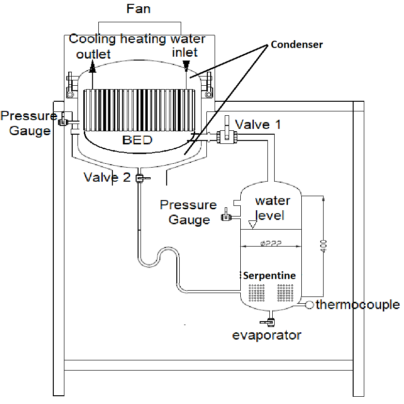
The constructed experimental setup was made of stainless-steel (type 304) and its components are shown in Fig. 1. The setup had two main components; an adsorbent bed and an evaporator. A steel frame is used to fix the adsorbent bed and evaporator. The evaporator is filled with water. The evaporator had a volume of 16 lt and the sight glass mounted to observe the level of water. A thermocouple is located inside of the evaporator. A serpentine heat exchanger is located inside the evaporator to transfer heat to the water. A desired water temperature is gained by fixing the temperature of water inside the evaporator by this heat exchanger. The temperature of the water circulating inside of the serpentine heat exchanger is measured at the inlet and the outlet during the evaporation and observed a decrease inside of the water vessel. A vacuum tight valve is mounted between the adsorbent bed and evaporator.
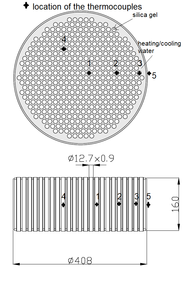
The significance of this study is the design of the adsorbent bed where the condenser is located inside of the bed not as another component. The adsorbent bed having 408 mm inner diameter, height of 160 mm consists of 444 pipes (Pipe diameter is = 12.7 mm with 0.9 mm stainless steel thickness) as shown in Fig. 1. The outer case of adsorbent bed is used as condenser area. The condenser is cooled by air with air fan. Condensed water gathered bottom the adsorbent bed between case of shell and tubes and outer case of bed. Condensed water transferred to evaporator with opening valve 2 without pressure changed. The pressure change is prevented using S shape capillary tube between condenser and evaporator. The adsorbent bed is similar with shell and tubes heat exchangers. On the tubes side, silica gel particles are filled and on the shell side, cooling/heating water is circulated. Totally 4.65 kg silica gel RD supplied from Fuji Slysia Chemical Co., is placed among the pipes. The properties of silica gels are listed in Table 1. The water vapor from evaporator enters on the bottom of adsorbent bed which is separated from condenser with concave case for leading water vapor through the tubes. The circulating cooling-heating water inlets and outlets are illustrated in Fig. 1. The locations of the thermocouples are marked on the adsorbent bed in Fig.1. There are five star-mark (#1-5) on the bed which are used in order to measure the adsorbent bed average temperature (#1-4) and surface temperature (#5). The thermocouples (#1-4) are located inside of the silica gel and measured the temperature of the silica gel thus the bed average temperature.
The constructed experimental setup was made of stainless-steel (type 304) and its components are shown in Fig. 1. The setup had two main components; an adsorbent bed and an evaporator. A steel frame is used to fix the adsorbent bed and evaporator. The evaporator is filled with water. The evaporator had a volume of 16 lt and the sight glass mounted to observe the level of water. A thermocouple is located inside of the evaporator. A serpentine heat exchanger is located inside the evaporator to transfer heat to the water. A desired water temperature is gained by fixing the temperature of water inside the evaporator by this heat exchanger. The temperature of the water circulating inside of the serpentine heat exchanger is measured at the inlet and the outlet during the evaporation and observed a decrease inside of the water vessel. A vacuum tight valve is mounted between the adsorbent bed and evaporator.
The significance of this study is the design of the adsorbent bed where the condenser is located inside of the bed not as another component. The adsorbent bed having 408 mm inner diameter, height of 160 mm consists of 444 pipes (Pipe diameter is = 12.7 mm with 0.9 mm stainless steel thickness) as shown in Fig. 1. The outer case of adsorbent bed is used as condenser area. The condenser is cooled by air with air fan. Condensed water gathered bottom the adsorbent bed between case of shell and tubes and outer case of bed. Condensed water transferred to evaporator with opening valve 2 without pressure changed. The pressure change is prevented using S shape capillary tube between condenser and evaporator. The adsorbent bed is similar with shell and tubes heat exchangers. On the tubes side, silica gel particles are filled and on the shell side, cooling/heating water is circulated. Totally 4.65 kg silica gel RD supplied from Fuji Slysia Chemical Co., is placed among the pipes. The properties of silica gels are listed in Table 1. The water vapor from evaporator enters on the bottom of adsorbent bed which is separated from condenser with concave case for leading water vapor through the tubes. The circulating cooling-heating water inlets and outlets are illustrated in Fig. 1. The locations of the thermocouples are marked on the adsorbent bed in Fig.1. There are five star-mark (#1-5) on the bed which are used in order to measure the adsorbent bed average temperature (#1-4) and surface temperature (#5). The thermocouples (#1-4) are located inside of the silica gel and measured the temperature of the silica gel thus the bed average temperature.
2. 2. Experimental Procedure
Firstly, the water vessel which is worked as evaporator as well is filled 12 lt deionized water. It is evacuated from air inside and the pressure of water vessel is reduced to the set pressure of the adsorption process by using a vacuum pump. Then, the adsorbent bed is evacuated by heated water at 85oC (by circulation water) in order to remove water content and other gases in the silica gel particles.
Secondly, the bed temperatures are stabilized to the desired initial temperature (45oC adsorbent bed temperature). In the third step, the adsorption process is started by opening the valve 1 between water vessel and adsorbent bed. The evaporated water in the vessel is started to be flow into the adsorbent bed and adsorbed by silica gel granules. During the adsorption process (⁓3.5 kPa), the cooling water is started to be circulated and let it to fill the adsorbent bed in order to cool it down. The cooling of adsorbent bed is done by cooling water circulated from the outer surface of the silica gel filled tubes. The water level inside of the evaporator is marked in certain time intervals. By this method, the evaporated water amount is measured. The isobaric adsorption process is continued until the level of water inside the water vessel is not changed. During the adsorption/desorption processes, the temperatures at different locations of the bed are measured (Fig.1). At the end of the adsorption, the valve 1 between the adsorbent bed and the water vessel is closed. These pressure gauges have ±0.4% accuracy. All thermocouples are calibrated (Fluke 714 temperature calibrator with 0.025% accuracy). The response time of the K type thermocouples is 0.5 sec. After adsorption period, the heated (85oC) water is started to be circulated in order to increase the pressure inside of the bed. When it reaches the desired pressure (⁓6.5 kPa), the fan is started which has power 100W. The valve 2 between the water vessel and the bed is opened when the temperature of the bed reaches 85oC. The water vapor started to remove from the silica gel and desorption starts at this stage. The unity of the bed is at this part; the condensation occurs on outer case of adsorbent bed cooling with air fan circulation. The condensations start over the surface of the adsorbent bed and the condensed water started to fill the evaporator. With the same method, the level of the water is measured in order to observe the condensation rate. The valve 2 is closed when the condensation ends means no elevation change inside of the evaporator.
3. Results and Discussion
In this section, by using the designed experimental setup and adsorbent bed, the experimental results are explained in detail. The average bed temperature and pressure during all processes of cycle are shown in Fig.2. In the isobaric adsorption process (d-a), the average bed temperature immediately jumped to 70oC as well as open the valve between evaporator and adsorber. Dash line indicating bed pressure in the adsorber almost constant as expected in the adsorption process called as isobaric process ideally. During isosteric heating process (a-b), both adsorbent bed temperature and pressure increase without any desorption of water from silica gels. In the desorption process (b-c), the average adsorbent bed pressure increased gradually meanwhile the bed pressure reduces which should be constant during process ideally. This phenomenon indicates that the condensation of adsorptive happened adequately due to low surface area of condenser. The duration of isosteric heating (b-a) and cooling (c-d) are not too long and most of cycle time is consumed for the processes of isobaric adsorption (d-a) and isobaric desorption (b-c) due to poor heat transfer in the bed.
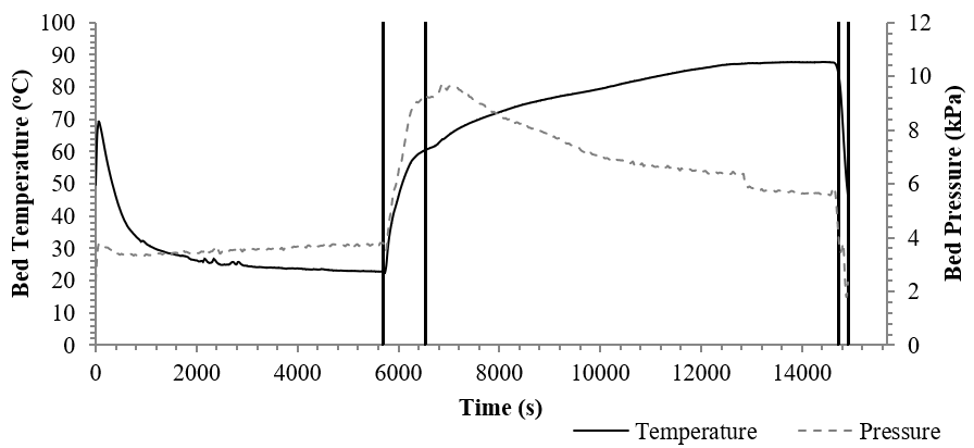
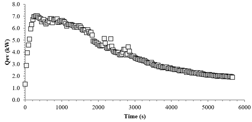
Fig. 3. illustrates transferred heat instantaneously from heat exchanger fluid to adsorptive in isobaric adsorption process in evaporator. At the beginning of the isobaric adsorption period, power of evaporator increased rapidly due to high adsorption rate. Afterward power started to decrease because of falling adsorption rate. Area under the curve (Fig. 3) denotes the total power of evaporator was generally increases with increasing operation time.
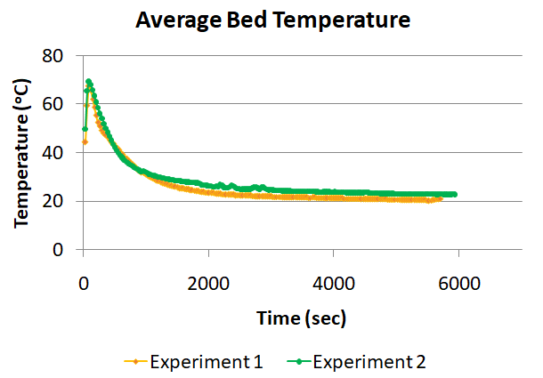
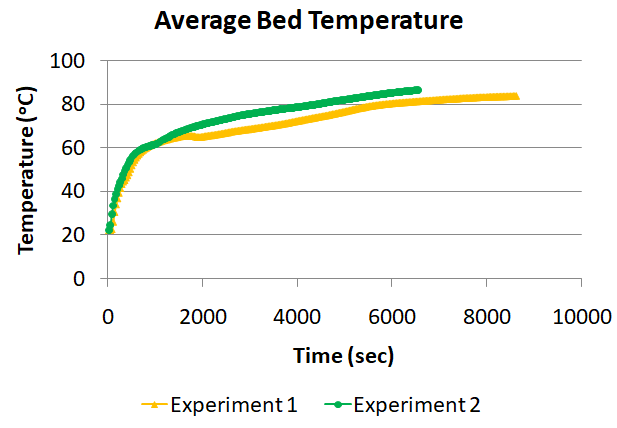
As mentioned, the experiments are started when the adsorbent bed temperature is around 45oC and during adsorption, the bed is cooled by water at 20oC surrounded the pipe filled with silica gel (Fig. 4(a)). After adsorption, the bed is started to be heated by 85oC water (Fig.4(b)). Both the average bed temperature and the percentage of water adsorbed / desorbed during the adsorption and desorption periods. The evaporator is at around 25oC initially at the beginning of the adsorption process.
The average adsorbent bed temperatures reach up to around 70oC (Fig. 4(a)) during the adsorption process due to heat of adsorption and then decreases to cooling water temperature. The desorption process comparison is also given in Figure 4(b). At the beginning of desorption process, the bed average temperature is around 20oC and reaches 80oC due to heating water temperature.
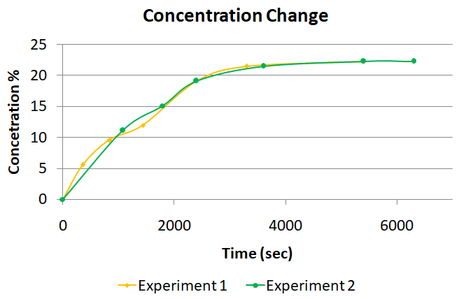
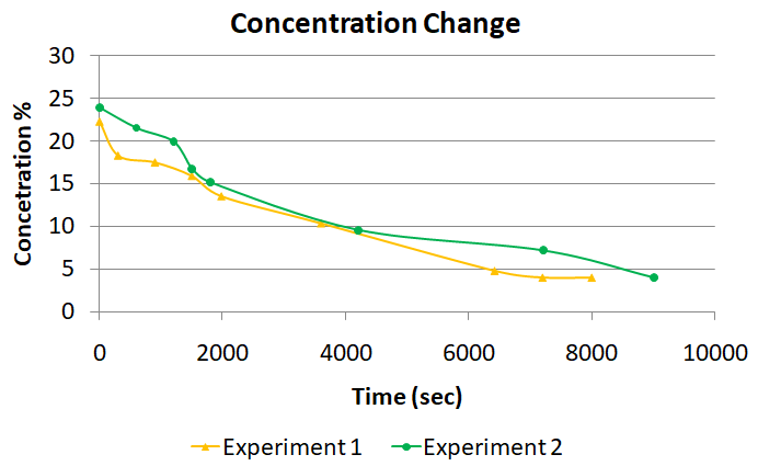
During the adsorption and desorption processes, the water level inside of the evaporator is measured from the sight glass of the evaporator. During reading the water level, the observations are done with measurement error with the range of 1%. The measured amount of adsorbed water with the amount of the dry silica gel gives the average of water concentration in the bed and illustrated in Figure 5. The Figures 5(a) and 5(b) show the concentration change of adsorbent bed during adsorption and desorption, respectively.
 (a)
(a)
 (b)
(b)
 (a)
(a)
 (b)
(b)
4. Conclusion
The heat and mass transfer mechanism of the adsorbent bed controls the performance of the adsorption chiller. Thus, in order to increase the cooling performance of the chiller, an adsorbent bed is designed and constructed. The novelty of the bed is the condenser itself. The condenser is embedded inside of the adsorbent bed. By this design, mainly two advantages can be mentioned;
- The weight of the chiller is reduced due to existence of a component and embedded inside of the bed.
- The cooling performance of the bed is increased due to decreasing the desorption period.
In the present study, the average adsorbent bed temperature, cooling capacity, and the adsorption and desorption rates are measured successfully. For further studies, the size of the particles in the bed can be reduced and the same experiments can be performed.
References
[1] (WoS), Web of science. “Analyze Results of TOPIC: (‘adsorption Chiller’) OR (‘adsorption Refrigeration’) OR (‘adsorption Cool*’) OR (‘solar Chiller’) OR (‘solar Refrigeration’) OR (‘solar Cool*’) OR (‘adsorption Heat Pump’).” 2019.
[2] L. Yong and R. Wang. 2008. “Adsorption Refrigeration: A Survey of Novel Technologies.” Recent Patents on Engineering vol.1 no:1, pp. 1–21. View Article
[3] R.H. Mohammed, O. Mesalhy, M.L. Elsayed, and L.C. Chow. “Performance Enhancement of Adsorption Beds with Silica-Gel Particles Packed in Aluminum Foams.” International Journal of Refrigeration, 2019, vol.104, pp. 201–12. View Article
[4] Z. Chong, Y. Wang, M. Li, and W. Du. “Heat Transfer Performance Investigation on a Finned Tube Adsorbent Bed with a Compound Parabolic Concentrator (CPC) for Solar Adsorption Refrigeration.” Applied Thermal Engineering, 2019, vol.152, pp.391–401. View Article
[5] R.H. Mohammed, O.a Mesalhy, M.L. Elsayed, and L.C. Chow. 2018. “Performance Evaluation of a New Modular Packed Bed for Adsorption Cooling Systems.” Applied Thermal Engineering, 2017, vol.136 pp.293–300. View Article
[6] G.G. Ilis, H. Demir, M. Mobedi, and B.Ba. Saha. “A New Adsorbent Bed Design: Optimization of Geometric Parameters and Metal Additive for the Performance Improvement.” Applied Thermal Engineering 2019. Vol. 162 pp.114270. View Article