Journal of Fluid Flow, Heat and Mass Transfer (JFFHMT)
ISSN: 2368-6111

Volume 8 - Year 2021 - Pages 124-134
DOI: 10.11159/jffhmt.2021.014
Computational Fluid Dynamics-Enabled Modelling and Optimisation of Coolant Flow through Helical Channels
R. Jacklin1, A.S. Johns2, S. Hawley3, E. Merson4, H.M. Thompson1
1School of Mechanical Engineering, University of Leeds, Leeds, LS2 9JT, UK
2Sandvik Limited, Sandviken, Sweden
3Sandvik Coromant, Sheffield, UK
4Lowe & Fletcher Ltd, Wednesbury, UK.
Abstract - Computational Fluid Dynamics (CFD) is used to investigate the effect of geometry and flow parameters on liquid flow in helical channels for conditions relevant to coolant flow in twist drilling applications. CFD predictions of pressure drop in circular and triangular channels are compared against three important experimental correlations and it is shown that the correlation due to Yamamoto et al. [1] is accurate for both circular and triangular channels. Numerical results show how pressure drop varies with pitch, torsion and arc length and how the regions of high velocity flow can be manipulated through helical orientation. A parametrisation of triangular channels is presented and a meta-model for pressure drop created which demonstrates clearly how this depends on corner radius and orientation. Results also show how the larger pressure drop associated with triangular channels, for a given target flow rate, can be reduced towards those for equivalent flows in circular channels by increasing cross-sectional area whilst reducing flow velocities accordingly.
Keywords: CFD, twist-drills, optimisation, helical channels.
© Copyright 2021 Authors - This is an Open Access article published under the Creative Commons Attribution License terms Creative Commons Attribution License terms. Unrestricted use, distribution, and reproduction in any medium are permitted, provided the original work is properly cited.
Date Received: 2020-08-05
Date Accepted: 2020-11-09
Date Published: 2021-02-26
1. Introduction
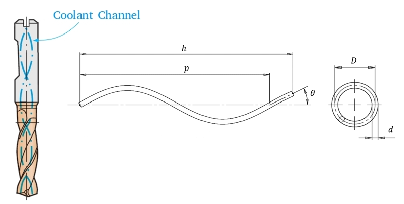
Drilling devices range in size and application from deep-water exploration in the oil and gas industry to micro-drills in medical applications [2]. In a manufacturing context, drilling is a ubiquitous feature of metal forming processes mainly used for assembly purposes such a holes for fasteners and rivets [3]. This paper is motivated by the cooling of fluted twist-drills, which are amongst the most common form of drill used in modern manufacturing, with an estimated market worth around $4 billion per annum [4]. These are commonly used to create cylindrical holes in the manufacture of many important industrial products such as aircraft, cars, ships and trains [5]. Twist-drills typically feature two or more cutting edges and helical grooves around the drill body, where the helix angle varies depending on the application, Figure 1.
Two of the leading causes of failure in twist drills are clogging of the flutes with material removed through cutting (chips) and deformation due to excessive thermo-mechanical loads [6]. Coolant is widely used to improve drill life by transporting heat away from the cutting zone, providing lubrication to reduce frictional losses between the drill and the work-piece and evacuating waste material to prevent clogging [7,8]. Coolant application methods have evolved over the years and flood cooling, by one or more external pressurised jets, remains the most common and mechanically-simple process. However, since coolants typically contain additives such as corrosion inhibitors, biocides and oils, increasing concerns about the environmental and health impacts of flood cooling have stimulated the development of alternative application methods which can lower rates of coolant consumption without compromising performance [7].
A common method of supplying coolant directly to the work-piece-tool interface is through internal helical coolant channels [9], which are usually formed during extrusion of a cylindrical solid rod. Minimum Quantity Lubrication (MQL), which suspends coolant droplets in a stream of compressed air, is an increasingly popular approach, which offers significant reductions in coolant consumption [10]. Recent studies have demonstrated that MQL can reduce significantly both manufacturing costs and environmental impacts while preserving drill life [11], and is a viable alternative to flood cooling [7]. Kao et al. [12] recently used Computational Fluid Dynamics (CFD) to compare the performance of circular and triangular coolant channels in MQL drilling, as a first step towards optimal MQL drill design. Comparisons with their experimental visualisations demonstrated the effect of channel geometry on the mist flow behaviour and the feasibility of using CFD for flow optimisation purposes.
This paper focusses on the application of liquid coolant through helical coolant channels. This is an effective means of delivering coolant directly to the cutting geometry of twist-drills, particularly for deep hole drilling applications, where other techniques fail to provide sufficient coolant [13]. Due to the difficulties in exploring these cooling processes experimentally, a number of studies have used Finite Element Analysis (FEA) and CFD to study the effect of cutting geometry and operating parameters on the effectiveness of using coolant channels to remove heat and chips from the cutting zone. Bono & Ni [14] used FEA to determine the temperature profile along the cutting edge of a drill and showed that the hottest region would be close to the centre of the drill along the chisel edge.
Fallenstein & Aurich [15] used these insights to apply a heat flux boundary condition along the cutting edge of the drill and used CFD to investigate the influence that coolant flow rate and exit position had on drill wear. They validated their CFD approach using high-speed filming on real flow conditions and showed that both flow rate and exit position had a substantial impact on the heat flux between the drill and the coolant. Chowdhury et al. [7] also showed that CFD models can provide an effective means of determining the tool tip temperature during cooling, while Oezkaya et al. [9] used CFD to explore the role of coolant channel flow on the twist-drilling of the super-alloy, Inconel 718. By validating their CFD models against experiments, in which they used a scanning electron microscope (SEM) to measure the width of visible wear on the cutting edge, Oezkaya et al. [9] showed that CFD is a valuable simulation tool for analysing the cooling of twist-drills with internal coolant channels. Their simulations showed that increasing the coolant pressure creates higher flow and heat transfer rates near the cutting edge, which leads to increased drill life. Collectively, these studies demonstrated clearly that the direction of fluid exiting the coolant channels is fundamental to the effectiveness of removing the heat and chips from the cutting zone.
Johns et al. [5] used a finite element-based numerical model of the machining process to determine the shape of the work-piece and chip and loosely coupled this with a finite volume-based two-phase CFD analysis of the distribution of coolant inside the bore-hole to study the effect of channel position on cutting geometry lubrication. Their results showed how the coolant channel position can be used to modify coolant supply to the axial rake, to provide more effective chip evacuation, or to the cutting edge for better heat removal. The numerical model was validated experimentally using a sacrificial polymer coating to indicate coolant delivery regions. Their CFD analysis found several local design optima, but no design which created a fully wetted external drill geometry. They summarised their findings via a meta-model which showed the percentage of the cutting edge covered by the coolant. They used the meta-models to show how locating the coolant channels either closer to or further from the drill axis can promote heat transfer or chip evacuation respectively.
The recent findings by Oezkaya et al. [9] that the pressure of coolant emerging from the helical coolant channels in twist drills has a key impact on the effectiveness of cooling highlights the importance of understanding how flow in coolant channels is influenced by geometrical and operating parameters. Although little research has appeared for the rotating helical flow parameter range specific to twist drilling [2], there is a large literature on flow in non-rotating helical channels due to its importance in a diverse range of applications including heat exchangers, chemical reactors and engine exhaust systems [16]. A number of studies have investigated the secondary flow structures created by the centrifugal forces which drive fluid radially outwards from the axis towards the outer wall where it bifurcates to create two recirculating zones. This phenomenon has been shown to lead to enhanced heat transfer in heat exchangers [17].
Several experimental studies have determined the pressure drop in non-rotating helical channels, resulting in a number of friction factor correlations for different regions of parameter space, see e.g. Ito [18], Srinivasan et al. [19], Yamamoto et al. [1], Guo et al. [20], with Ito’s [18] correlation being perhaps the most widely used formula for turbulent flow in smooth helical channels. Each of these has shown that the helix geometry parameters have a significant influence on the pressure drop in helical channels. CFD has also been used to study flow in non-rotating helical channels. Hüttl & Friedrich [21,22] used CFD to resolve the secondary flow structures in much greater detail than had been presented previously, and demonstrated clearly that helix curvature has a much greater impact on pressure drop than its torsion.
In contrast with the non-rotating case, far fewer studies have considered the effect of the additional coriolis forces caused by rotation, and which arise in twist-drilling. Yamamoto et al. [23,24] found that the secondary flow structures are influenced by both the coriolis and centrifugal forces. When these operate in the same direction, the secondary flow structures are similar to those found in non-rotating cases, however when the forces oppose one another, a more complex secondary flow is formed near the centre of the channel. This work was extended by Zhang and Zhang [25] who used the Dean equations to solve analytically rotating helical pipe flows with circular and elliptical cross-sections, for cases where the coriolis and centrifugal forces are of a similar magnitude. This enabled them to isolate the specific contributions to the secondary flow structure from the curvature, rotation and torsion, with the ratio of the coriolis and centrifugal forces having the key influence on the flow structure.
A number of twist-drill manufacturers have employed non-circular coolant channel geometries for improved coolant delivery, or as a result of their method of rod manufacture. However, the scientific literature on turbulent flow through non-circular helical channels is extremely sparse. Collins and Dennis [26], for example, numerically investigated flow through helical pipes with an isosceles right-angle triangle cross-section. Their simulations showed distinct eddies in the secondary flow at each corner due to enhanced viscous drag near the vertices of the triangle, while Kao et al. [12] compared mist flow for MQL drilling in helical channels of circular or triangular cross-section. The main finding from the latter experimental and numerical investigation was that for circular channels the mist flow is concentrated in the centre, whereas triangular channels draw the fluid into the corners.
This paper aims to expand the scientific literature on turbulent flow in rotating helical channels, by providing greater understanding of the influence of helix geometry and operating parameters on the pressure drop in these flows in regions of parameter space relevant to practical twist-drilling applications. It combines CFD and optimisation techniques to compare coolant flows in rotating helical channels of circular and triangular cross-section and to identify optimal helix parameters which minimise pressure losses in the flow. It is organised as follows. The helix geometry and flow parameters and the flow model are described in section 2. In section 3 model validation and comparison with existing experimental correlations for pressure drop are explored, and a series of results for both circular and triangular helical channels are given, together with meta-models which show the dependence of pressure drop on key parameters. Conclusions are drawn in section 4.
2. Problem Specification
Twist-drills typically feature two or more helical grooves, known as flutes, that are used to transport chips and coolant away from the cutting edge [3], see Figure 1. This paper is concerned with the flow of liquid coolant through the internal helical coolant channels, which supplies coolant directly to the cutting zone.
2. 1. Helical Channel Geometry
The computational grids used in this work are constructed using a transformation approach, which uses the structured grid of a straight pipe and wraps it around the centre-line of a helix. The centreline of the helix is defined by the parametrised curve [27]:

where r (m) is the helix radius, α∈(0,2πn), n is the number of coils of the helix and θ=2πc (m) is the vertical height of one complete helix coil, referred to as the helix pitch. The helix curvature is:

and the torsion, which quantifies the twist along the helix, is:

The channel radius is accounted for by scaling the cross-section of a straight pipe when transforming it into a helix. The arc length along the helix, s (m), is:

The coordinate of the straight pipe identifies the position along the arc length of the straight pipe to the corresponding helical centre point position, R(s), in addition to the T(s), N(s) and B(s), which are the tangent, normal and bi-normal unit vectors at the helix arc length, s. These are defined using the Frenet-Serret formulae:

The transformation is performed by translating points in a straight channel to R(s) then rotating by the N(s) and B(s) unit vectors to correct the inclination of the cross-section. The full transformation of any point along the arc length, s, is given by H(s) where

where Px(s) and Py(s) are the cross-sectional x and y coordinates respectively of any point along the straight pipe at arc length s.
2. 2. Non-Dimensional Parameters
The nature of the flow in helical channels is indicated by the values of three important non-dimensional parameters. The Reynolds number in the channel flow is defined by

where ρ (kg/m3) is the coolant density, U (m/s) is the average fluid velocity, µ (Pas) the dynamic viscosity, and d (m) is the coolant channel diameter. The critical Reynolds number for the onset of turbulence in helical channels has been studied experimentally by Srinivasan et al. [19] and has been summarised as

where D (m) is the helix diameter or distance between the coolant channels. Since this paper focusses on helical flows relevant to twist-drilling applications, taking typical values of d=1mm, D=6.6mm, and 40 m/s ≤ U ≤ 80 m/s [2], yields 40,000 ≤ Re ≤ 80,000, which is significantly larger than Recrit~12,000, so that the flow in coolant channels can be considered to be turbulent. The Dean number is a modified Reynolds number defined by
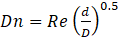
which indicates the significance of centrifugal forces generated by the helical geometry (without rotation). Using the same representative twist drill parameters yields 15,000 ≤ Dn ≤ 30,000 indicating that centrifugal forces will have a significant effect on coolant flow. The Rossby number, Ro, is the ratio of inertial to Coriolis forces, defined by

where Ω is the angular velocity (rad/s), U the average fluid velocity (m/s) and R (m) the radius of the helical channel. For a practical twist-drilling scenario with d=1mm, R=3.3mm and 40m/s ≤ U ≤ 80m/s operating with 1000 rpm ≤ Ω ≤ 10,000 rpm the range is approximately 10 ≤ Ro ≤ 230. Johns [2] found that for such flows, a rotational speed at the upper limit of 10,000rpm only affected the pressure drop compared to the non-rotating case by around 1%. On this basis, the flow modelling is simplified by neglecting the effects of channel rotation.
2. 3. Flow Modelling
Coolants typically contain small amounts of soluble oil and corrosion inhibitors in water [28]. Following the approach adopted in many previous studies [2] the coolant is modelled as a Newtonian and incompressible single-phase liquid and the flow is considered to be isothermal since the heat generation is localised at the cutting zone. The governing Navier-Stokes (NS) equations are solved in the helical channel geometry, namely

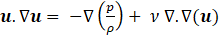
with pressure, p (Pas), density, ρ (kg/m3), kinematic viscosity, ν (m2/s), and a suitable turbulence model is needed to account for the turbulent flow in the helical channel.
The latter has been modelled successfully in a number of studies using the Reynolds Averaged Navier-Stokes (RANS) equations. The k-ɛ model, for example, has been validated successfully against many experimental studies of turbulent flow in helical geometries (see e.g. [12]) while a number of other studies have proposed the use of the SST k-ω model instead [9,15]. These two models are compared in the results presented below.
The boundary conditions for the CFD analyses of flow through the helical coolant channels are as follows. Across the inlet face of the coolant channel, a uniform velocity U in the range 40 m/s ≤ U ≤ 80 m/is specified, while on the outlet face the pressure is set to zero, i.e. atmospheric. At the inlet and outlet boundaries the turbulence intensity, I, is specified in terms of the hydraulic diameter

where A (m2) is the cross-sectional area and pm (m) is the perimeter of the boundary. These are set to those for fully-developed internal flows which can be approximated by I=0.16(RedH) )-0.125 where RedH is the Reynolds number based on the hydraulic diameter dH.
The relevant Navier-Stokes and turbulence modelling equations, subject to the above boundary conditions, are solved using ANSYS Fluent version 19.1.
3. Numerical Results
A series of results is presented for flow in helical channels of circular and triangular cross section. The results for channels of triangular cross section are parametrized in terms of the side length, b, the corner radius, rt,(m) and the angle θt, illustrated in Figure 2.
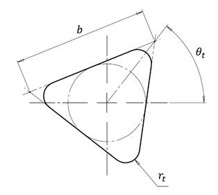
Since the side length b (m) can be specified in terms of the cross-sectional area A and radius rt through the relationship

there are two independent design variables for a specified A.
3.1. Numerical Validation
The effect of grid density on predictions of the pressure drop, Δp (Pas), is first explored for the k-ɛ and SST k-ω turbulence models. Figure 3 shows a typical example of mesh convergence, for an equilateral triangular channel with 20mm pitch, a tool height of 40mm, an inlet velocity 60m/s and rt=0.05mm.
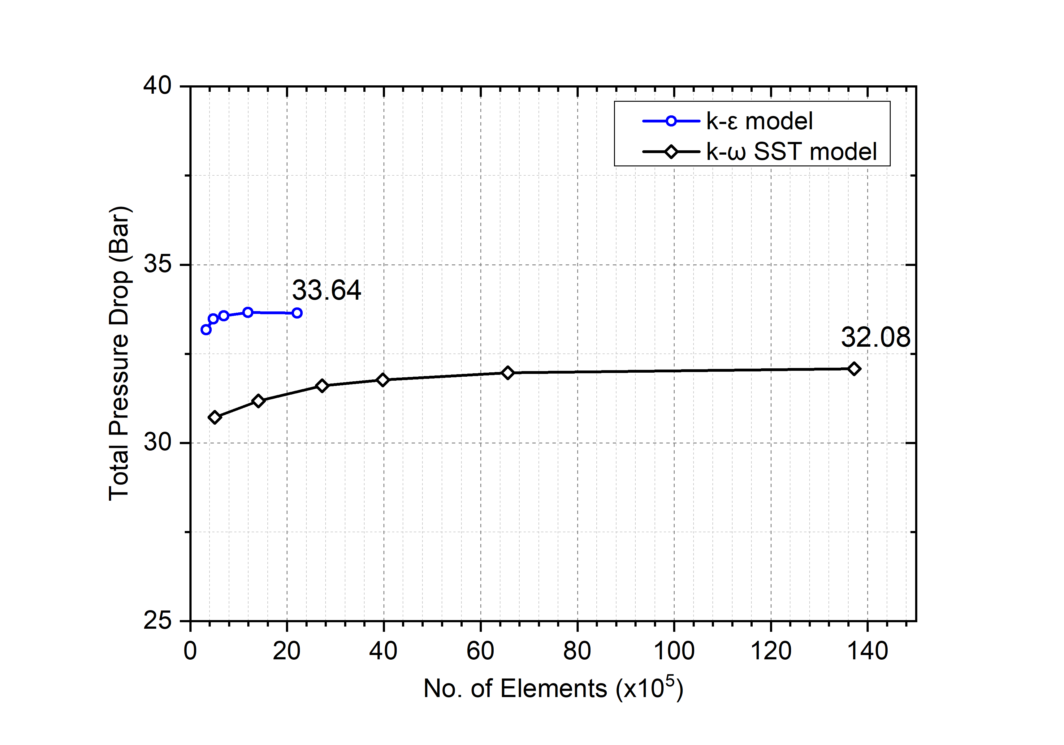
These show that the k-ɛ and SST k-ω models require typically ~4x10⁵ and ~2.5x10⁶ cells to be within 1% of their respective asymptotic Δp values and that the latter are within 5% of each other.
Numerous correlations for Δp in circular, non-rotating, helical channels exist in the literature for a range of different flow conditions. These are usually given in terms of the friction factor, fD, defined by the Darcy-Weisbach equationex geometries such as cambered airfoils, and at larger angles of attack.

where L (m) is the channel length. Here the numerical results are compared for three of the most popular correlations for turbulent flow in smooth helical pipes. The first is that of Yamamoto et al. [1], which modified the earlier experimental correlation of Ito [18] and is referred to here as the IY correlation:
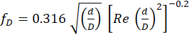
where d (m) is the internal pipe diameter (replaced by dh for non-circular channels) and D is the helix diameter D (twice helix radius r). For all cases in the present study, D=6.6mm. The second correlation is due to Guo et al. [20], which they claimed to be valid for Re ≤ 1.5x10⁵
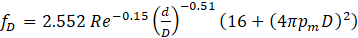
and pm is the channel perimeter. The final correlation considered here is that of Ali [29], developed for helical flow in heat exchangers, which takes the form:

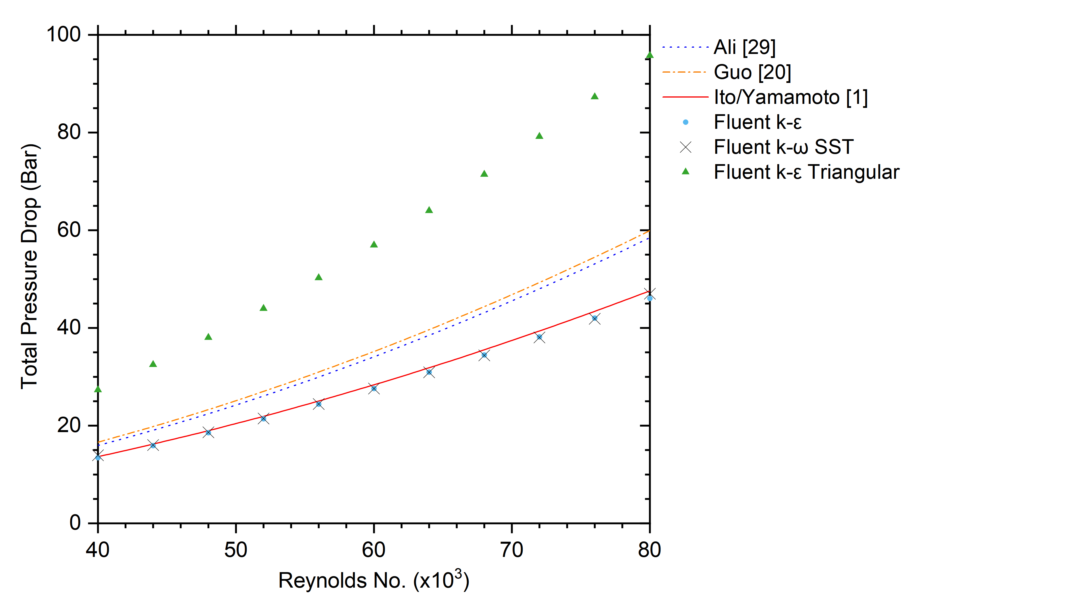
Figure 4 compares CFD predictions of Δp, from the k-ɛ and SST k-ω turbulence models, against these three correlations, for a circular, helical channel with a pitch of 20mm, a tool height of 40mm and a cross-sectional area of 0.785mm2. These show that the predictions from the two turbulence models are once again in good agreement, and also agree well with the IY correlation (16) over the entire Reynolds number range. The corresponding k-ɛ predictions for an equilateral triangular channel with the same cross-sectional area and a sharp corner radius rt=0mm are also shown. These are typically double those for the equivalent circular channel. In light of the good agreement between the predictions of the k-ɛ and SST k-ω turbulence models, and the significantly larger cost of the latter, all CFD results presented below have been obtained with the k-ɛ model and ~4x10⁵ cells.
3.2. Channel Flow Structure
The effect of pitch on the flow field within circular and triangular channels is shown in Figure 5.
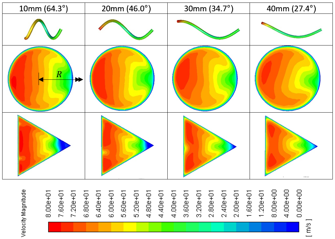
For both channels, the higher velocity fluid is concentrated at the outside channel corners, which is consistent with previous studies by Collins & Dennis [26] and Kao et al. [12]. The results also show how the fluid velocities are more constrained by the triangular shape near the inner channel corner.
Figure 6 shows the effect of channel orientation and corner radius rt on the flow field in triangular channels.
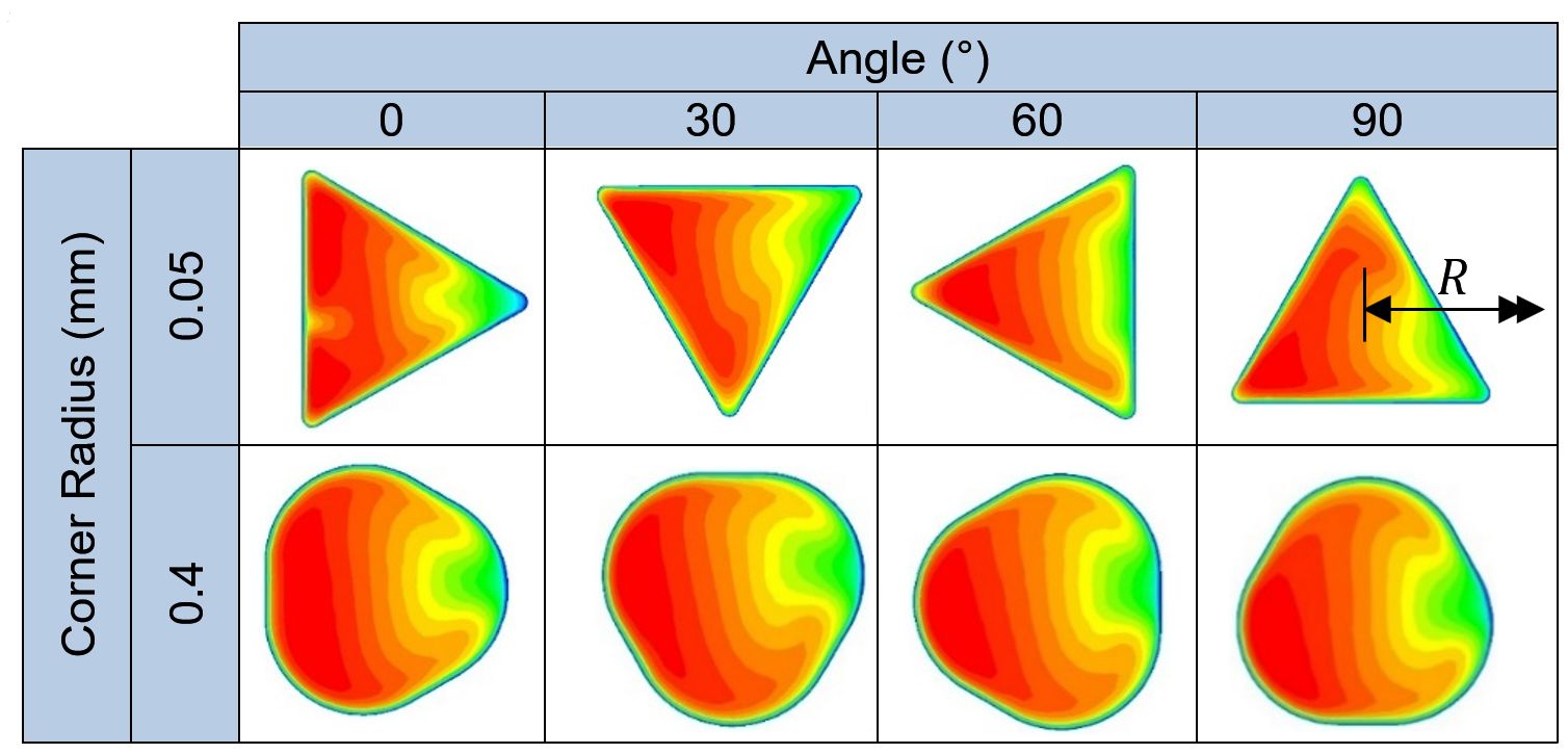
It shows that the orientation can be used to manipulate the regions of high velocity coolant exiting the channel, and that the flows in triangular channels with rt=0.4mm are very similar to those observed in a circular channel. These also support the observations of Oezkaya et al. [9], that channel orientation can provide a useful means of manipulating the regions of high velocity coolant exiting the channel, which can offer significant benefits in terms of cooling critical regions of cutting tools.
3.3. Pressure Drop along Helical Channels
The remaining results focus on the effect of key parameters on pressure drop along helical channels. Figure 7 explores the effect of arc length on pressure drop for circular and triangular channels with a pitch of 20mm and inlet velocity of 60m/s. drop for circular and triangular channels with a pitch of 20mm and inlet velocity of 60m/s.
The triangular channel has an rt of 0.05mm and θt of 66.3° corresponding to the first design point in the meta-model described later. Both cases show a simple, linear dependence with gradients in bar/mm of 0.47 and 0.56 respectively. Once again the pressure drop in triangular channels exceeds that in corresponding circular ones. Additional results, not shown here, demonstrate that the gradient of the triangular channel results increase as rt decreases.
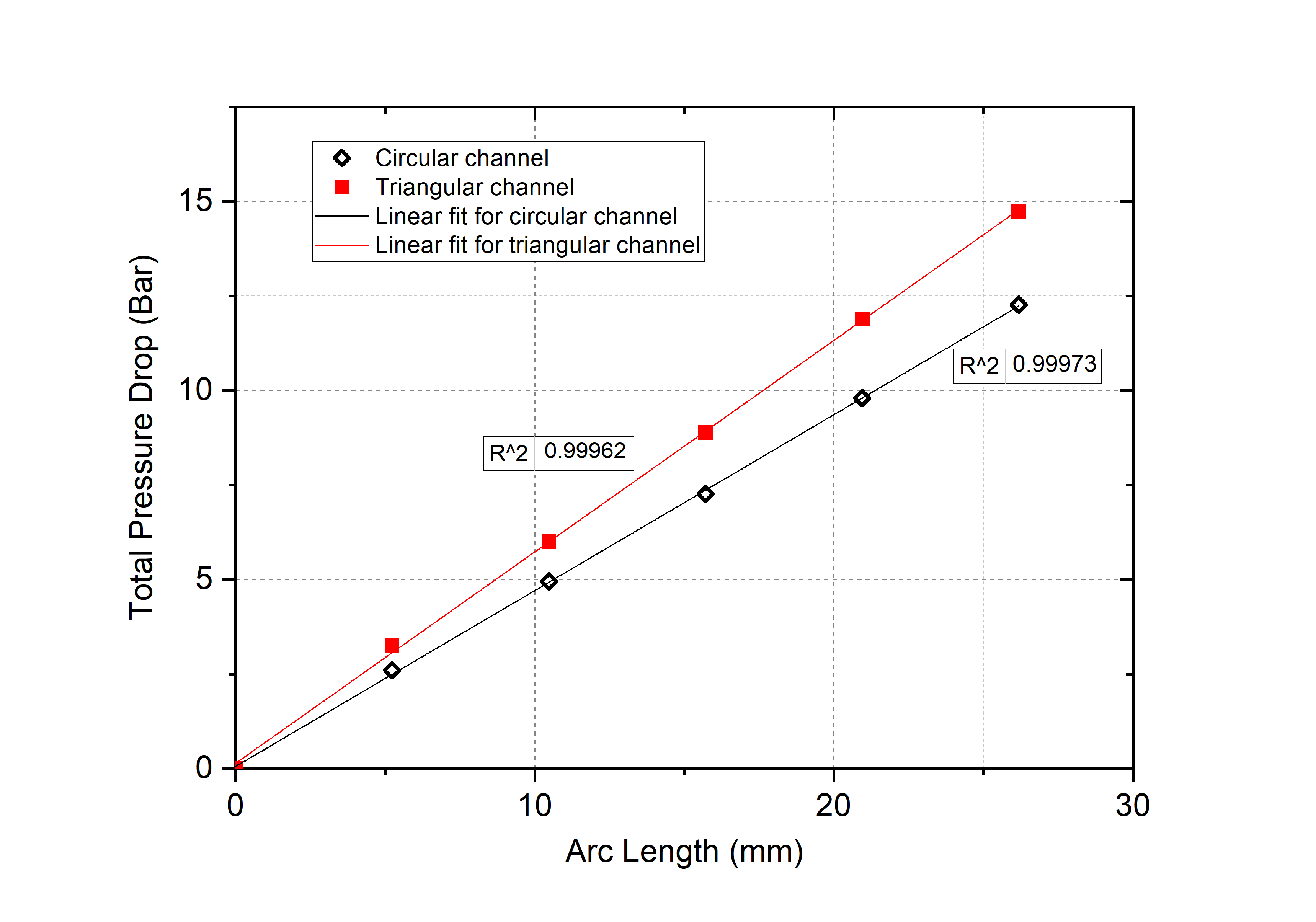
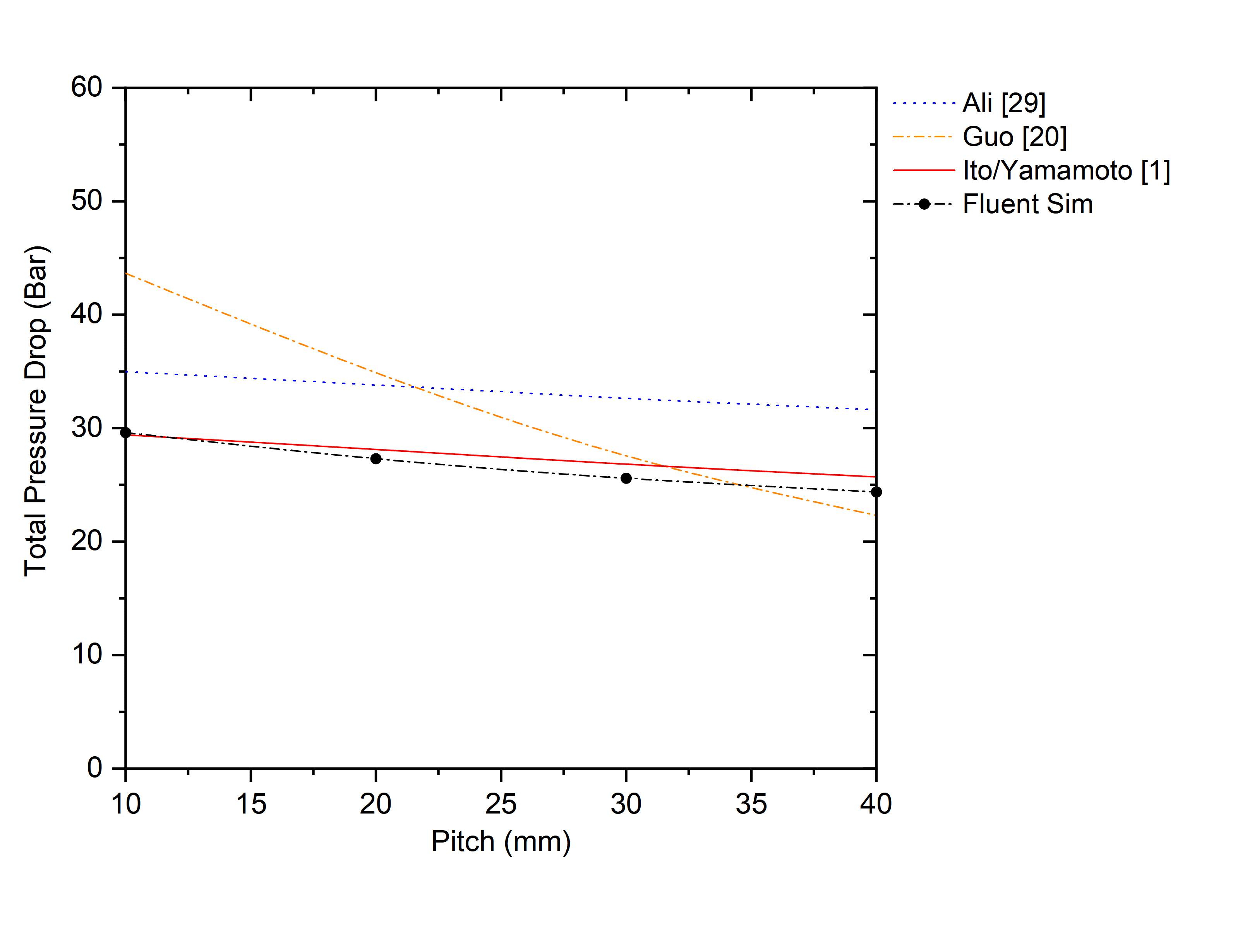
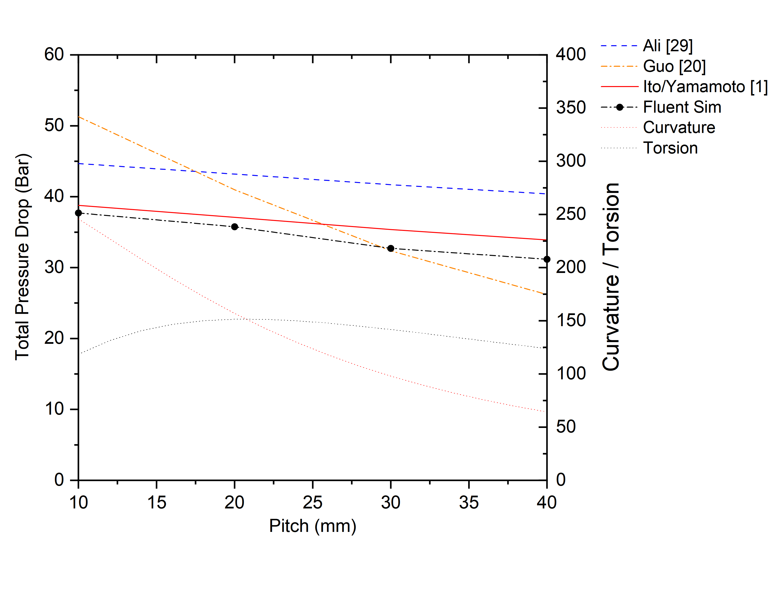
Figure 8 shows the effect of pitch on Δp along a circular coolant channel of a constant arc length. It shows that there is a small, quasi-linear reduction in Δp as pitch increases and that once again the CFD predictions agree generally reasonably well with the IY correlation (16). In contrast the Ali correlation (18) is typically around 15% larger than the CFD predictions while the Guo correlation (17) agrees rather poorly with the CFD for small pitches, but agrees better than the Ali correlation (18) for pitches > 20mm.
The corresponding results for a triangular channel with θt of 0° and sharp corners are shown in Figure 9. Although the pressure drops for the triangular channel are generally larger, similar dependencies on pitch are observed as for the circular channel: small, linear reductions in Δp as pitch increases. Note also that both the general shape and magnitude of the CFD predictions are in good overall agreement with IY correlation (16), where calculations are based on the hydraulic diameter of the triangular channel, over the entire pitch range. The shape of the Ali correlation curve (18) is also similar to that of the CFD predictions, but are typically ~20% larger.
The corresponding results for a triangular channel with θt of 0° and sharp corners are shown in Figure 9. Although the pressure drops for the triangular channel are generally larger, similar dependencies on pitch are observed as for the circular channel: small, linear reductions in Δp as pitch increases. Note also that both the general shape and magnitude of the CFD predictions are in good overall agreement with IY correlation (16), where calculations are based on the hydraulic diameter of the triangular channel, over the entire pitch range. The shape of the Ali correlation curve (18) is also similar to that of the CFD predictions, but are typically ~20% larger. This suggests that the IY correlation (16), developed originally for circular channels, can also be useful for triangular channels when the equivalent hydraulic diameter is used.
We now explore the effect of a triangular channel shape, by considering the influence of rt and θt on Δp for an equivalent 1mm diameter circular channel with A=0.785mm2. A meta-model of Δp throughout the design space with 0.05mm ≤ rt ≤ 0.5mm and 0o ≤ θt ≤ 120o is created using CFD results obtained at 27 points from an Optimal Latin Hypercube Design of Experiments (DoE) [30]. Meta-models in Figure 10, are built using two alternative methods. The first uses inverse multi-quadratic Radial Basis Functions, calibrated using the Leave-One-Out validation approach popular in Machine Learning [31], resulting in an optimal β=0.851. The second uses the Neural Network capability in Matlab with a Levenberg-Marquandt back-propagation training function and a hidden layer size of 10.
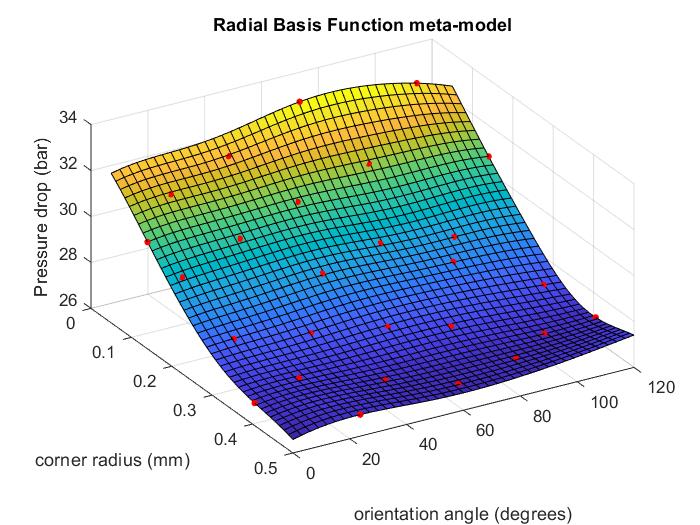
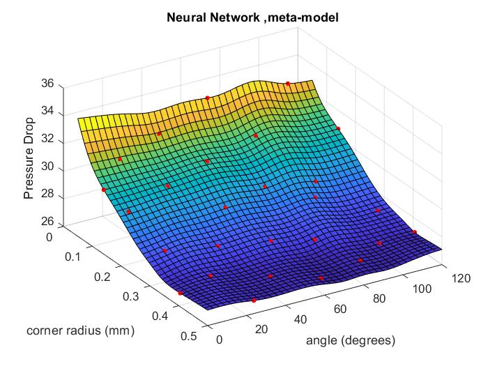
The meta-models are generally similar and show that rt, has by far the dominant effect on Δp, with θt having much less influence. For example for θt =0o, increasing rt from 0.05mm to 0.5mm (a circular channel) leads to an 18% reduction in Δp from 32.5 bar to 26.6 bar respectively. For θt=60o, the corresponding figures are a 20% reduction in Δp from 33.5 bar to 26.8 bar. In contrast, varying θtthroughout 0o ≤ θt ≤ 120o produces only a ~3% variation in Δp for both rt=0.05mm and rt=0.5mm. These findings are consistent with Kao et al. [12] who suggested that smaller radii create thicker boundary layers near the corners leading to higher viscous drag.
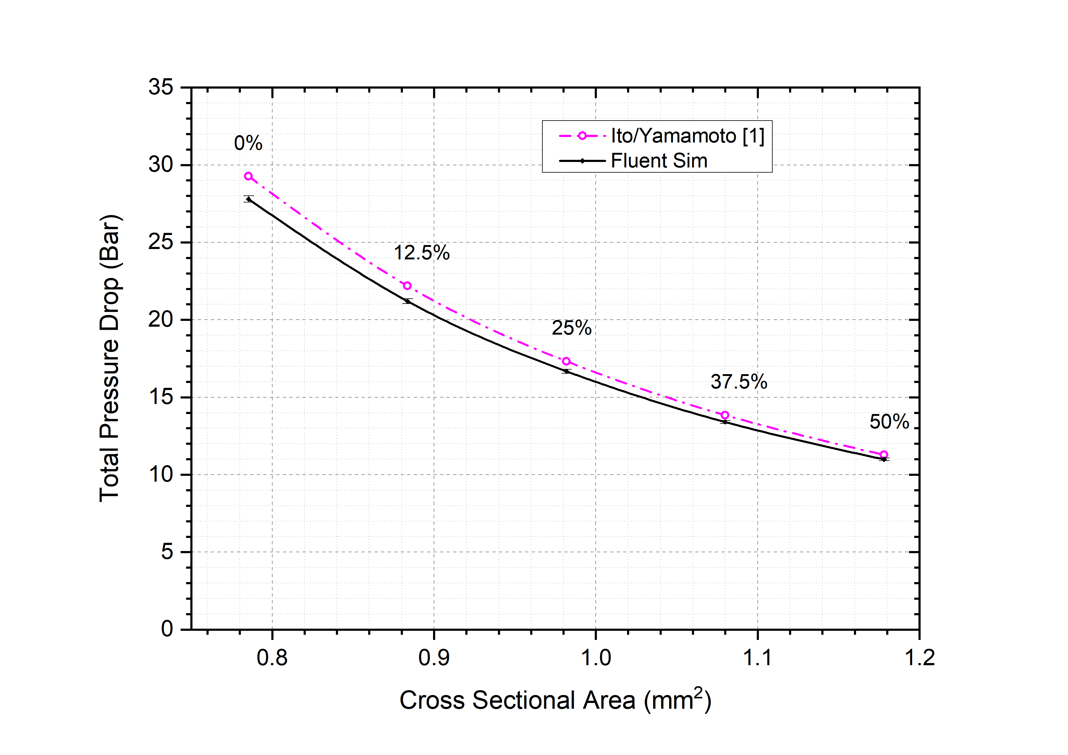
The above results indicate that the use of a triangular helical channel can create as much as a 20% pressure drop penalty compared to a circular one with the same cross-sectional area A. The effect of A on Δp is now explored briefly using a triangular channel with initial rt=0.3mm. To maintain the aspect ratio of the channel profile, the ratio of side length b to rt was kept constant at 4.99 by allowing both rt and b to increase with cross sectional area following equation (14). In all cases, the flow rate was also fixed by ensuring the product U x A remains constant. For these conditions, with A=0.785mm2, Δp=27.3 bar and 35.8 bar for the circular and triangular channels respectively. The effect of increasing A on Δp, for the same flow rate, in a triangular channel is shown in Figure 11 and CFD predictions are compared with the IY correlation for circular channels. The results show that increasing A leads to a substantial reduction in Δp and that these can be predicted accurately, even for triangular channels, by the IY correlation (16) using the hydraulic diameter. For example, an increase in A of 12.5% from A=0.785mm2 to A=0.884mm2 reduces Δp from 27.8 to 21.2 bar, a reduction of approximately 24% compared to the original triangular profile with rt=0.3mm and 22% compared to that for a circular channel with A=0.785mm2.
4. Conclusions
This paper uses CFD to investigate the effect of helix geometry and flow parameters in regions of parameter space relevant to coolant channels in twist drilling applications. In such cases, Coriolis forces due to drill rotation can be neglected [2].
Results for flow through circular and triangular helical channels show that the pressure drop increases linearly with arc length along the helix and that, for the same hydraulic parameter, those in triangular channels are larger than in circular ones, a feature which may become disadvantageous for deep hole drilling applications. A number of experimental correlations for pressure drop in helical channels exist in the literature and results presented here demonstrate that the correlation of Yamamoto et al. [1], which built on the earlier work of Ito [18], agrees well with the CFD predictions for both circular and triangular channels. This correlation therefore provides a simple and convenient means of estimating pressure drop for practical flows in helical channels.
A simple parametrisation of triangular channels is presented and the results demonstrate how angular orientation can be used to manipulate the regions of high velocity flow within channels, with potential practical benefits in terms of directing flow towards critical cooling regions. Meta-models for pressure drop in triangular channels shows more clearly how this depends on the channel orientation and corner radius. Finally, the results show how the increased pressure drop associated with triangular channels can be mitigated, for a given flow rate, by increasing the cross-sectional area and reducing the flow velocity accordingly.
References
[1] Yamamoto, K., Akita, T., Ikeuchi, H., Kita, Y. Experimental study of the flow in a helical circular tube. Fluid Dynamics Research, 16(4), 237-249, 1995. View Article
[2] Johns, A.S. Computational Fluid Dynamic Modelling and Optimisation of Internal Twist-Drill Coolant Channel Flow, PhD thesis, University of Leeds, 2015.
[3] J R.R. Kibbe, R.O. Meyer, J.E. Neely, W.T. White. Machine tool practices. 9th edition, Upper Saddle River, NJ: Pearson Education, 2010.
[4] I. Wright. Global machine tool consumption to rise in 2017. (accessed, 21/12/18).View Article
[5] A. Johns, E. Merson, R. Royer, H. Thompson, J. Summers. A numerical investigation of through-tool coolant wetting behaviour in twist-drilling, Journal of Fluid Flow, Heat and Mass Transfer, 5, 44-52, 2018. View Article
[6] P.F. Zhang, N.J. Churi, Z.J. Pei. C. Treadwell Mechanical drilling processes for titanium alloys: a literature review. Machining Science and Technology: An International Journal, 12(4), 417-444, 2008. View Article
[7] S.A. Chowdhury, M.N. Islam, B. Boswell. Effectiveness of using CFD for comparing tool cooling methods. Proc. World Congress on Engineering, WCE2014, 2078-0966, 2014.
[8] Y. Pei, R. Yiming, W. Gang. The effect of cutting fluids applied in metal cutting process. Proc. IMechE Part B, Journal of Engineering Manufacture, 230(1), 19-37, 2015. View Article
[9] E. Oezkaya, N. Beer, D. Biermann. Experimental studies and CFD simulation of the internal cooling conditions when drilling Inconel 718. International Journal of Machine Tools and Manufacture, 108, 52- 65, 2016. View Article
[10] A. Shokrani, V. Dhokia, S.T. Newman. Environmentally conscious machining of difficult-to- machine materials with regard to cutting fluids. Int. J. Mach. Tools Manuf., 57, 83-101, 2012. View Article
[11] A. Duchosal, S. Werda, R. Serra, R. Leroy, H. Hamdi. Numerical modelling and experimental measurement of MQL impingement over an insert in a milling tool with inner channels. Int. J. Mach. Tools Manuf., 94, 37-47, 2015. View Article
[12] Y-T Kao, M. Hu, B. Takabi, B.L. Tai. Coolant channel and flow characteristics of MQL drill bits: experimental and numerical analyses. Proc. ASME 2017 Int. Manuf. Sci. and Eng. Conference, MSEC2017, MSEC2017-3060, 2017. View Article
[13] K.S. Woon, G.L. Tnay, M Rahman, S. Wan, S.H. Yeo. A computational fluid dynamics (CFD) model for effective coolant application in deep hole gundrilling. Int. J. Mach. Tools. Manuf., 113, 10-18, 2017. View Article
[14] Bono, M, Ni, J. The location of the maximum temperature on the cutting edges of a drill, International Journal of Machine Tools & Manufacture, 46, 901-907, 2006. View Article
[15] F. Fallenstein, J.C. Aurich. CFD based investigation on internal cooling of twist drills. Procedia CIRP, 14, 293-298, 2014. View Article
[16] Naphon, P., Wongwises, S. A review of flow and heat transfer characteristics in curved tubes, Renewable and Sustainable Energy Reviews, 10(5), 463-490, 2006. View Article
[17] Ishigaki, H. Laminar flow in rotating curves pipes. Journal of Fluid Mechanics, 329, 373-388, 1996.View Article
[18] Ito, H. Frictional factors for turbulent flow in curved pipes, Journal of Engineering, 81, 123-134, 1959. View Article
[19] Srinivasan, P., Nandapurkar, S., Holland, F. Pressure drop and heat transfer in coils, Chem. Eng. 218, 113-119, 1968.
[20] Guo, L., Feng, Z., Chen, X. An experimental investigation of the frictional pressure drop of steam-water two-phase flow in helical coils, Int. J. Heat and Mass Transfer, 44 (14), 2601-2610, 2001. View Article
[21] Hüttl, T. Friedrich, R. Influence of curvature and torsion on turbulent flow in helically coiled pipes, Int. J. Heat and Fluid Flow, 21(3), 345-353, 2000. View Article
[22] Hüttl, T. Friedrich, R. Direct numerical simulation of turbulent flows in curved helically-coiled pipes. Computers and Fluids, 30(5), 591-605, 2001. View Article
[23] Yamamoto, K. Alam, M. Yasuhara, J., Aribowo, A. Flow through a rotating helical pipe with circular cross-section, International Journal of Heat and Fluid Flow, 21(2), 213-220, 2000. View Article
[24] Yamamoto, K., Aribowo, A., Hayamizu, Y., Hirose, T., Kawahara, K. Visualisation of flow in a helical pipe. Fluid Dynamics Research, 30(4), 251-267, 2002. View Article
[25] Zhang, J., Zhang, B. Dean equations extended to a rotating helical pipe flow. Journal of Engineering Mechanics, 129(7), 823-829, 2003. View Article
[26] Collins, W.M., Dennis, S.C.R. Viscous eddies near a 90o and a 45o corner in flow through a curved tube of triangular cross-section, Journal of Fluid Mechanics, 76(3), 417-432, 1976. View Article
[27] Weisstein, E.W. Helix, Wolfram Research Inc., (accessed 20/11/18), 2003. View Article
[28] A.D. Jayal et al. Machining performance and health effects of cutting fluid application in drilling of A390. Cast aluminium alloy. Journal of Manufacturing Processes, 9(2), 137-146, 2007. View Article
[29] Ali, S. 2001. Pressure drop correlations for flow through regular helical coil tubes. Fluid Dynamics Research. 28(4), pp.295-310. View Article
[30] Narayanan, A., Toropov, V., Wood, A. Campean, I. Simultaneous model building and validation with uniform designs of experiments, Engineering Optimization, 39(5), 497-512, 2007. View Article
[31] González Niño, C’, Kapur, N., King, M-P, de Boer, G., Blacker, J., Bourne, R. and Thompson, H. ‘Computational Fluid Dynamic Enabled Design Optimisation of Miniaturised Continuous Oscillatory Baffled Reactors in Chemical Processing’ International Journal of Computational Fluid Dynamics, 33 (6-7), 317-332, 2019. View Article